

S&P EC-3N, EC-5N, EC-9N, EC-12N, EC-15N User Instructions
EC-3N
EC-5N
EC-9N
EC-12N
EC-15N
Instrucciones de uso
User Instructions
Notice d’utilisation
Istruzioni sull’uso
Användar instruktion
Instruçoes de utilizaçao
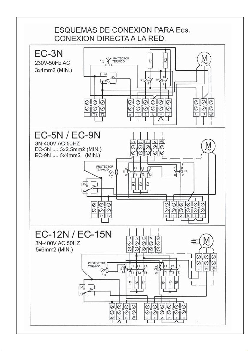
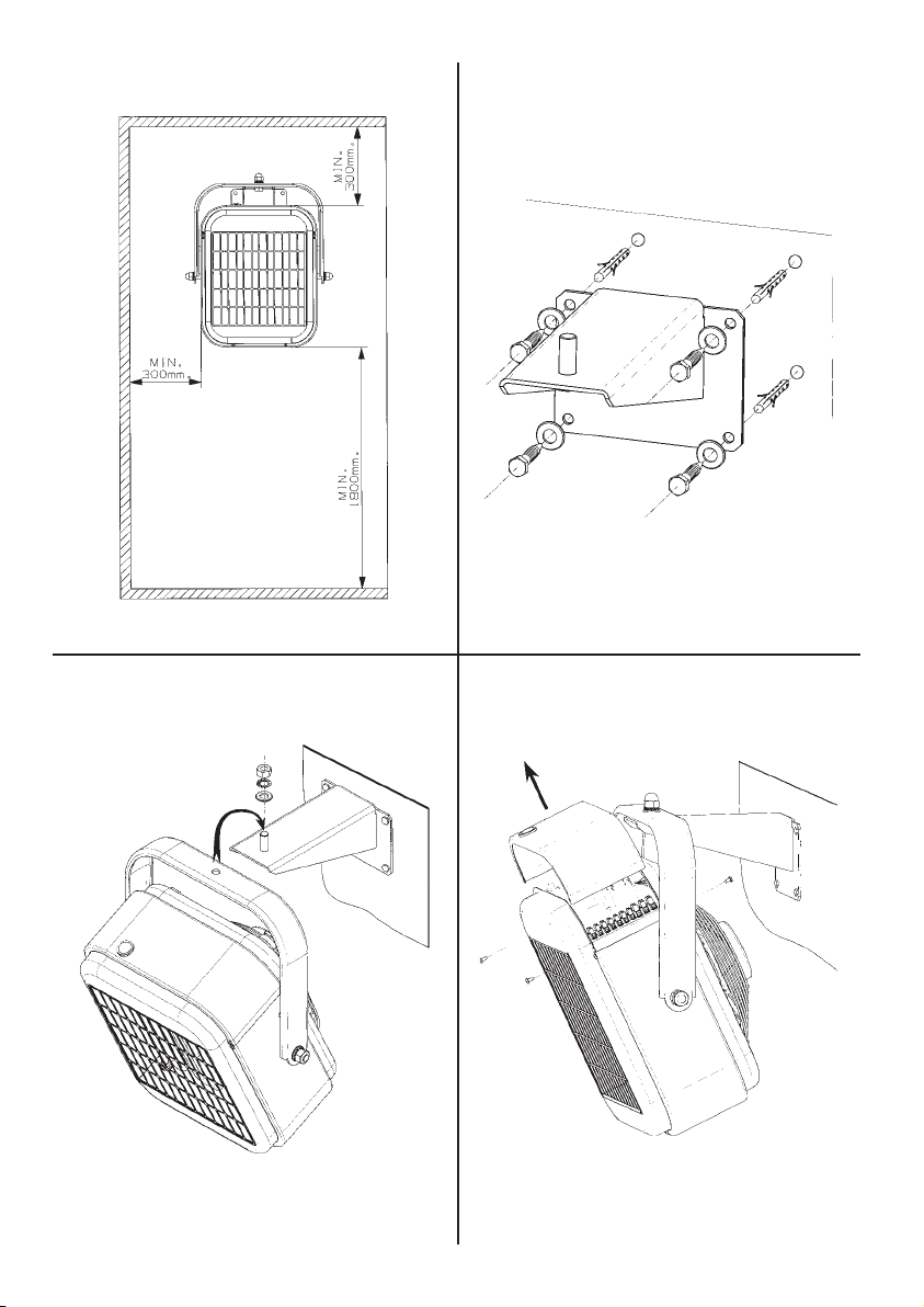
Fig.1 Fig.2
Fig.3 Fig.4
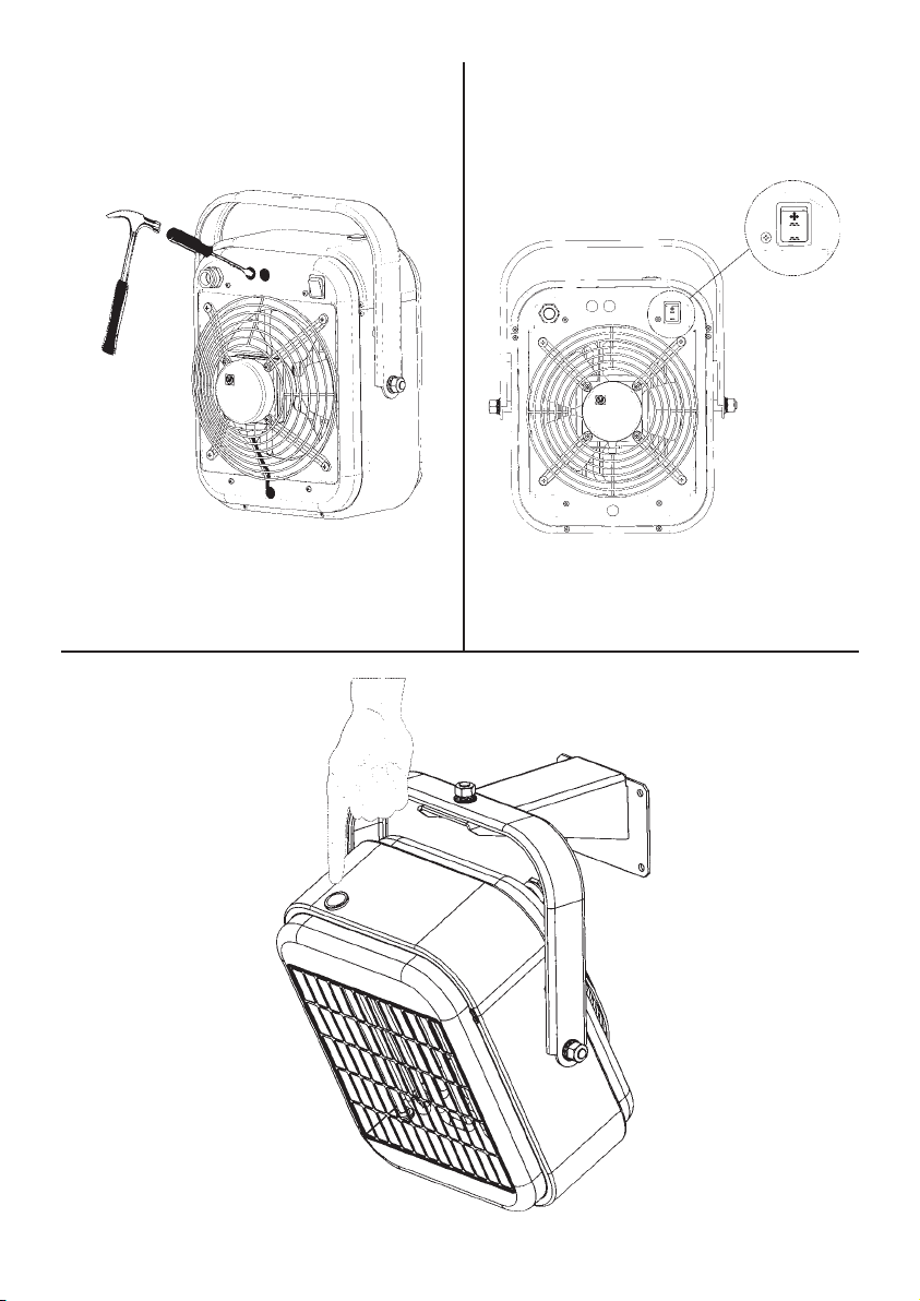
Fig.5 Fig.6
Fig.7

ESPAÑOL
AEROTERMOS COLGABLES.
Lea atentamente estas instrucciones antes de utilizar el aparato.
Los Aerotermos de la gama EC cumplen
las normas europeas de seguridad.
Se recomienda comprobar el estado y funcionamiento del aparato al desembalarlo,
cualquier defecto de origen está amparado por la garantía.
RECOMENDACIONES DE SEGURIDAD.
-La instalación debe ser realizada por un
técnico electricista.
-La instalación deberá realizarse de acuerdo con las reglas nacionales de instalaciones eléctricas.
-No sitúe el cable delante de la salida del
aire ni en contacto con las paredes del
Aerotermo mientras esté en funcionamiento.
-No coloque objetos inflamables a menos
de 50 cm del chorro de aire caliente.
-No instale el Aerotermo debajo o encima
de una base de toma de corriente.
-No cubra el Aerotermo con objetos que
impidan la libre circulación del aire. Si se
cubre, existe el riesgo de
sobrecalentamiento.
-Mantenga limpias las rejillas de entrada
y salida de aire.
-No toque el aparato con las manos húmedas.
-Si se instala en un cuarto de baño, deberá colocarse de manera que los interruptores u otros dispositivos de mando no
puedan ser tocados por una persona que
esté en la bañera o ducha.
LAR EN LOCALES CON AMBIENTE
HÚMEDO.
-COMPRUEBE QUE LA TENSIÓN DE LA
RED COINCIDA CON LA INDICADA EN LA
PLACA DE CARACTERÍSTICAS.
-LA RED ELÉCTRICA DEBERÁ TENER
TOMA DE TIERRA. NO USE
ADAPTADORES NI BASES MÚLTIPLES.
-LOS MEDIOS DE DESCONEXIÓN QUE
DEBEN SER INCORPORADOS A LA INSTALACIÓN FIJA, PARA SU DESCONEXIÓN
OMNIPOLAR DE LA RED DE ALIMENTACIÓN, DEBEN PRESENTAR UNA SEPARACIÓN DE CONTACTOS DE AL MENOS 3
mm EN TODOS LOS POLOS.
IMPORTANTE
Se tiene que prever un espacio suficiente
alrededor del aparato para que haya una
buena circulación de aire. (fig.1)
La distancia mínima entre el Aerotermo y
el suelo debe ser de 1’8m.
INSTALACIÓN
Deberán respetarse las cotas mínimas indicadas en la figura 1.
La unidad deberá ser fijada a una superficie conveniente para tal aplicación.
Para instalar seguir la secuencia siguiente:
1-Utilizando el soporte como plantilla,
marcar los agujeros en la pared, colocar
los tacos apropiados a cada tipo de pared
y atornillar. (fig.2).
2-Colgar el aparato en el soporte(fig.3).
CONEXIONADO ELÉCTRICO
NORMAS DE SEGURIDAD PARA LA INSTALACIÓN
-LOS AEROTERMOS ESTAN
HOMOLOGADOS PARA PODERSE INSTA-
Son aparatos de instalación fija. En su
conexionado a la red, deberán tenerse en
cuenta las directrices que se indican en el
Reglamento de Baja Tensión y las propias
de cada país.
Debe preveerse en la instalación un interruptor magnetotérmico u otro dispositivo de desconexión omnipolar que interrumpa todas las líneas de alimentación
al aparato.
En primer lugar debe desmontarse la tapa
superior(fig.4). El esquema de conexiones
se encuentra debajo de la misma.
Proceder al conexionado a la red, comprobando que la tensión de la misma coincida con la indicada en la placa de características.
Utilizar la sección y número de conductores indicados en los esquemas correspondientes a cada modelo.
La conexión a la red deberá realizarse con
un cable manguera utilizando como entrada de cable el prensaestopas incorporado en el aparato.
CONEXIONADO DEL CONMUTADOR (CR-
25)
Estos aparatos deben ser accionados mediante un conmutador(CR-25) suministrado aparte.
Para su conexión deberá utilizarse uno de
los agujeros previamente troquelados, situados en la parte posterior del aparato y
colocar el prensaestopas adecuado al cable manguera correspondiente. (fig.5)
Para su conexión eléctrica vea el esquema del conmutador CR-25
CONEXIONADO DE UN TERMOSTATO DE
AMBIENTE (TR-1 o TR-2 SEGÚN MODELO)
La temperatura ambiente puede ser regulada mediante un termostato conexionado al aparato.
Para su conexión deberá procederse igual
que el conmutador.
Para la conexión eléctrica vea los esquemas de los termostatos(TR-1 o TR-2).
El termostato TR-1 puede incorporarse a
los modelos EC-3N, EC-5N y EC-9N.
El termostato de dos etapas de temperatura, TR-2 puede incorporarse a los modelos EC-12N y EC-15N. Este termostato
permite una mejora en el diferencial de
temperatura así como un ahorro de energía.
FUNCIONAMIENTO
El conmutador CR-25, funcionará según
la secuencia indicada a continuación.
Las posiciones del conmutador en un sentido u otro son las siguientes:
0 Paro
Ventilación
Semi-potencia de calefacción
Plena potencia de calefacción
-Cuando el conmutador situado en la parte posterior (fig.6), esté en la posición
.......el termostato opcional (TR-1 o TR-2)
actúa únicamente sobre las resistencias,
desconectándolas cuando la temperatura
seleccionada por el termostato esté alcanzada. El ventilador funciona permanentemente.
-Cuando dicho conmutador esté en la posición el termostato actúa a la vez
sobre las resistencias y el ventilador,
desconectándolos cuando se alcance la
temperatura seleccionada con el termostato.
-El termostato fija y mantiene la temperatura deseada.
-Para su actuación gire el mando del termostato hasta su posición máxima.
-Seleccione la potencia.
-Una vez que el local haya alcanzado la
temperatura deseada, gire lentamente el
mando del termostato en el sentido contrario a las agujas del reloj, hasta que con
un suave “clic” se desconecte el aparato.

A partir de este momento el Aerotermo se
conectará y desconectará
automáticamente manteniendo constante
la temperatura preseleccionada, según la
modalidad elegida.
-Desconexión: Sitúe el conmutador en la
posición de paro 0.
NOTA: Las superficies del aparato están
calientes durante el funcionamiento.
DISPOSITIVO DE SEGURIDAD CONTRA
LOS SOBRECALENTAMIENTOS
Los Aerotermos incorporan una protección térmica de rearme manual que desconecta automáticamente los aparatos en
caso de sobrecalentamiento. Si esto ocurriera, debe dejarse enfriar el aparato durante 15 minutos, comprobar que no haya
acumulación de suciedad en las rejillas y,
si fuera preciso, limpiarlas después de
desconectar el aparato de la red.
Vuelva a poner en marcha el Aerotermo
apretando el pulsador RESET situado encima del aparato (fig.7).
Si el problema persiste, le rogamos que
acuda a la Red de Servicios Oficiales S&P.
MANTENIMIENTO
-Desconecte el aparato de la red antes de
efectuar cualquier operación de mantenimiento, utilizando el interruptor
magnetotérmico u otro dispositivo de corte omnipolar.
-Cada temporada limpie el polvo acumulado en el interior haciendo pasar un chorro de aire a presión a través de las rejillas
de entrada y salida. Dicha limpieza es conveniente que sea efectuada por un
-Limpie regularmente las rejillas de entrada y salida de aire.
-No sumerja el aparato ni lo ponga debajo
del grifo.
técnico.
-No desmonte ni manipule el aparato, ello
anularía automáticamente la garantía.
-Si la instalación está protegida por un
interruptor diferencial de alta sensibilidad
y se desconecta al poner en marcha el aparato, puede ser debido a la presencia de
humedad en el interior de las resistencias
de calentamiento. Estas resistencias pueden acumular humedad en su interior si
no se utilizan durante un periodo de tiempo prolongado. Esto no puede ser considerado como un defecto. Para remediar
esta situación, conecte el aparato en una
toma de corriente sin interruptor diferencial. La duración del secado puede durar
horas o incluso días. Una buena prevención sería conectar periódicamente el aparato.
NOTA: Es muy importante, que como mínimo, una vez al año se efectúe una limpieza a fondo del aparato, disminuyendo
de esta forma el riesgo de accidentes.
Norma: Estos aparatos cumplen con el
reglamento sobre perturbaciones
radioeléctricas e interferencias contando,
de ser preciso, con los elementos
antiparasitarios necesarios.
ASISTENCIA TÉCNICA
La extensa red de Servicios Oficiales S&P
garantiza una adecuada asistencia técnica en cualquier punto de España.
En el caso de observar alguna anomalía
en el aparato, rogamos se ponga en contacto con cualquiera de los servicios mencionados, donde será debidamente atendido.
Cualquier manipulación efectuada por personas ajenas a los Servicios Oficiales S&P
nos obligaría a cancelar su garantía.
S&P se reserva el derecho a modificaciones del producto sin previo aviso.

ENGLISH
HANGING (CEILING MOUNTED)
AEROHEATERS
Carefully read the following instructions
before using the apparatus.
The EC N range of Aeroheaters comply with
the European safety regulations
It is recommended that on receiving the
apparatus it is checked for defects and
correct operation. Any defects from origin
are covered by the guarantee.
SAFETY RECOMMENDATIONS
- The installation should be carried out
by a qualified electrician
- All installation work should be carried
out in accordance with all applicable
existing national and local regulations
covering electrical installations.
- Do not locate the cable in front of the
air outlet nor in contact with the walls
of the Aeroheater during function.
- Do not place flammable objects within
at least 50cm of the hot air stream.
- Do not cover the Aeroheater with
objects that may restrict the free flow
of air. If the airflow is restricted this
may lead to overheating.
- Ensure that both the air inlet and outlet
grilles are clean and free from
obstructions.
- Do not touch the apparatus with wet
hands.
- If the apparatus is installed in a
bathroom, it should be installed in
such a way that the switches or other
controls are not accessible to anyone
bathing or having a shower.
IMPORTANT SAFETY INFORMATION
ALL S&P AEROHEATERS ARE CERTIFIED
FOR INSTALLATION IN HUMID
ATMOSPHERES.
BEFORE INSTALLATION CHECK THAT THE
MAINS ELECTRICAL VOLTAGE AND
FREQUENCY COINCIDES WITH THE
VOLTAGE SHOWN ON THE PRODUCT
DATA PLATE.
THE MAINS ELECTRICITY SUPPLY
SHOULD BE EARTHED. DO NOT USE
ADAPTERS OR MULTIPLE SOCKETS.
THE APPLIANCE SHOULD BE CONNECTED
TO THE MAINS ELECTRICAL SUPPLY
WITH CORRECTLY SIZED CABLES AND
SHOULD INCLUDE A DOUBLE POLE SWITCH WITH A CONTACT CLEARANCE OF AT
LEAST 3MM.
IMPORTANT
The apparatus should have sufficient space
around it for the circulation of air (fig.1)
The minimum distance between the
Aeroheater and the floor should be a
minimum of 1.8m.
INSTALLATION
The minimum distances in fig.1 should be
observed.
The unit should be fitted to a fixed surface
suitable for this type of installation.
For installation the sequence below should
be followed:
1- Using the support as a guide, mark
the position of the holes in the wall/
ceiling and use the appropriate rawplugs for the type of wall/ceiling. Fix
the support using screws. (fig.2)
2- Hang and fix the apparatus from the
support. (fig.3)
ELECTRICAL CONNECTION
All S&P Aeroheaters are designed for
permanent connection to the electrical
supply. When connecting to the mains
supply, follow the directives for low voltage
installations and the pertinent regulations
for each country.
The installation should be provided with
an isolator or disconnection device that
disconnects all electricity supply to the
apparatus.
First, remove the upper cover (fig.4). The
electrical wiring diagram is stored below
this cover. Proceed with the connection to
the mains supply, having checked that the
mains supply voltage coincides with the
voltage shown on the product data plate.
Use wiring conductors of the same
diameter and number shown on the
diagrams that correspond to each model.
The connection to the mains electrical
supply should be made using protected
cable and should enter the apparatus
through the cable grip provided.
CONNECTION TO THE COMMUTATION
SWITCH (CR-25)
These apparatus should be linked to the
mains through a commutation switch (CR-
25), supplied separately.
To make the connection, use one of the
previously marked holes, situated at the
rear of the apparatus and fit the cable grip
to the corresponding protected cable.
For electrical connections see the CR-25
commutation switch diagram.
CONNECTION TO AN AMBIENT
THERMOSTAT (TR-1 OR TR-2)
The ambient temperature can be regulated
automatically by connecting a thermostat
to the apparatus.
For connection, follow the installation
procedure outlined for the commutation
switch CR-25.
For the electrical connections, see the
thermostat diagrams (TR-1or TR-2)
The TR-1 thermostat can be used with
(fig.5)
models EC-3N, EC-5N and EC-9N.
The TR-2 thermostat can be used with
models EC12N and EC-15N. This
thermostat allows an improvement in
temperature differential and energy
savings.
OPERATION
The CR-25 commutator operates as
described below.
The positions on the commutator are as
follows:
0 Stop
Ventilation
Half power heating
Full power heating
When the commutation switch at the rear
of the apparatus (fig.6) is in the position
.......the optional thermostat (TR-1 or TR-
2) acts only on the heater elements,
disconnecting them when the selected
temperature is reached. The fan functions
permanently.
When the commutator is in position the
thermostat acts on the heater elements and
the fan, both being disconnected when the
selected temperature is reached.
The thermostat fixes and maintains the
desired temperature.
To operate, turn the thermostat control to
the maximum position
Select the power.
Once the surrounding area has reached the
desired temperature, slowly turn back the
thermostat control anti-clockwise until a
slight “click” is heard. The Aeroheater will
now connect and disconnect automatically,
maintaining the pre-selected temperature
constant, according to the mode selected
To disconnect: Situate the commutation
switch in the “0” position.
NOTE: the surfaces of the apparatus are
hot during operation.

OVERHEATING: SAFETY DEVICES
The Aeroheaters incorporate thermal
protection which prevents the apparatus
from overheating by automatically
disconnecting the apparatus. This device
needs to be manually reset. If the device
activates, wait for 15 minutes to allow the
apparatus to cool, check that the grilles are
not dirty and, if necessary, disconnect the
apparatus from the mains supply and clean
them.
To operate the apparatus again, push the
RESET button located at the top of the
apparatus. (fig.7)
If the problem persists, contact S&P
Official Service Network.
MAINTENANCE
-Disconnect the apparatus from the
mains electricity supply, using the
mains switch, before carrying out any
maintenance operations.
- Each season, clean the accumulated
dust from the interior of the apparatus
using a compressed air jet to blow
through the inlet and outlet grilles.
This operation should be carried out
by a qualified technician.
- Regularly clean the air inlet and outlet
grilles
- Do not submerge the apparatus or place it below a tap.
- Do not disassemble or manipulate the
apparatus, as this will invalidate the
guarantee.
time. This is not considered as a defect.
To correct the situation, connect the
apparatus to the mains without the
differential switch. The drying out period
could last hours or even days. A good
means to avoiding this situation is to
operate the apparatus periodically.
NOTE: To ensure safe and trouble free
operation is very important that the
appliance is cleaned at least once a year.
Standards: These apparatus comply with
the regulations governing radio-electrical
interference, and has the required
screening devices.
TECHNICAL ASSISTANCE
The extensive network of S&P Official
Service Agents guarantees technical
assistance in any place in Europe.
In the case that the product does not
operate correctly, please contact any of the
previously mentioned services to resolve
the problem.
Any manipulation of the apparatus made
by personnel other than S&P Official
Services will invalidate the guarantee.
S&P reserve the right to modify the product
without prior notice.
A sensitive internal differential switch
protects the appliance which sometimes
disconnects the apparatus from the supply.
This is normally due to the presence of
humidity in the heater elements. These
elements may accumulate humidity in their
interior when not used for long period of

FRANÇAIS
AEROTHERMES MURAUX FRANÇAIS
Lire attentivement ces instructions avant
d’utiliser cet appareil.
Les aérothermes de la gamme EC N sont
conformes aux normes européennes.
Vérifier l’état et le fonctionnement de
l’appareil dès l’avoir sorti de son emballage.
Tout éventuel défaut d’origine étant couvert
par la garantie.
Recommandations de sécurité:
-L’installation devra être réalisée par un
installateur professionnel qualifié, en
accord avec les règlements nationaux
concernant les installations électriques
- Ne pas faire passer le câble
d’alimentation électrique devant la grille
de sortie d’air chaud, ni le mettre en
contact avec les parois quand
l’aérotherme est en fonctionnement
- Ne pas placer d’objets inflammables à
moins de 50 cm du flux d’air chaud
- Ne pas installer l’aérotherme
directement en dessous d’une prise de
courant
- Ne pas couvrir l’aérotherme avec des
objets pouvant empêcher la libre
circulation de l’air et entraîner une
surchauffe de l’appareil
- Maintenir les grilles d’entrée et de sortie
d’air, propres
- Ne jamais toucher l’appareil avec les
mains mouillées ou humides
Normes de sécurité pour l’installation
- Les aérothermes sont homologués
pour être installés dans les locaux
humides et mouillés (volumes 2 ou 3
d’une salle de bains ou salle d’eau) à
condition qu’ils soient protégés par un
disjoncteur différentiel de 30 mA
maximum.
- Vérifier que l’alimentation électrique
(tension et fréquence) est compatible
avec les valeurs indiquées sur la plaque
caractéristique.
-L’installation doit prévoir une prise de
terre. Il est déconseillé l’utilisation de
rallonge ou d’adaptateur multiprises.
- En cas de raccordement direct au
réseau, la ligne électrique devra prévoir
un système de coupure omnipolaire
ayant une ouverture entre contacts d’au
moins 3 mm, bien dimensionné par
rapport à la charge et conforme aux
normes en vigueurs.
IMPORTANT
- Il doit être prévu un espace suffisant
autour de l’appareil pour qu’il existe une
bonne circulation d’air.
- Si l’installation est fixe, placer
l’aérotherme à une distance minimale
de 1,8 mètres du sol et en respectant
les distances indiquées fig.1. Ne pas
installer les convecteurs sur un mur fabriqué en matériaux combustibles
(bois, plastique, etc..)
Installation
1- Utiliser le support pour marquer
l’emplacement des trous de fixation
sur le mur. Prévoir les vis et chevilles
suffisamment dimensionnées et en
fonction du type de mur (fig.2).
2- Placer l’aérotherme sur le support
(fig.3).
3- Orienter l’aérotherme et serrer toutes
les vis.
Raccordement électrique
L’installation devra être réalisée en accord
avec les règlements nationaux concernant
les installations électriques en basse
tension
Prévoir un système de coupure
omnipolaire du type magnéto-thermique
ou autres en amont de l’aérotherme.
Démonter le couvercle de l’aérotherme
(fig.4). Le schéma de raccordement
électrique est placé au dos de ce couvercle.
Raccorder l’aérotherme au réseau en
utilisant des câbles électriques ayant une
section égale à celle indiquée sur le schéma
Les câbles électriques devront être
introduits dans l’aérotherme par le presseétoupe.
Raccordement du commutateur CR-25
Ces aérothermes doivent être pilotés par
le commutateur CR-25 vendu séparément,
comme accessoire.
Pour le raccorder, défoncer un des trous
pour le passage du câble électrique et placer un presse-étoupe fonction du type de
câble utilisé.
Pour le raccordement suivre le schéma
joint avec le commutateur(fig.5).
Raccordement à un thermostat
d’ambiance (TR-1 ou TR-2 suivant le
modèle)
La température ambiante peut être régulée
par un thermostat pilotant l’aérotherme.
Pour le raccordement suivre le schéma
joint avec le thermostat.
Le modèle TR-1 est un thermostat à 1
étage et est à utiliser avec les
aérothermes EC-3N, EC-5N et EC-9N.
Le modèle TR-2, est un thermostat à 2
étages et est à utiliser avec les modèles
EC-12N et EC-15N.
Fonctionnement
Le commutateur CR-25 permet 4
positions.
0 Arrêt
Ventilation
puissance de chauffage
pleine puissance de chauffage
Fonctionnement avec thermostat
- Quand l’interrupteur situé à l’ar
rière de l’aérotherme (fig.6) sur
la position le thermostat
pilote uniquement les résistances
de chauffage, coupant leur ali
mentation quand la température
sélectionnée par le thermostat est
atteinte. Le ventilateur fonctionne
en permanence
- Quand l’interrupteur situé à l’arrière de
l’aérotherme (fig.6) sur la position le
thermostat pilote les résistances de
chauffage ainsi que le ventilateur,
coupant leur alimentation quand la
température sélectionnée par le
thermostat est atteinte.
-Le thermostat fixe et maintient la
température de confort désirée. Pour
cela :
-Tourner la commande du
thermostat jusqu’à sa position
maximum
- Sélectionner la puissance de
chauffage
- Quand la température, dans le
local à chauffer, aura atteint le
niveau désiré, tourner la commande du thermostat en sens
inverse des aiguilles d’une
montre, jusqu’à ce que s’entende un léger «clic». Laissant
le thermostat sur cette position,
l’aérotherme maintiendra la
température ainsi sélectionnée
en se mettant en marche et en
s’arrêtant automatiquement
suivant la modalité de fonctionnement choisie.
 Loading...