

Page 1
EBB-100 N
Page 2
7
1
5
2
6
3
4
9
8
Fig.1A
Fig.1B
3
7
6
Fig.2B
Fig.2A
Page 3
N
Fig.3
LA LB
EBB- S
N
L
N
L
N
LB
LA
Fig.5A
N
LB
LA
Fig.5B
N
LB
LA
Fig.6A
N
LB
N
REB
L
LA
Fig.6B
Page 4
EBB- T
LS
L
LS
L
N
N
N
L
Fig.7A
EBB- HT
N
L
Fig.8A
MODELOS (T)
2
A
15
T(min.)
Fig.9A
N
L
Fig.7B
LS
L
N
LS
L
N
N
L
Fig.8B
MODELOS (HT)
60
70
LS
N
L
HR(%)
90
T(min.)
80
NLLS
Fig.9B
Page 5

POLSKI
WYCI G OD RODKOWY EBBĄŚ
Wyci gi serii EBB zosta y wyprodukowaneął
zgodnie z rygorystycznymi normami
produkcyjnymi i kontroli jako ci, w cznie z ISOśłą
9001. Ka dy element zosta ażł
wszystkie aparaty podlegaj testom poą
zako czeniu sk adaniańł
Zalecamy sprawdzenie nast puj cych punktówęą
w chwili odbioru niniejszego wyci gu:ą
1- czy model jest prawid owył
2- czy wszystkie dane s okre lone odpowiednioąś
na tabliczce znamionowej: napi cie,ę
cz stotliwo , pr dko ....ęśćęść
ZALECENIA DOTYCZ CEĄ
BEZPIECZE STWAŃ
stalacja winna by przeprowadzona zgodnie zć
-In
przepisami obowi zuj cymi w danym kraju.ąą
Instalacja winna by wykonana przezć
wykwalifikowanego specjalist .ę
Instalacja elektryczna powinna obejmować
wy cznik wielobiegunowy z odst pem mi dzyłą ę ę
stykami przynajmniej 3 mm, dostosowany do
obci enia oraz zgodny z obowi zuj cymiąż ą ą
normami.
Aparat nale y instalowa w azienkach pozażćł
zasi giem osoby bior cej prysznic lub k pi cejęą ąą
si w wannie, a wy cznik winien byęłąć
umieszczony na zewn trz azienki.ął
Nie stosowa tych wentylć
- atowów w powietrzu o
cechach wybuchowych lub korozyjnych.
Je eli urz dzenie EBB ma funkcjonowa wżą ć
kuchni, w której zainstalowany jest piec lub inne
urz dzenie spalinowe, które potrzebujeą
powietrza do prawid owego funkcjonowania,ł
sprawdzi czy wloty powietrza w pomieszczeniuć
s wystarczaj ce.ąą
Nie mo na pod czy wyj cia wyci gu dożłąćś ą
przewodu wykorzystywanego do wyci ganiaą
dymu z aparatów gazowych lub dzia aj cych nałą
inne paliwo.
W przypadku znacznej wilgotno ci doradzamyś
zainstalowanie przewodu wyjsciowego poziomo,
o s abym nachyleniu na zewn trz.łą
INSTALACJA
WA NA UWAGA: Przed przyst pieniem doŻą
instalacji i pod czeniaurz dzenia, pami taj ołą ą ę
od czeniupr du.łą ą
Rysunek 1A:
1- Pokrywa przednia
2- Obudowa wentylatora
3- Zatrzask pokrywy przedniej
4- Rama wspornika
wa po czełą ń
5- Pokry
6- Rowki
zweryfikowany,
.
7- Zatyczki
8- Po czenie ko nierzowe wyj ciowe 80łą ł ś
9- Po czenie ko nierzowe wyj ciowe 100łą ł ś
Wentylatory serii EBB winny by instalowaneć
-
wewn trz pomieszcze poza zasi giemąńę
wp ywów pogodowych, zarówno w pozycjił
pionowej, jak i poziomej.
Wyci g jest przewidziany do pod czenia doąłą
przewodu o rednicy 80 lub 100mm.ś
Przed zainstalowaniem urz dzenia, sprawdziąć
czy turbina obraca si bez oporów.ę
W celu zapewnienia lepszej skuteczno ci si yśł
wyci gania:ą
Nie korzysta z przewodów o rednicy poni ejćśż
80mm.
W przypadku korzystania z przewodu gi tkiego,ę
wyci gn go do maksimum.ąąć
Nie umieszcza kolanek bezpo rednio wćś
wyj ciu wyci gu.śą
Zapewni , aby kolanka mia y mo liwie jakćłż
najwi kszypromie .ęń
Monta na powierzchni (rys.ż
1. Wykona otwór w cianie lub suficie oćś
śąęąrednicy 105mm, upewniaj c si czy urz dzenie
pasuje do zaplanowanego miejsca.
2. Zdj przedni pokryw (1) obudowyąć ą ę
wentylatora (2), ostro nie naciskaj c zaciski (3)żą
przy pomocy ma ego rubokr tu (rys.łś ę
Obudowa wentylatora (2) ustawiona jest na
3.
wsporniku (4)przy pomocy 4 rub i 3 ko nierzach;śł
w celu demonta u wyj 4 ruby z boku iżąćś
otworzy 4 ko nierze (7).ćł
4. Umocowa wspornik (4) przy pomocy 4 rub ićś
odpowiednich dla pod o a podk adek,łż ł
sprawdzaj c czy obwód wspornika zgadza si ząę
otworem wykorzystywanym do atwegoł
wprowadzenia wyj cia wentylatora.ś
5. Otworzy pokryw po cze (5) w obudowieć ę łą ń
wentylatora i przeprowadzi kabel przez otwórć
znajduj cy si z ty u.ąęł
6. Ponowniez o y obudow wentylatora (2) wełżć ę
wsporniku (4), mocuj c ko nierze iął
zabezpieczaj c je 4 rubami.ąś
7. Pod czy do ko cówek, przeprowadzaj cłą ć ń ą
kabel tak, jak wskazano na rys.
8. Przestrzega zapisów schematuć
elektrycznego danej wersji instalowanego
urz dzenia (rys.ą
9. Zamkn pokryw po cze (5) przy pomocyąć ę łą ń
śruby.
10.Z powro
(1), zaciskaj c zaciski od góry i do u orazął
przyciskaj c po bokach, aby pokrywa prawidlowoą
wesz a na swoje miejsce.ł
11.Uruchomi wyci g w celu sprawdzenia czyćą
dzia a prawid owo.łł
tem zmontowa pokryw przednićę ą
2A):
1B).
3.
5-8).
Page 6

Monta z wbudowaniem (rys.ż
1. Zastosowa szablondo oznaczenia i wyci ciaćę
panelu, w którym ma by zainstalowaneć
urz dzenie. Dok adnie przeczyta instrukcjeął ć
umieszczone na szablonie.
2. Post powa jak w krokach 1, 2 i 3 instrukcjięć
monta u na powierzchni.ż
3. Otworzy pokryw po cze (5) w obudowieć ę łą ń
wentylatora i przeprowadzi kabel przez otwórć
znajduj cy si z ty u.ąęł
4. Pod czy przewódłą ć o
po czenia wyjsciowego (8-9).łą
5. Umocowa obudow wentylatora (2) przyćę
pomocy 4 rub i podk adek odpowiednich dlaśł
danej powierzchni.
6. Pod czy do ko cówek, przeprowadzaj cłą ć ń ą
kabel tak, jak wskazano na rys. 3.
7. Przestrzeg
elektrycznego danej wersji instalowanego
urz dzenia (rys. 5-8).ą
8. Zamkn pokryw po cze (5) przy pomocyąć ę łą ń
śruby.
9. Z powrotem zmontowa pokryw przednićę ą
(1), zaciskaj c zaciski od góry i do u orazął
przyciskaj c po bokach, aby pokrywa wesz aął
swoje miejsce.
10.Uruchomi wyci g w celu sprawdzenia czyćą
dzia a prawid owo.łł
POD CZENIE ZASILANIAŁĄ
ELEKTRYCZNEGO ( rys. 5-8 )
Przed rozpocz ciem pracy z wentylatoremę
upewni si czy jest od czony od pr du, nawetćę łą ą
je eli jest wy czony.żłą
Upewni si , czy warto ci napi cia ićę ś ę
czestotliwo ci sieci zasilaj cej s identyczne jakśąą
warto ci wskazane na tabliczce znamionowejś
urzadzenia (maksymalne odchylenie w napi ciuię
cz stotliwo ci:ęś
Urz dzenia EBB s urz dzeniami klasy IIąąą
(podwójna izolacja) i nie wymagają
Przestrzega schematu po cze dla danejćłąń
zainstalowanej wersji.
EBB wersja „S”
Podstawowa wersja z silnikiem o dwóch
pr dko ciach, które mo na regulowaęś ż ć
napi ciem. W przypadku tego modelu,ę
przestrzega nast puj cych schematów:ćęą
Rys. 5A z niezale nym wy cznikiemżłą
Rys. 5B Funkcjonowanie przy jednej pr dko ci zęś
tym samym wy cznikiem jak o wietleniełą ś
Rys. 6A z prze cznikiemłą
Rys. 6B - Funkcjonowanie z regulatorem
napi cia typu REBę
a zapisów schematuć
5%).
Funkcjonowanie przy jednej pr dko cięś
Funkcjonowanie przy 2 pr dko ciachęś
2B):
średnicy
80/100mm
uziemienia.
EBB wersja „T”
Modele wyposa one w prze cznik zw oczny,żłął
który mo na Prze czanie zw oczneżłął
umo liwia kontynuowanie funkcjonowaniaż
urz dzenia przez czas okre lony przy pomocyąś
prze cznika zw ocznego po wy czeniu siłą ł łą ę
wy acznikał
W trakcie funkcjonowania zw ocznegoł
urz dzenie EBB dzia a z ma pr dko ci .ąłłąęśą
UWAGA:
do
zw oczny podczas w czania opó niaj cy ołłąźą
50 sekund, co oznacza, e przez pierwsze 50ż
sekund po w czeniuwyci g nie funkcjonuje.łą ą
Rys. 7B Funkcjonowanie z prze cznikiemłą
zw ocznym tak, aby uruchamia si jednocze niełłęś
z w czeniem o wietlenia.łą ś
W celu ustawienia tego prze czania zw ocznegołą ł
(rys. 9A), obróci potencjometr umieszczony podć
pokryw po cze (5).ąłą ń
Urz dzenie mo e by ustawione na 4 pozycjeążć
opó nienia:ź
PozycjaAuto:
Je eli czas wykorzystania nie przekracza 50ż
-
na
sekund, prze czanie zw ocznie nie dzia a.łą ł ł
ssekund, urz dzenie automatycznie kontrolujeą
ustawienie prze cznika zw ocznełą ł
proporcjonalny do czasu wykorzystania przy
maksymalnie 30 minutach.
Pozycja 2':
minut
Pozycja 15':
minut
Pozycja 30': 0
minut
EBB wersja „HT”
Modele wyposa one w elektroniczny hisrostatż
regulowany w zakresie 60-90% WW (wilgotność
wzgl dna w %) oraz prze cznik zw oczny, któryęłął
mo na ustawi w interwa ach 1-30 minut.żć ł
W trakcie funkcjonowania zw ocznegoł
urz dzenie EBB dzia a z ma pr dko ci .ąłłąęśą
Zalecenia:
- W celu zmiany ustawie fabrycznych nale yńż
ustawi potencjometry znajduj ce si obokćąę
pokrywy po cze (rys. 9B). Potencjometry te słą ń ą
łłąęż ćęatwo t uk ce si i nale y obchodzi si z nimi
ostro nie.ż
prawid owa, nale y zainstalowa urz dzenie włż ćą
miejscu, w którym jest dobry przep yw powietrza.ł
pomieszczeniem, w którym zainstalowane jest
urz dzenie.ą
ustawiać
(rys. 7A).
Urz dzenie posiada prze cznikąłą
Je eli czas wykorzystania przekracza 50ż
Prze czanie zw oczne stae co 2łą ł ł
Prze czanie zw oczne sta e co 15łą ł ł
Prze czanie zw oczne sta e co 3łą ł ł
W celu okre laia, czy wilgotno jestśść
Nie zmieni ustawie wilgotno ci pozaćń ś
.
go. Jest on
Page 7

Ustawienia:
Wyci gi s wst pnie ustawione w pozycji 60%ąą ę
WW oraz 1 minuty w zakresie prze czaniałą
zw ocznego.ł
-
Je eli poziom wilgotno ci w pomieszczeniu jestżś
mniejszy ni 60% WW,wyci g nie uruchomi si .żą ę
-
Je eli poziom wilgotno ci przekracza 60% WW,żś
wyciag w czy si automatycznie.łą ę
Je eli poziom wilgotno ci stale przekracza 90%żś
WW, wyci gnigdy si nie wy czy.ąęłą
Je eli chce si zmieni ustawienia, tzn.żęć
utrzyma poziom wilgotno ci w pomieszczeniućś
ponad 60% WW, obróci potencjometr «ć
kierunku ruchu wskazówek zegara.
Je eli chce si zwi kszy czas zw oki, tzn.żęęćł
zwi kszy czas funkcjonowania urz dzenia poęć ą
osi gni ciu wilgotno ci poni ej poziomuąę ś ż
okre lonego ustawieniem w pomieszczeniu,ś
obróci potencjometr «ć
wskazówek zegara.
UWAGA: Nie nale y probowa ustawiażćć
parametrow wyci gu, gdy znajduje si w fazieąę
opó nienia. Nale y odczeka a sko czy siźżćżńę
faza opó nienia przed przej ciem doźś
kolejnego ustawienia.
Funkcjonowanie
Przypadek 1:
automatycznego (rys. 8A) urzadzenie w cza siłą ę
automatycznie z szybk pr dko ci , gdy poziomąę śą
wilgotno ci w pomieszczeniu przekracza poziomś
ustawiony. Wy cza si , gdy poziom wilgotno ciłą ę ś
powróci do warto ci poni ej poziomuśż
ustawionego po up ywie czasu ustawionego wł
prze czniku zw ocznym. Gdy urz dzeniełą ł ą
znajduje si w fazie dzia ania zw ocznego,ęłł
pracuje z pr dko ci woln .ęśą ą
Przypadek 2:
w czaniem/wy czaniem si razem złą łą ę
prze cznikiem o wietlenia (rys. 8B).łą ś
Funkcjonowanie automatyczne podobne do
przypadku 1, leczy urz dzenie w cza si nawetąłąę
wtedy, gdy poziom wilgotno ci w pomieszczenieś
jest ni szy ni poziom ustawiony. W takimżż
przypadku, gdy prze cznik wy cza si (wy czałą łą ę łą
si wiat o), urz dzenie nadal funkcjonuje zęś ł ą
pr dko ci woln przez okres oznaczonyęśą ą
prze cznikiem zw ocznym.łą ł
UWAGA: Gdy poziom wilgotno ci wzgl dnejśę
w pomieszczeniu przekracza ustawioną
warto , funkcjonowanie automatyczne maść
pierwsze stwo nad funkcjonowaniemń
r cznym, tzn. nie mo na wy czy urz dzeniaężłąćą
wy cznikiem.łą
t min.
W przypadku funkcjonowania
Funkcjonowanie automatyczne z
%Hr
» w kierunku ruchu
KONSERWACJA
WA NA UWAGA: Przed przyst pieniem doŻą
konserwacji upewni sie, czy urz dzenie jestćą
od czoneod zasilania elektrycznego.łą
Zalecamy regularne czyszczenie z zabrudze ,ń
jakie mog si gromadzi na 4 filtrach w przedniejąę ć
pokrywce (1).
przedni pokryw jak wskazano w cz ci pt.ąę ęś
„Instalacja” i r cznie umy j ciep wod zęćąłąą
myd em. Sprawdzi czy pokrywa przednia jestłć
ca kowicie sucha przed ponownym jejł
»w
zamontowaniem.
Wyczy ci pozosta e cz ci szmatk nas czonść ł ęś ą ą ą
delikatnym detergentem.
POMOC TECHNICZNA
W przypadku zauwa enia jakiejkolwiek anomaliiż
w funkcjonowaniu urz dzenia, skontaktowa siąćę
z oficjalnie upowa nionym serwisem lub zeż
sprzedawc produktu.ą
Jakiekolwiek zmiany wprowadzone w urz dzeniuą
przez osoby nie upowa nione przez S&Pż
powoduj utrat gwarancji.ąę
(S&P zastrzega sobie prawo wprowadzania
modyfikacji bez uprzedniego powiadamiania.)
W tym celu nale yzdj rzeczonżąć ą
Page 8

ENGLISH
EBB CENTRIFUGAL EXTRACTOR
EBB series extractors have been manufactured
according to strict production and quality control
standards such as ISO 9001. All the components
have been verified and all the devices have been
tested following assembly.
We recommend you to check the following points
when you receive this extractor:
1- Make sure you have received the right model
2- Make sure that the data on the nameplate are
appropriate to your needs: voltage, frequency,
speed, etc.
SAFETY RECOMMENDATIONS
The installation must be carried out in
accordance with current regulations in each
country.
- The installation must be carried out by a
qualified professional.
- The electrical installation must incorporate an
omnipolar switch with an opening between
contacts of at least 3 mm, appropriate for the load
and complying with current standards.
- In bathrooms, the device must be installed
outside the reach of any person taking a shower
or a bath and the switch must be installed outside
the bathroom.
- Do not use these fans in explosive or corrosive
atmospheres. If the EBB is working in a kitchen
where there is a boiler or any other kind of
combustion device that needs air to work, check
that the air inlets to the kitchen are sufficient.
- The extractor discharge cannot be connected to
a conduit for the evacuation of smoke from
devices worked by gas or any other fuel.
- In the event of considerable humidity, you are
advised to install the discharge conduit
horizontally, with a slight outwards slant.
INSTALLATION
IMPORTANT: Before proceeding with the
installation and connection of the device,
make sure to disconnect the electricity
supply.
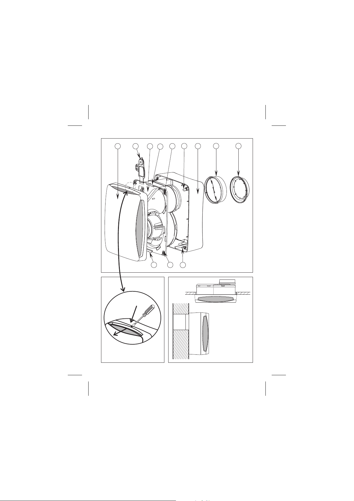
Figure 1A:
1- Front cover
2- Fan body
3- Front cover clip
4- Base frame
5- Connections cover
6- Slots
7- Retainers
8- Discharge flange 80 mm
9- Discharge flange 100 mm
-
EBB series fans must be installed in an area that
is sheltered from meteorological conditions; they
can be assembled either in vertical or horizontal
position.
-
The extractor is designed to be connected to a
80 or 100-mm diameter duct.
- Before assembling the device, check that the
turbine rotates freely.
For your extractor to work more efficiently:
- Do not use conduits whose diameter is less than
80 mm.
- If a flexible conduit is used, stretch it out fully
- Do not place elbows right at the extractor
discharge.
- Elbows should have as large a radius as
possible.
SurfaceAssembly (fig. 2A):
1. Make a 105-mm diameter hole in the wall or
ceiling, making sure that the device fits in the area
you have planned for it.
2. Removethe front cover (1) of the fan body (2)
pressing the clips (3) carefully with a small
screwdriver (fig.1B).
3. Thefan body (2) is secured to the base frame
(4) by means of 4 screws and 4 clips.
To dismantle it, ove the 4 screws from the
corners and open the 4 clips (7).
4. Using4 screws and plugs that are appropriate
for the kind of wall, fix the base frame (4) on to the
surface, ensuring that the circular profile of the
frame coincides with the opening made, so that
the discharge nozzle can be introduced easily
subsequently.
5. Open the connections cover (5) of the fan
body and pass the cable through the hole
provided for this purpose on the bottom of the
terminal box.
6. Reassemble the fan body (2) on to the base
frame (4) by introducing it into the flanges and
securing it with the 4 screws.
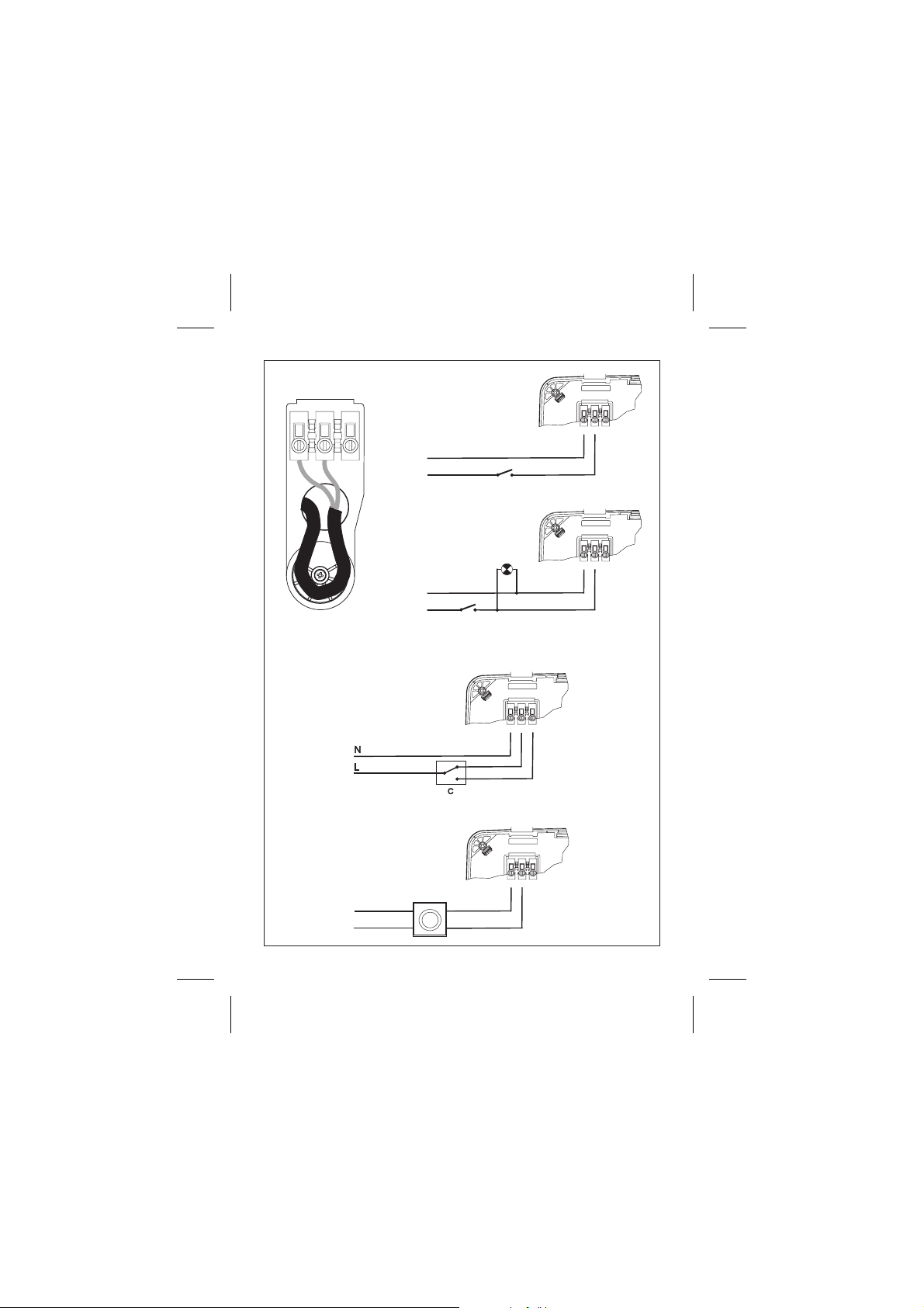
7. Connect to the terminals passing the cable
through as indicated in figure. 3.
8. Follow the electrical diagram applying to the
EBB version that is being installed (fig. 5 to 8).
9. Close the connections cover (5) with the
screw.
10.Assemble the front cover (1) again, pressing
the upper and lower clips and pressing each
corner down to ensure that it fits properly in place.
11.Turn the extractor on to check that it works
properly.
Built-in assembly (fig. 2B):
1. Use the template to mark and cut the panel
into which the device will be installed. Read the
instructions given on the template carefully.
2. Follow steps 1, 2 and 3 of the Surface
Assembly Instructions.
3. Open the connections cover (5) and pass the
cable through the hole provided for this purpose
on the bottom of the terminal box.
4. Connect the duot to the discharge flange (8-9).
5. Secure the fan body (2) using 4 screws and
plugs that are appropriate for the kind of surface.
6. Connect to the terminals, passing the cable
through as indicated in figure 3.
Page 9

7. Follow the electrical diagram applying to the
EEB version that is being installed (fig. 5 to 8)
8. Close the connections cover (5) with the
screw.
9. Assemble the front cover (1) again by
tightening the upper and lower clips and pressing
each corner to ensure that it fits properly in place.
10.Switch the extractor on to check that it is
working properly.
ELECTRICAL CONNECTION (fig. 5 to 8)
- Before working on the fan, make sure that it is
fully disconnected from the electricity supply,
even if it is switched off.
- Make sure that the voltage and frequency
values of the electricity supply are the same as
those indicated on the name plate of the device
(maximum voltage and frequency variation: 5%).
- EBBs are class II (double insulation) devices
and do not require earth connection.
- Follow the connections diagram applying to the
version installed.
EBB version “S”
Basic version with two-speed motor, which can
also be voltage regulated. For this model proceed
according to one of the following diagrams:
Fig. 5A- Single-speed operation with an
independent switch.
Fig. 5B- F Single-speed operation using the same
switch as the light.
Fig. 6A- 2-speed operation with a switch.
Fig. 6B- Operation with an REB-type voltage
regulator.
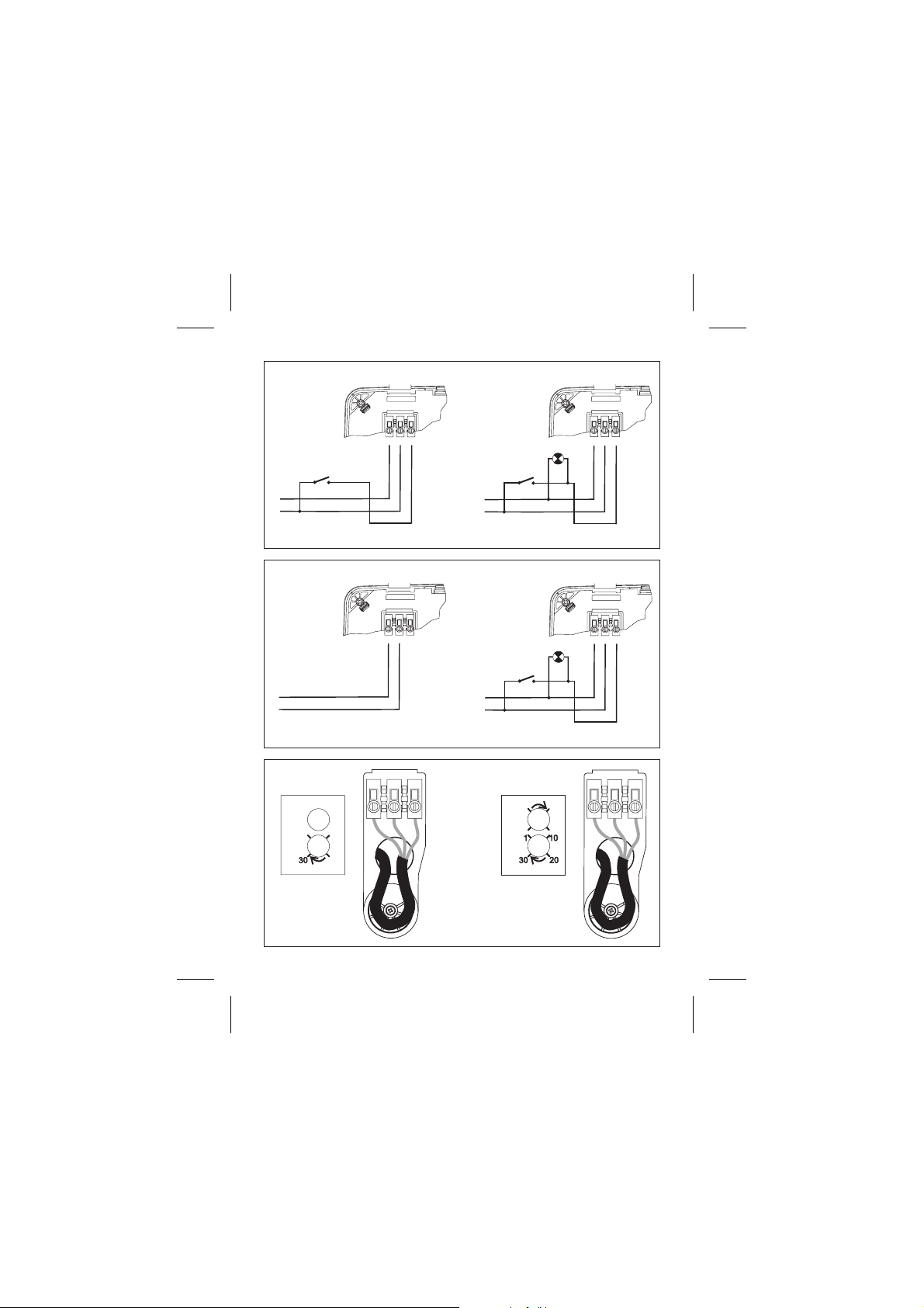
EBB version “T”
Models equipped with timing. The
timing enables the device to operate for the time
set, when the switch has been turned off (fig. 7A).
In timer mode, the EBB operates at slow speed.
ATTENTION
seconds after being switched on, which
means that for the first 50 seconds it does not
work.
Fig. 7B Timer-based operation so that the device
starts up by means of the same switch as the
light.
To set this timer function (fig. 9A), turn the
potentiometer situated beside the connections
cover (5).
The device can be set to 4 different timer
Auto Position
- If the device is used for less than 50 seconds,
the timing will not come into operation.
- If the device is used for more than 50 seconds
the timing is controlled automatically by the
device. It is proportional to the time of use with a
maximum of 30 minutes.
Position 2'
Position 15'
Position 30'
: The device is timed to start up 50
:
: Timingset to 2 minutes
: Timing set to 15 minutes
: Timing set to 30 minutes
adjustable
positions:
EBB version “HT”
Models equipped with an electronic humidistat
that can be regulated between 60 and the 90%
RH (Relative Humidity %) and with timing that can
be set between 1 and 30 minutes.
When in the timer mode the EBB works at slow
speed.
Recommendations
-
In order to modify the factory settings, the
potentiometers situated beside the connections
cover (fig. 9B) will have to be operated. These
potentiometers are fragile and must be handled
with care.
- For correct humidity detection, the device must
be installed in an area in which there is good air
circulation.
- Do not change the humidity setting outside the
area in which the device is installed.
Settings:
The extractors are preset to 60% RH for humidity
and 1 minute for timing.
- If the humidity level in the area is below 60% RH,
the extractor will not start up.
- If the humidity level in the area is above 60% RH,
the extractor will start up automatically.
- If the humidity level is always above 90% RH the
extractor will operate constantly.
- If you wish to modify the settings; that is,
maintain a humidity level of over 60% RH in the
area, turn the “ ” potentiometer clockwise.
- If you wish to increase the timer setting; that is,
increase the time during which the extractor
operates once the humidity level is under the set
level, turn the potentiometer “ “ clockwise.
ATTENTION: You should not attempt to adjust
the extractor settings when the extractor is in
timer mode. You must wait until the set time
has elapsed before adjusting the settings.
Operation
Case 1
: In automatic working mode (fig. 8A) the
device switches on automatically at fast speed
when the humidity level in the area is above the
selected value. It stops when the humidity level
drops below this value and when the time set by
the timer has elapsed. When the device is in timer
mode, it works at slow speed.
Case 2
: Automatic operation with possibility of
turning on the device by means of the light switch
(fig. 8B). Automatic operation similar to case 1 but
with the device will start up even if the humidity
level in the area is below the set value. In this
case, when the switch is turned off (the light is
switched off), the device continues to operate at
slow speed for the length of time set by the timer.
:
%Hr
T min.
Page 10

ATTENTION: When the relative humidity level
in the area is above the set value, automatic
operation prevails over manual operation;
that is, the device cannot be turned off by
means of the switch.
MAINTENANCE
IMPORTANT: Before carrying out any
maintenance operations, make sure to
disconnect the electricity supply.
You are advised to remove any dirt that has
accumulated in the 4 filters of the front cover (1) at
regular intervals. To do so, remove the front
cover as indicated in the “INSTALLATION”
section and hand wash with warm soapy water.
Make sure that the front cover is absolutely dry
before putting it back in place.
Clean the other parts with a cloth soaked in mild
detergent.
TECHNICALASSISTANCE
Should you observe any anomaly in the operation
of the device, contact an official authorised
service or the seller of the product.
If the device is handled by persons who are not
authorised by S&P, the guarantee will be
cancelled.
(S&P reserves the right to make changes
without prior notice.)
 Loading...