

Page 1

SY-D6IGA
Motherboard
***************************************************
Single or Dual Xeon™ processor supported
(Pentium® II Xeon™ & Pentium® III Xeon™)
82440 GX AGP/PCI Motherboard
100MHz Front Side Bus supported
Custom ATX Form Factor
LAN Chip onboard (10/100 Mbps)
Ultra2 SCSI onboard
***************************************************
User's Guide
&
Technical Reference
Page 2

SOYO™ SY-D6IGA
ii
About This Guide
This User's Guide is for assisting system manufacturers and end users in setting up
and installing the motherboard. Information in this guide has been carefully checked
for reliability; however, no guarantee is given as to the correctness of the contents.
The information in this document is subject to change without notice.
Copyright Notice
Copyright 1999, Soyo Computer Inc. All rights reserved. This manual is copyrighted
by Soyo Computer Inc. You may not reproduce, transmit, transcribe, store in a
retrieval system, or translate into any language, in any form or by any means,
electronic, mechanical, magnetic, optical, chemical, manual or otherwise, any part of
this publication without express written permission of Soyo Computer Inc.
Trademarks
Soyo is a registered trademark of Soyo Computer Inc. All trademarks are the property
of their owners.
Disclaimer
Soyo Computer Inc. makes no representations or warranties regarding the contents
of this manual. We reserve the right to revise the manual or make changes in the
specifications of the product described within it at any time without notice and without
obligation to notify any person of such revision or change. The information contained
in this manual is provided for general use by our customers. Our customers should be
aware that the personal computer field is the subject of many patents. Our customers
should ensure that their use of our products does not infringe upon any patents. It is
the policy of Soyo Computer Inc. to respect the valid patent rights of third parties and
not to infringe upon or assist others to infringe upon such rights.
Restricted Rights Legend
Use, duplication, or disclosure by the Government is subject to restrictions set forth in
subparagraph (c)(1)(ii) of the Rights in Technical Data and Computer Software clause
at 252.277-7013.
Product Rights
Products mentioned in this manual are mentioned for identification purpose only.
Product names appearing in this manual may or may not be registered trademarks or
copyrights of their respective companies.
If you need any further information, please come to our home page on the Internet.
The address is "http://www.soyo.com.tw".
Edition: April 1999
Version 1.0
D6IGA SERIAL
FC
C
Tested To Comply
With FCC Standards
FOR HOME OR OFFICE USE
POST CONSUMER
RECYCLED PAPER
100%
Page 3

Table of Contents SY-D6IGA
iii
Table of Contents
THE SY-D6IGA MOTHERBOARD.................................................1
SY-D6IGA MOTHERBOARD LAYOUT..........................................2
CHAPTER 1 INTRODUCTION ......................................................3
1-1 KEY FEATURES.......................................................3
1-2 HANDLING THE MOTHERBOARD...........................6
1-3 ELECTROSTATIC DISCHARGE PRECAUTIONS.....6
CHAPTER 2 HARDWARE SETUP................................................7
2-1 PREPARATIONS......................................................7
2-2 UNPACKING THE MOTHERBOARD........................8
2-3 INSTALLATION GUIDE.............................................9
CHAPTER 3 BIOS SETUP UTILITY............................................33
3-1 SOYO COMBO SETUP..........................................35
3-2 STANDARD CMOS SETUP....................................40
3-3 BIOS FEATURES SETUP.......................................43
3-4 CHIPSET FEATURES SETUP................................48
3-5 POWER MANAGEMENT SETUP ...........................51
3-6 PNP/PCI CONFIGURATION SETUP.......................55
3-7 LOAD SETUP DEFAULTS......................................58
3-8 INTEGRATED PERIPHERALS ...............................59
3-9 SUPERVISOR PASSWORD...................................64
3-10 USER PASSWORD ................................................65
3-11 IDE HDD AUTO DETECTION.................................66
CHAPTER 4 DRIVERS INSTALLATION......................................67
Page 4

Table of Contents SY-D6IGA
iv
CHAPTER 5 PRO/100+™ LAN ADAPTER INSTALLATION.........73
5-1 PRO/100+™ - MICROSOFT
INSTALLATION NOTES..........................................73
5-2 PRO/100+™ - ALL NETWARE PRODUCTS
INSTALLATION NOTES..........................................88
5-3 PRO/100+™ - UNIX INSTALLATION NOTES.........107
CHAPTER 6 ULTRA2 SCSI I/O SUBSYSTEM ..........................112
6-1 INTRODUCTION TO ULTRA2 SCSI .....................112
6-2 INSTALLING SCSI DEVICES................................113
6-3 CONNECTING INTERNAL SCSI DEVICES..........114
Page 5
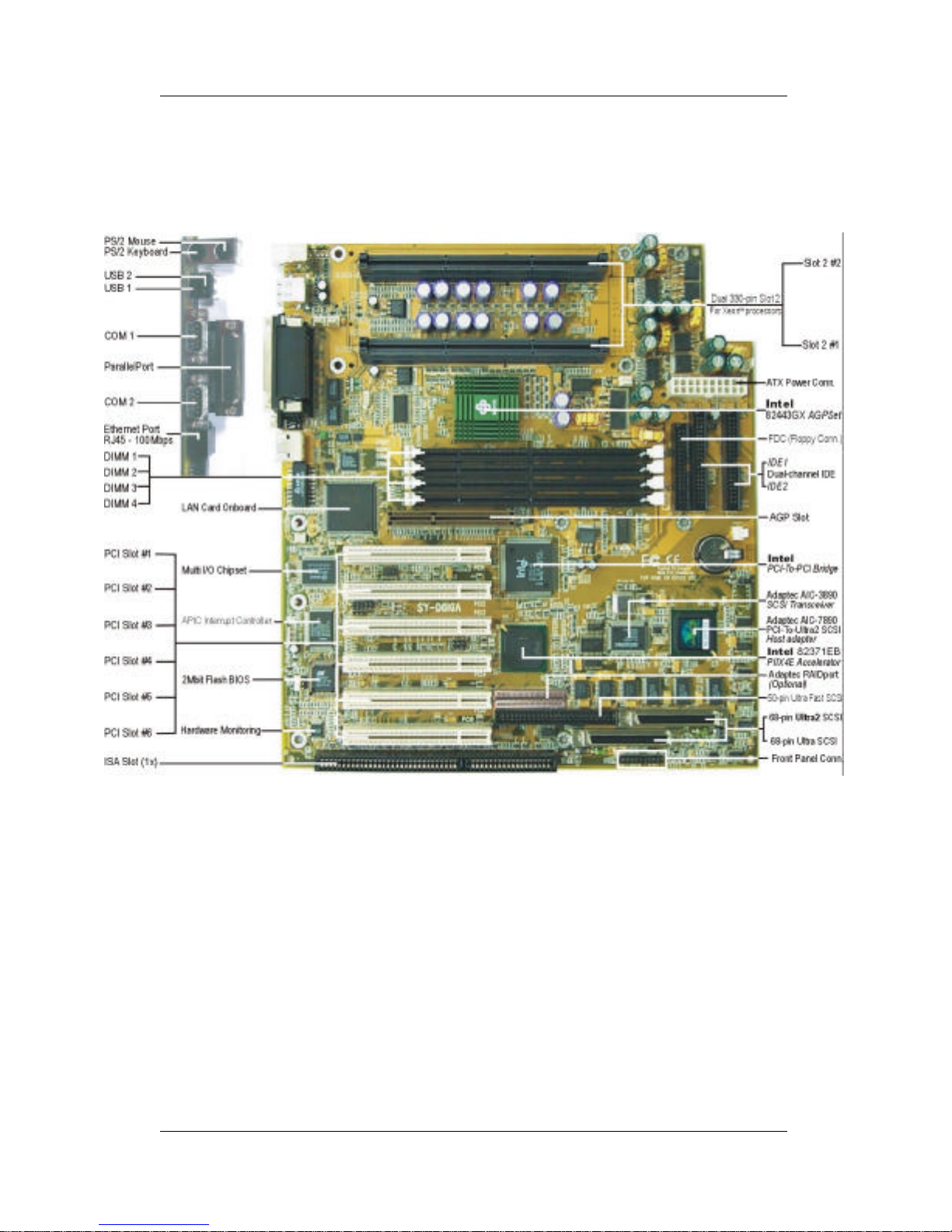
The SY-D6IGA Motherboard SY-D6IGA
1
THE SY-D6IGA MOTHERBOARD
Page 6
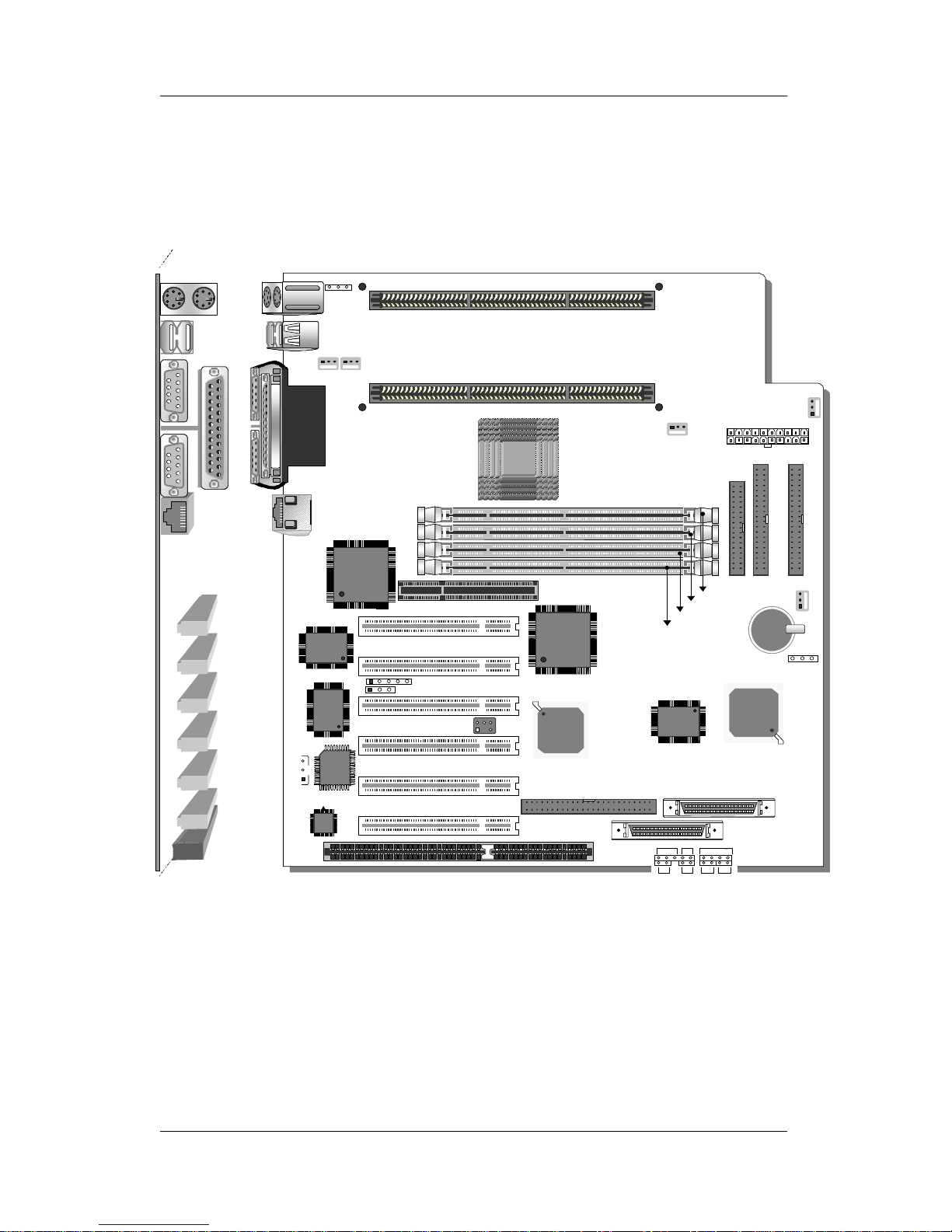
Motherboard Layout SY-D6IGA
2
SY-D6IGA MOTHERBOARD LAYOUT
Back Panel SY-D6IGA Platform
COM 1
COM 2
USB 1
PRT
USB 2
PS/2 KB
Connector
PS/2 Mouse
Connector
Ethernet
RJ-45
Intel
®
82371 EB
AGP Slot
1
FDC
IDE 2
1
DIMM 1
DIMM 2
DIMM 3
DIMM 4
SB-LINK™
(PC-PCI)
Wide SCSI (68-pin)
Narrow SCSI (50-pin)
1
1
1
IDE 1
PCI Slot #1
PCI Slot #2
PCI Slot #3
PCI Slot #4
W83781D
828AC
Hardware Monitoring
3V
Lithium
Battery
PCI Slot #5
PCI Slot #6
ISA Slot
1
Power LED
_
+
+
SpeakerKeylock
Turbo
LED
JP44
WOL
Header
3
1
I/O
83977AW
WINBOND
Intel
®
82443GX
JP10
3 1
JP5
CMOS Clear
Jumper
31
1 5
82093A
APIC
PCI-to-PCI
Bridge
Intel
®
82558
LAN Controller
adaptec
AIC – 3860Q
adaptec
AIC – 7890AB
Ultra2 SCSI
Wide SCSI (68-pin)
ATX Power
SLOT2 #2
for Second Xeon™ Processor
or Termination Card
SLOT2 #1
for First Xeon™ Processor
1
CHAFAN1
1
DRMFAN2
1
DRMFAN1
1
1
CHAFAN2CPUFAN
SCSI
II
IR
1
5
JP11
31
Page 7

Introduction SY-D6IGA
3
Chapter 1
INTRODUCTION
The SY-D6IGA AGP/PCI motherboard is a high-performance,
Single or Dual Pentium® II Xeon™ & Pentium® III Xeon
™
processor supported, custom ATX form-factor system board.
SY-D6IGA uses the 82440 GX Chipset technology and supports
most Xeon™ class processors. This motherboard is fully compatible
with industry standards and adds many technical enhancements.
1-1 KEY FEATURES
Supports Single or Dual Xeon™ processor supported
Ø Pentium® II Xeon™ processor (400/450 MHz)
Ø Pentium® III Xeon™ processor (500/550 MHz)
Auto-detect CPU voltage
Soft CPU settings in BIOS with the “SOYO COMBO Setup”
Ultra2 SCSI adapter and SCSI port onboard
PC98, APM, ACPI, Ultra DMA/33
Supports system memory up to 2GB
Power-on by modem or alarm
Supports Wake-On-LAN (WOL)
Supports Power-On by PS/2 keyboard
Supports Creative SB-LINK™ (PC-PCI) for PCI audio
Supports onboard hardware monitoring
and includes Hardware Doctor™ utility
LAN chip onboard supports dual mode 10BASE-T/100BASE-TX
1 x 32-bit AGP slot
6 x 32-bit bus mastering PCI slots
2 x USB ports onboard
1 x IrDA port
Supports multiple-boot function
Y2K compliant
ATX power connector
Power failure resume
Page 8

Introduction SY-D6IGA
4
SY-D6IGA PLATFORM FEATURES
Board Size 6-layer PCB, 28x30.5cm (11” x 12”),
Custom ATX Form Factor
Slot2 2 x Slot2 for Xeon™ processors
Ø Supports Single or Dual Xeon™ processor
Ø Supports the following processors
with 100MHz FSB:
Pentium® II Xeon™ 400/450 MHz
Pentium® III Xeon™ 500/550 MHz
Ø Supports both boxed and non-boxed type of CPUs
Ø Includes one FSB Termination Card
Ø Includes one DRM (Dual Retention Mechanism )
assembly
Ø Also includes one CPU Heat-Sink & Fan assembly
Ø Features Auto-detection of CPU voltage
Chipset 82440 GX AGP/PCI Set
ATX Power 20-pin Male Connector
CPUFAN Slot2 #1 CPU: 3-pin CPU Cooling Fan Connector
DRMFA1,2 DRM Assembly Cooling Fan Connectors (2x)
CHAFA1,2 Chassis Cooling Fan Connectors (2x)
Memory DIMM Bank (DIMM1~4)
Ø Four strips of 168-pin Unbuffered and Registered
SDRAM DIMM
Ø Supports 8/16/32/64/128/256/512MB
DIMM modules in each bank
Ø Provides up to 2 Gbytes of main memory
Ø Supports ECC configuration
BIOS System BIOS built-in, Award BIOS
Ø APM, ACPI and "Plug-and-Play" functions
Ø Supports multiple-boot function
Ø Onboard FLASH memory for easy upgrade
Ø DMI utility
Bus Controller Compliant with v2.1 PCI specifications
Page 9

Introduction SY-D6IGA
5
PCI Slots 6 x 32-bit Bus Mastering PCI Slots
AGP Slot 1 x 32-bit AGP Slot
ISA Slot 1 x 16-bit ISA Slot
IDE1, IDE2 2 x 40-pin Bus Mastering E-IDE/ATAPI Ports
Ø IDE1: Primary IDE Device Connector
Ø IDE2: Secondary IDE Device Connector
Ø Supports Ultra DMA/33
FDC 1 Floppy Disk Drive (FDD) Port
(Supports 1.2MB/1.44MB/2.88MB and LS120/3-mode FDD)
IR 5-pin Serial Infrared Device Header
Keylock 5-pin KeyLock Header
Reset 2-pin Reset Switch Header
Speaker 4-pin PC Speaker Header
TB_LED 2-pin Turbo LED Header
HDD_LED 2-pin IDE Device LED Header
PWRBT ATX Power On/Off Switch 2-pin Header
JP5 CMOS Clear Jumper
JP10 Power-On by PS/2 Keyboard Jumper
JP11 Power Button Enable Jumper
JP44 WOL (Wake-On-LAN) 3-pin Header
SBLINK™ PCI Audio Card Header, (PC-PCI)
Ultra2 SCSI 68-pin SCSI II Connector onboard
Wide SCSI 68-pin Wide SCSI Connector onboard
Narrow SCSI 50-pin Narrow SCSI Connector onboard
SY-D6IGA BACK-PANEL FEATURES
PRT 1 x Onboard 25-pin Female Parallel Printer Port
Ø ECP/EPP/SPP multi-mode parallel printer port
COM1, COM2 2 x Onboard RS-232 Serial Ports
Ø Feature 2 x high-speed UARTs (with 16550 FIFO)
PS/2 KB 1 x Onboard PS/2 Keyboard Connector
PS/2 Mouse 1 x Onboard PS/2 Mouse Connector
USB1, USB2 2 x Onboard USB (Universal Serial Bus) Connectors
RJ-45 Direct Ethernet connection with 10/100 Mbps indicator
Page 10

Introduction SY-D6IGA
6
1-2 HANDLING THE MOTHERBOARD
To avoid damage to your motherboard, follow these simple rules
while unpacking:
Ø Before handling the motherboard, ground yourself by grasping
an unpainted portion of the system's metal chassis.
Ø Remove the motherboard from its anti-static packaging. Hold the
motherboard by the edges and avoid touching its components.
Ø Check the motherboard for damage. If any chip appears loose,
press carefully to seat it firmly in its socket.
Warning: Do not apply power if the motherboard appears
damaged. If there is damage to the board, contact your
dealer immediately.
1-3 ELECTROSTATIC DISCHARGE PRECAUTIONS
Make sure to ground yourself before handling the motherboard or
other system components. Electrostatic discharge can easily
damage the components. Note that you must take special
precautions when handling the motherboard in dry or air-conditioned
environment.
To protect your equipment from electrostatic discharge, take the
following precautions:
Ø Do not remove the anti-static packaging until you are ready to
install.
Ø Ground yourself before removing any system component from
its protective anti-static packaging. (To ground yourself, grasp
the expansion slot covers or other unpainted portions of the
computer chassis.)
Ø Frequently ground yourself while working or use a grounding
strap.
Ø Handle the motherboard by its edges and avoid touching its
components.
Page 11
Hardware Setup SY-D6IGA
7
Chapter 2
HARDWARE SETUP
Congratulations on your purchase of SY-D6IGA Motherboard. You
are about to install and connect your new motherboard.
Note: Do not unpack the motherboard from its protective antistatic packaging until you have made the following preparations.
2-1 PREPARATIONS
Gather and prepare all the following hardware equipment to
complete the installation successfully:
1. Single or Dual Pentium® II Xeon™ & Pentium® III Xeon™
processor with or without built-in CPU cooling fan.
Note: Preferably use the CPU cooling fan & heat sink
assembly included with this motherboard.
2. DIMM memory module
3. Computer case and chassis with adequate power supply unit
4. Monitor
5. PS/2 Keyboard
6. Pointing Device (PS/2 mouse)
7. Speaker(s) (optional)
8. Disk Drives: HDD, CD-ROM, Floppy drive…
9. External Peripherals: Printer, Plotter, and Modem (optional)
10. Internal Peripherals: Modem and LAN cards (optional)
11. Internal SCSI Devices: Hard/Floppy/CD-ROM Drives,
Tape Drives, Removable Media Drives, etc. (optional)
Page 12

Hardware Setup SY-D6IGA
8
2-2 UNPACKING THE MOTHERBOARD
When unpacking the motherboard, check for the following items:
Ø The SY-D6IGA 82440 GX AGP/PCI Motherboard
Ø The Quick Start Guide *
Ø The Installation CD-ROM *
Ø Three SCSI Driver Installation Diskettes
labeled “7800 Family Manager Set V3.02”
Ø One DRM (Dual Retention Mechanism) Assembly
Ø One IDE Device Flat Cable
Ø One Floppy Disk Drive Flat Cable
Ø One 50-pin Narrow SCSI Cable
Ø One 68-pin Wide SCSI Cable
Ø One 68-pin Ultra2 SCSI Cable with Terminator
* If your board comes with a driver disc and a paper manual, the Quick Start Guide
and the CD-ROM are not included in the package.
Warning: Do not unpack the motherboard from its antistatic packaging until you are ready to install it.
Like most electronic equipment, your motherboard may be damaged
by electrostatic discharge. To avoid permanent damage to
components ground yourself while working by using a grounding
strap. Otherwise, ground yourself frequently by touching the
unpainted portion of the computer chassis to drain the static
charges.
Handle the motherboard carefully, holding it by the edges.
You are now ready to start the installation.
Page 13
Hardware Setup SY-D6IGA
9
2-3 INSTALLATION GUIDE
We will now begin the installation of the motherboard. Please follow
the step-by-step procedure designed to lead you to a complete and
correct installation.
Warning: Turn off the power to the motherboard, system
chassis, and peripheral devices before performing any
work on the motherboard or system.
Step 1. Single or Dual CPU Installation
Notice 1 (Dual processor): When installing two processors
(Dual CPU), please make sure the front side bus, working
frequency, and the specification number are identical for both
processors.
Notice 2 (Single processor): If you are using a single
processor, preferably install the processor in Slot2 #1, then
insert the FSB Termination Card in the available Slot2 #2.
Your SY-D6IGA motherboard comes with a DRM (Dual Retention
Mechanism) Assembly. The DRM Assembly is used to hold both
Single or Dual Pentium® II Xeon™ & Pentium® III Xeon™
processors attached to the Slot2 #1 or Slot2 #2 slot connectors on
the motherboard.
Follow these instructions to install your Xeon™ processor correctly.
Page 14
Hardware Setup SY-D6IGA
10
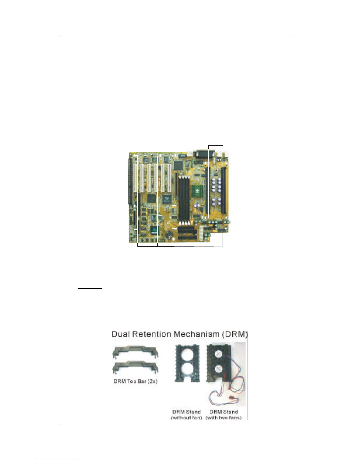
1. Mount the Motherboard on the Computer Chassis
You must first install the SY-D6IGA motherboard on the computer
chassis. The motherboard should be bare (without DRM and CPU)
and disconnected from any power source.
Position the motherboard with its mounting holes facing the
corresponding attachment holes on the chassis and tighten the
motherboard mounting screws.
2. Check the Parts Required for CPU Installation
q Part 1: DRM (Dual Retention Mechanism)
This motherboard is shipped with a DRM (Dual Retention
Mechanism) assembly to hold the single or dual Xeon™
processor in Slot2 #1 and Slot2 #2.
DRM Mounting Holes
Chassis Mounting Holes
Page 15
Hardware Setup SY-D6IGA
11
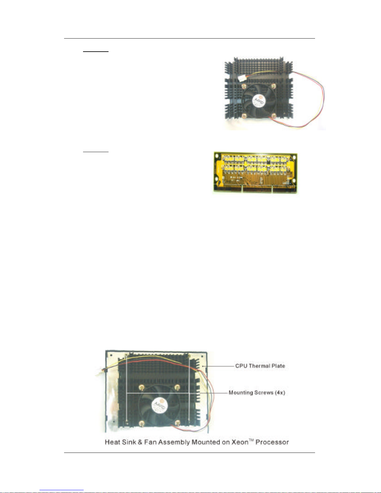
FSB Termination Card
(To be inserted in Slot2 #2)
q Part 2: CPU Heat Sink & Fan
SOYO has also included a heavyduty Heat Sink & Fan assembly for
better heat dissipation of the CPU.
We recommend that you use this
instead of the heat sink that comes
with your CPU.
q Part 3: FSB Termination Card
The FSB (Front Side Bus)
Termination Card must be
inserted in the unoccupied Slot2
connector #2 in a Single processor
configuration. If you install only one
processor, fit it in Slot2 #1, and
insert the FSB Termination Card in
the available Slot2 #2.
3. Mount the CPU Heat Sink & Fan Assembly
The CPU Heat Sink & Fan assembly provided by SOYO provides
better heat dissipation capability. Remove the original heat sink at
the back of the CPU SEC cartridge and affix SOYO’ s Heat Sink &
Fan assembly by securing the four mounting screws to the CPU’ s
thermal plate.
Page 16
Hardware Setup SY-D6IGA
12
4. Install the DRM Assembly
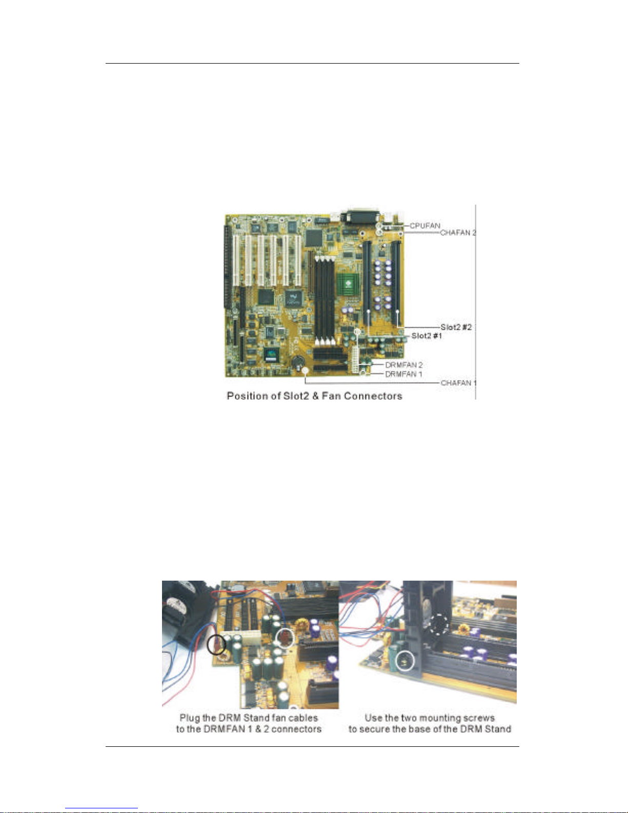
4(a) Locate Slot2 #1 & Slot2 #2 connectors and the DRM
mounting holes on the motherboard. Note that Slot2 #1 is
located closer to the middle of the motherboard while Slot2
#2 is situated near the edge of the board.
4(b) Attach the two fan cables of the DRM Stand (the one
equipped with 2 fans) to the fan power connectors labeled
DRMFAN 1 & 2 on the motherboard.
4(c) Affix this DRM Stand (the one equipped with 2 fans) to the
motherboard and then fix the DRM Stand by securing two
DRM mounting screws at the base of the DRM Stand to
the chassis.
Page 17
Hardware Setup SY-D6IGA
13
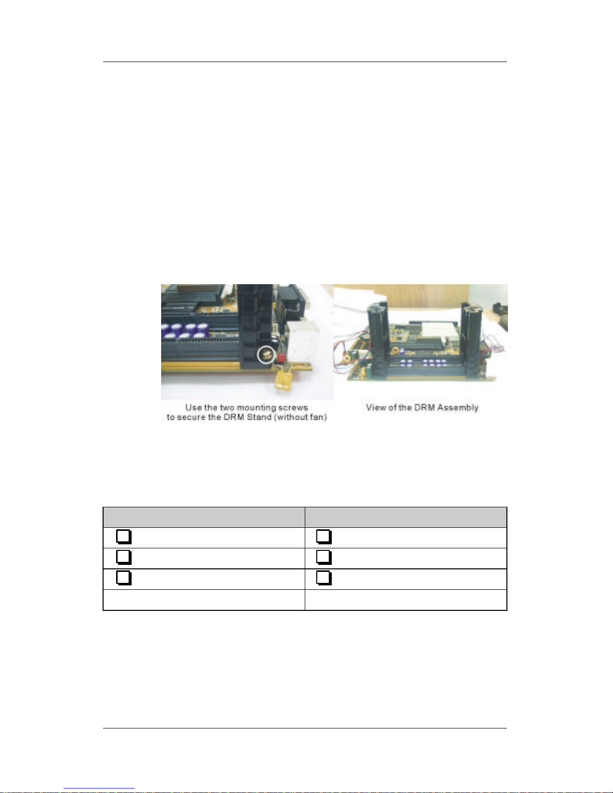
4(d) Mount the second DRM Stand (the one without fans)
opposite from the DRM fans (between the back panel
connectors and Slot2 sockets) and use two DRM mounting
screws to secure its base to the motherboard.
Note:If your system is using two chassis cooling fans, plug
the second fan cable to the chassis fan power connector
labeled CHAFAN 2, now. Once the second DRM Stand is
mounted, it will block the CHAFAN 2 connector, providing
insufficient clearance to either attach or remove the fan
power connector cable.
5. Install the First Processor in Slot2 #1
Record the working frequency and specification number of your
CPU that should be clearly marked on the CPU cover.
Pentium® II Xeon™ Processor Pentium® III Xeon™ Processor
400 MHz (100 x 4.0) 500 MHz (100 x 5.0)
450 MHz (100 x 4.5) 550 MHz (100 x 5.5)
S/N: S/N:
Page 18
Hardware Setup SY-D6IGA
14
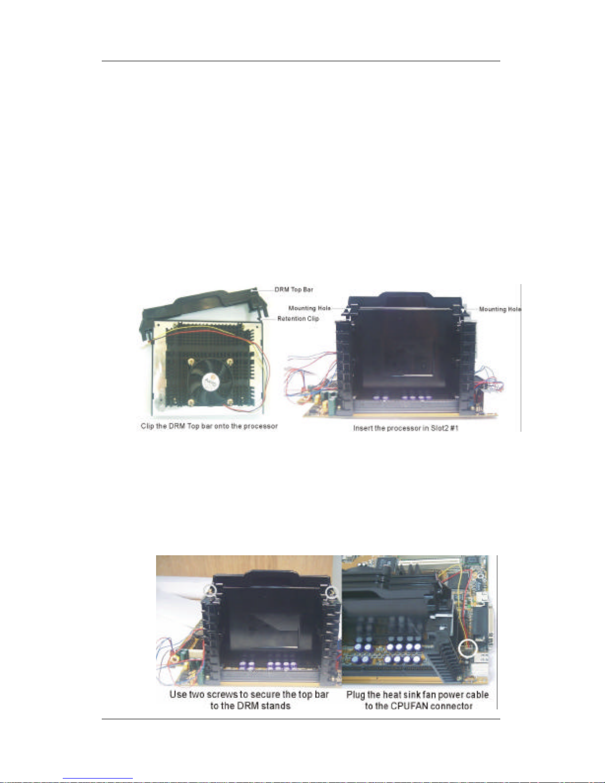
5(a) Clip the DRM Top onto the processor with the DRM Top
mounting holes facing away from the processor’ s heat sink
assembly.
5(b) Slide-in the processor into the DRM Assembly and insert it
in Slot2 #1, while making sure that the heat sink assembly
is facing towards the center of the motherboard.
Important: The Slot2 connector is directionally keyed, and
the processor will not go in unless it is properly oriented,
as shown in the figure.
5(c) Secure the DRM Top bar to both DRM stands by using two
mounting screws.
5(d) Connect the processor cooling fan cable to the CPU fan
power connector labeled CPUFAN on the motherboard.
Page 19

Hardware Setup SY-D6IGA
15
6. (Dual Processor Configuration)
Install the Second Processor in Slot2 #2
If you are installing a second processor in Slot2 #2, apply the same
procedure as in step 5. However, in step 5(a), clip the DRM Top onto
the processor with the mounting holes facing towards the heat sink.
Notice 1: When installing two processors, make sure the front side
bus and working frequency are identical for both processors. Do
NOT install different types of CPU at the same time, for example,
Pentium® II Xeon™ (400/450 MHz) and Pentium® III Xeon™
(500/550 MHz) processors may not work properly when installed
together in a dual configuration. We strongly recommend using two
processors with the same specification number in dual processor
configuration.
Notice 2: If two processors are installed in the DRM assembly, then
the clearance between processors will be insufficient and not allow
the use of a heat sink & fan assembly on the second processor (the
one installed in Slot2 #2). Cooling of the second processors will be
provided by the two DRM fans. If you install a heat sink on the
second processor, only use a narrow gage heat sink so as not to
obstruct the flow of air between the two processors.
7. (Single Processor Configuration)
Install the Termination Card in Slot2 #2
If only one processor is installed in your system, you are required to
insert the FSB Termination Card in the available Slot2 #2.
Note: If you are using a single processor, you must install the
processor in Slot 2 #1, then insert the Termination Card in Slot 2
#2, in this order.
Page 20

Hardware Setup SY-D6IGA
16
7(a) Insert the termination card in Slot2 #2, while making sure
that the two notches at the base of the card align perfectly
with the keys in Slot2 #2 connector.
Important: The Slot2 connector is directionally keyed, and
the termination card will not go in unless it is properly
oriented, as shown in the figure.
Page 21
Hardware Setup SY-D6IGA
17
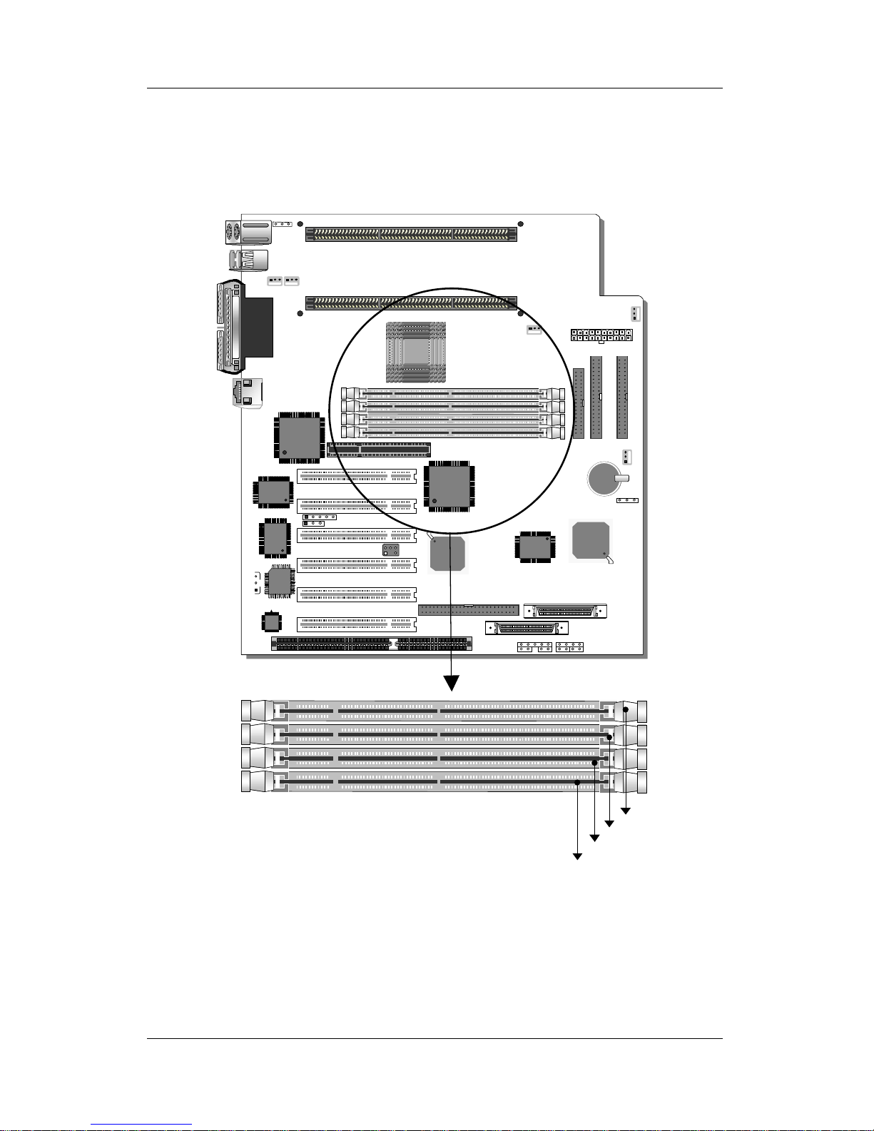
Step 2. SDRAM Memory Module Installation
This motherboard features 4 x DIMM Banks for 168-pin 3.3V
unbuffered and registered DIMM modules.
DIMM 1
DIMM 2
DIMM 3
DIMM 4
Page 22
Hardware Setup SY-D6IGA
18
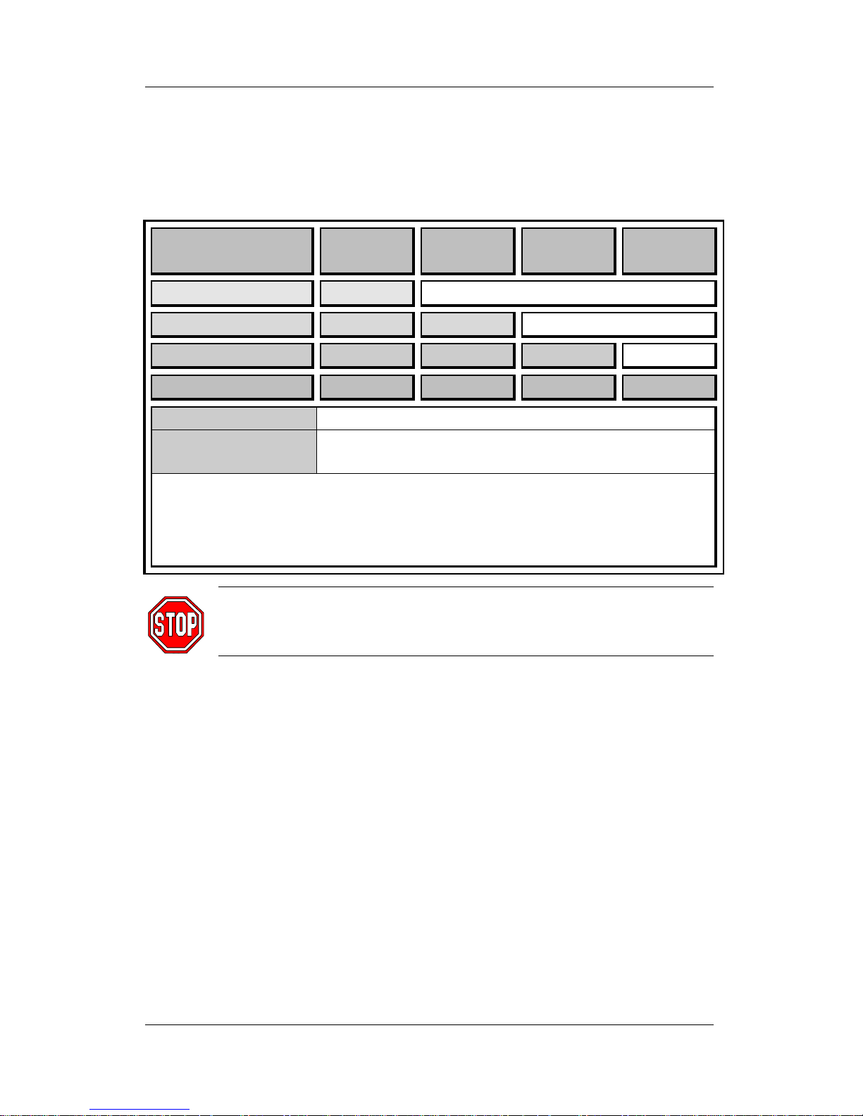
Your board comes with four DIMM sockets, providing support for up
to 2GB of main memory using DIMM modules from 8MB to 512MB.
Use only 8ns (100MHz, PC100 compliant) or faster memory.
Memory Configuration
Number of
Memory Modules
DIMM 1 DIMM 2 DIMM 3 DIMM 4
1
1
st
2
1
st
2
nd
3
1
st
2
nd
3
rd
4
1
st
2
nd
3
rd
4
th
RAM Type
SDRAM
Memory Module
Size (MB)
8/16/32/64/128/256/512 Mbytes
Notice 1: 256 & 512 MB memory modules only available on PC registered DIMM.
Notice 2: Always install memory modules in the order prescribed in this table.
Notice 3: Do not install unbuffered and registered memory modules together.
Important: It is of prime importance that you install DIMM
modules as outlined in the table above in order to preserve
signal integrity on 100MHz front side bus systems.
Step 3. IDE Device Installation (HDD, CD-ROM)
This motherboard offers two primary and secondary IDE device
connectors (IDE1, IDE2.) It can support up to four high-speed HDD
or CD-ROM.
Connect one side of the 40-pin flat cable to the IDE device (HDD or
CD-ROM) and plug the other end to the primary (IDE1) or secondary
(IDE2) directionally keyed IDE connector on the motherboard.
This motherboard can support up to four HDDs.
Page 23
Hardware Setup SY-D6IGA
19
Step 4. Floppy Drive Installation
The system supports 5 possible floppy drive types: 720 KB, 1.2 MB,
1.44 MB, 2.88 MB, and LS-120. In addition, this motherboard
supports a 3-mode (720KB/1.2MB/1.44MB) floppy commonly used
in Japan.
Connect one side of the 34-pin flat cable to the floppy drive and plug
the other end to the floppy drive connector on the motherboard.
This motherboard can support up to 2 floppy drives.
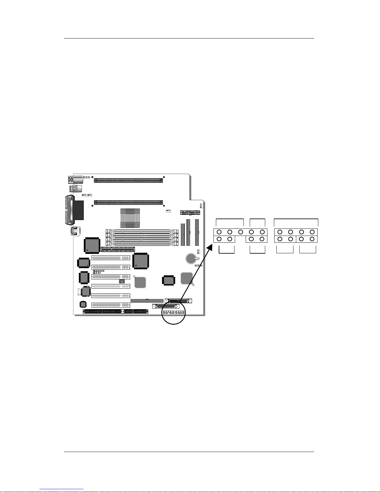
Step 5. Front Panel Connections
Plug the computer case's front panel devices to the corresponding
headers on the motherboard.
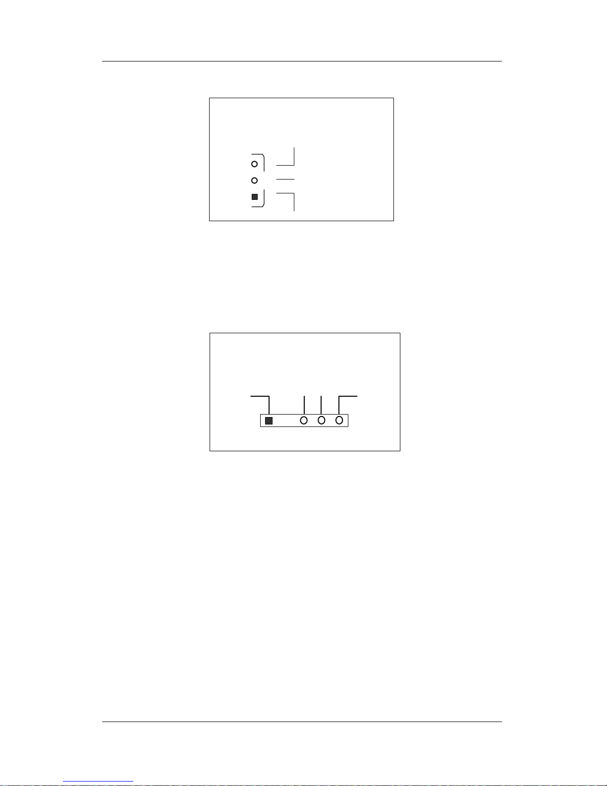
1. Power LED & KeyLock
Plug the Power LED cable into the 5-pin Keylock header.
Some systems may feature a KeyLock function with a front panel switch
for enabling or disabling the keyboard. Connect the KeyLock switch to
the 5-pin Keylock header on the motherboard, according to the following
pin assignment: pin 1,3 are for Power LED and pin 4,5 are for Keylock.
PWRBT HDD LEDTurbo
LED
Reset
_
+_+_+_+
SpeakerKeylock
Power
LED
Page 24

Hardware Setup SY-D6IGA
20
2. Reset
Plug the Reset push-button cable into the 2-pin Reset header on the
motherboard. Pushing the Reset button on the front panel will cause
the system to restart the boot-up sequence.
3. Speaker
Attach the 4-pin PC speaker cable from the case to the Speaker
header on the motherboard.
4. Turbo LED
Connecting the 2-pin Turbo LED cable to the corresponding Turbo
LED header will cause the LED to light whenever the system is in
Turbo mode.
The manufacturer has permanently set this motherboard in Turbo
mode due to most hardware and software compliance to turbo
mode.
5. IDE LED
Attach the 2-pin IDE device LED cable to the corresponding IDE
LED header on the motherboard. This will cause the LED to lighten
when an IDE (HDD, CD-ROM) device is active.
6. ATX Power On/Off Switch
Attach the 2-pin momentary type switch to the PWRBT header for
turning On or Off your ATX power supply.
Page 25
Hardware Setup SY-D6IGA
21
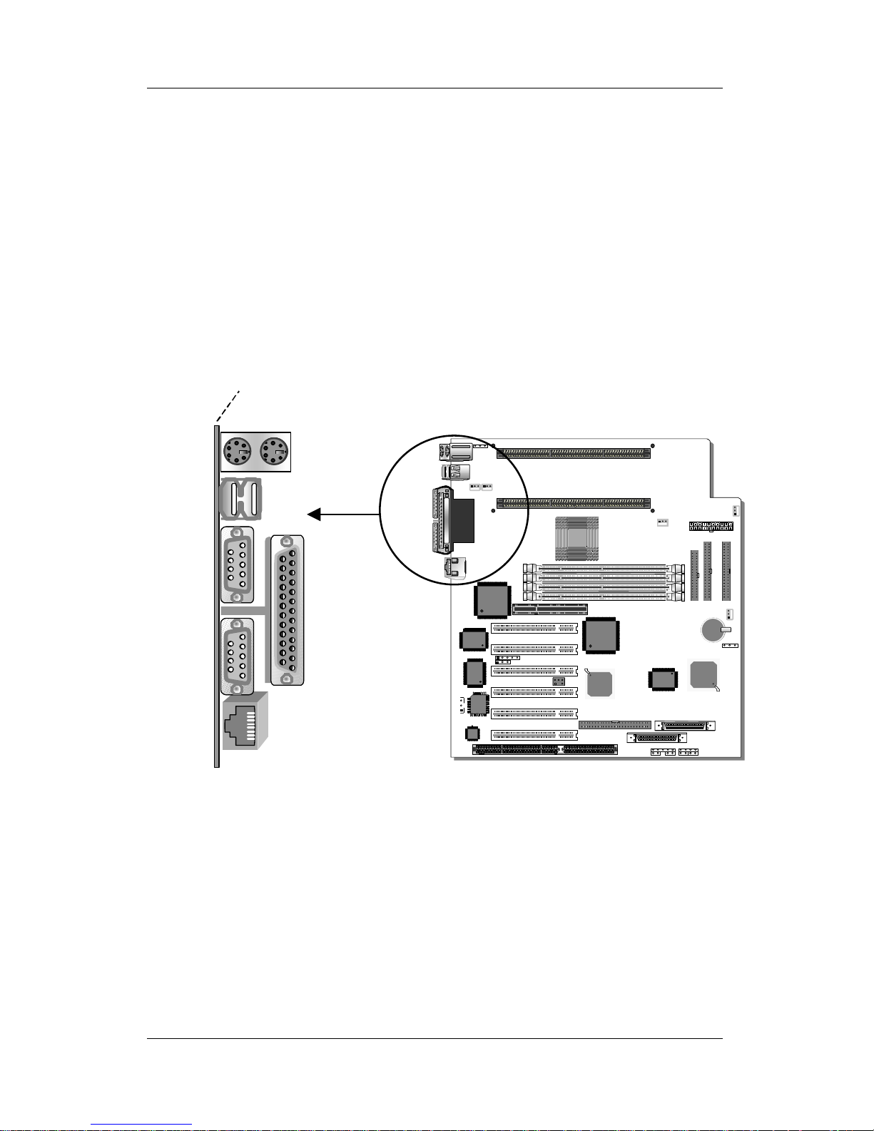
Step 6. Back Panel Connections
All external devices such as the PS/2 keyboard, PS/2 mouse, printer,
modem, USB can be plugged directly onto the motherboard back
panel.
Only after you have fixed and locked the motherboard to the
computer case can you start connecting the external peripheral
devices.
When connecting an external device, use the following figure to
locate and identify which back panel connector to plug the device to.
1. Onboard Serial Ports COM1/COM2
External peripherals that use serial transmission scheme include:
- serial mouse,
- and modem.
Plug the serial device cables directly into the COM1/COM2 9-pin
male connectors located at the rear panel of the motherboard.
Ethernet
RJ-45
PRT
USB 2
PS/2 KB
Connector
PS/2 Mouse
Connector
COM 2
COM 1
USB 1
Page 26

Hardware Setup SY-D6IGA
22
2. Parallel Port PRT
This parallel port is used to connect the printer or other parallel
devices.
Plug the parallel device cable into the 25-pin female connector
located at the rear panel of the motherboard.
3. PS/2 Keyboard
Plug the keyboard jack directly into the 6-pin female PS/2 keyboard
connector located at the rear panel of the motherboard.
4. PS/2 Mouse
Similarly, plug the mouse jack directly into the 6-pin female PS/2
mouse connector.
5. Universal Serial Bus USB1/USB2
This motherboard provides two USB ports for your additional
devices. Plug the USB device jack into the available USB connector
USB1 or USB2.
- USB devices under Win98 are allowed.
- With Win95, use the flow UHCI specifications.
Step 7. Other Connections
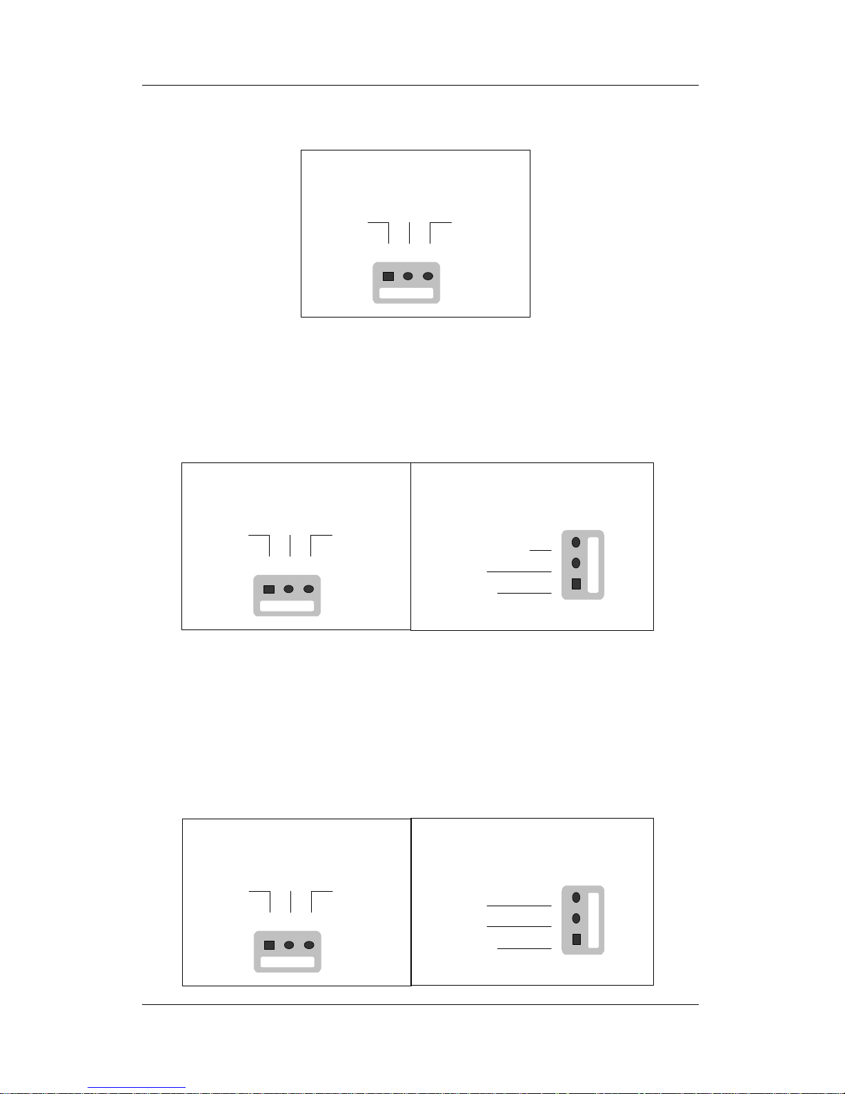
1. Wake-On-LAN (WOL)
Attach the 3-pin connector from the LAN card which supports the
Wake-On-LAN (WOL) function to the JP44 header on the
motherboard. This WOL function lets users wake up the connected
computer through the LAN card.
Page 27
Hardware Setup SY-D6IGA
23
Please install according to the following pin assignment:
2. Infrared (IR1)
Plug the 5-pin infrared device cable to the IR1 header. This will
enable the infrared transfer function. This motherboard meets both
the ASKIR and HPSIR specifications.
Please install according to the following pin assignment:
Step 8. Cooling Fan Installation
1. CPU Cooling Fan (CPUFAN)
After you have seated the first processor properly in Slot2 #1, attach
the 3-pin fan cable from the CPU Heat & Fan Assembly to the
corresponding CPUFAN connector on the motherboard.
The CPU fan will stop when the system enters into Suspend Mode.
(Suspend mode can be enabled from the BIOS Setup Utility,
[POWER MANAGEMENT] menu.)
1 2 3 4 5
VCC IRRX GND IRTX
Infrared (IR) Connector
IR1 Pin Assignment
Wake-On-LAN
JP44 Pin Assignment
GND
1
2
3
5VSB
MP - Wake-up
Page 28
Hardware Setup SY-D6IGA
24
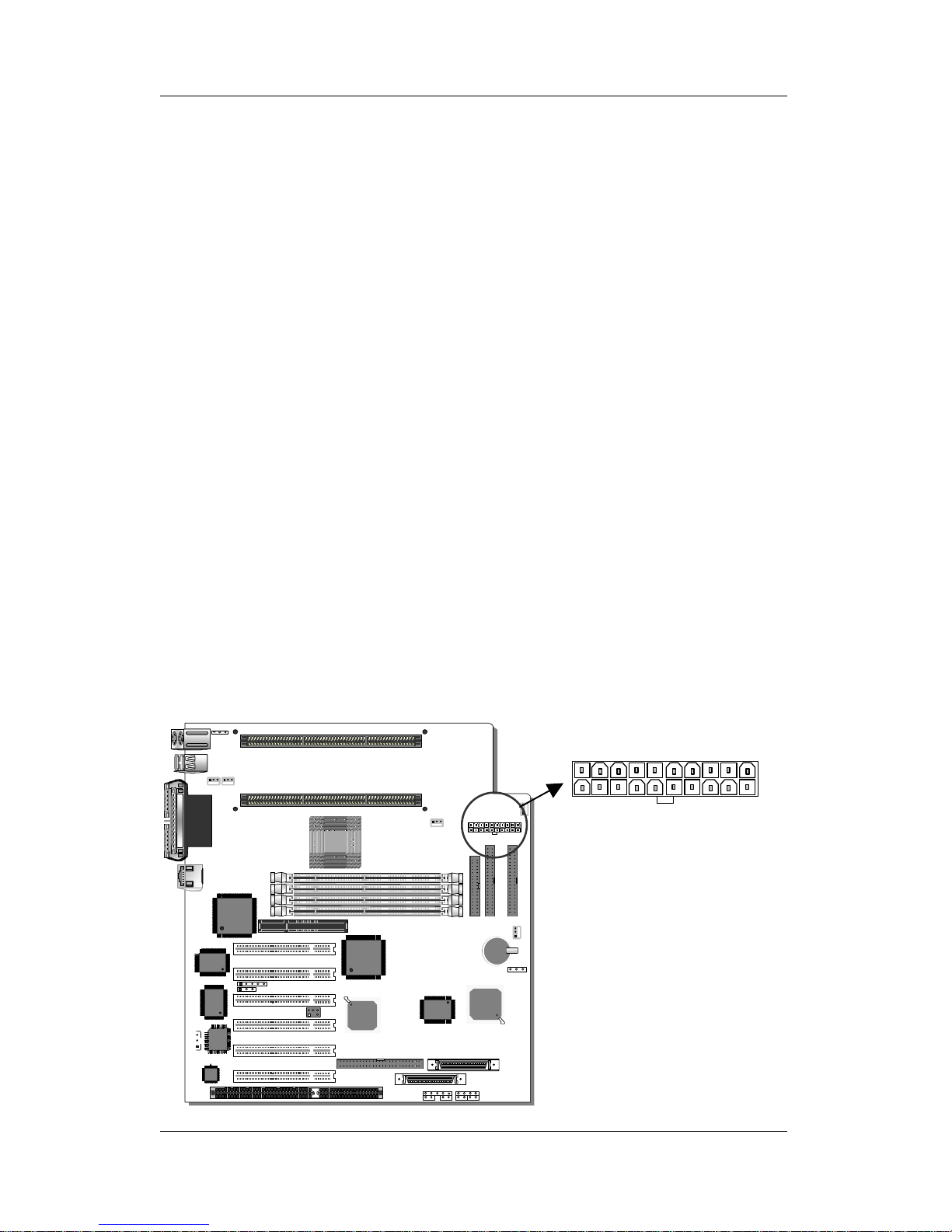
To avoid damage to the system, install according to the following pin
assignment:
2. DRM Cooling Fans (DRMFA1, DRMFA2)
Attach the two fan cables from the DRM Assembly to the fan power
connectors labeled DRMFAN 1 & 2 on the motherboard. Install
according to the following pin assignment:
3. Chassis Cooling Fans (CHAFA1, CHAFA2)
Some chassis also include one to two cooling fans. This
motherboard features two connectors (CHAFA1, CHAFA2) to
provide 12V power to the chassis fans. Connect the cables from the
chassis fans to the 3-pin connectors on the motherboard, according
to the following pin assignment:
1 2 3
GND 12V SENSOR
Slot2 #1
CPU Cooling Fan
CPUFAN
Pin Assignment
1 2 3
GND 12V SENSOR
DRM Assembly Cooling Fan
DRMFA2
Pin Assignment
DRM Assembly Cooling Fan
DRMFA1
Pin Assignment
1
2
3
GND
12V
SENSOR
1 2 3
GND 12V
Chassis Cooling Fan
CHAFA2
Pin Assignment
NC
Chassis Cooling Fan
CHAFA1
Pin Assignment
1
2
3
GND
12V
NC
Page 29
Hardware Setup SY-D6IGA
25
Step 9. AGP VGA Card
Insert the AGP VGA card into the AGP slot. Then connect the
monitor information cable to the AGP card back plane external
connector.
Follow the manufacturer's instructions to perform the AGP VGA
drivers installation.
Other Display Cards: Insert other types of VGA cards into the PCI
or ISA expansion slots according to card specifications.
Step 10. PCI Audio Card
Some PCI soundcards require a PC-PCI DMA channel. Attach the
5-pin cable from your Creative sound blaster PCI audio card to the
SB-LINK™ header on the motherboard. The SB-LINK™ will forward
requests for legacy DMA channel to the PCI Bus.
Step 11. ATX Power Supply
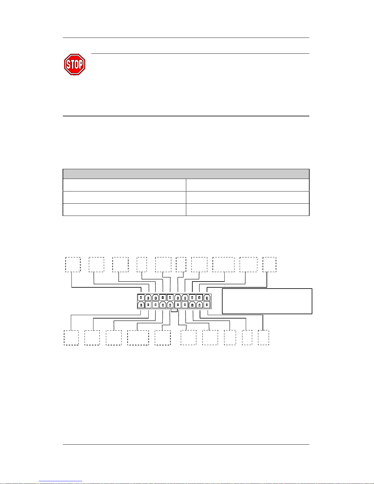
Plug the connector from the power directly into the 20-pin male ATX
PW connector on the motherboard, as shown in the following figure.
ATX Power
Page 30
Hardware Setup SY-D6IGA
26
Warning: Follow these precautions to preserve your
motherboard from any remnant currents when connecting to
ATX power supply:
Turn off the power supply and unplug the power cord of the
ATX power supply before connecting to ATX PW connector.
This motherboard requires a power supply with a "power good"
signal. Make sure the ATX power supply can meet the following
power requirements:
Motherboard Power Requirements
+3.3V
≥
20.0A -5V
≥
0.2A
+5V
≥
35.0A +12V
≥
5.5A
+5VSB
≥
1A -12V
≥
0.25
Please install the ATX power according to the following pin
assignment and power requirements:
3.3V 3.3V GND 5V GND 5V GND PW-0K 5VSB 12V
ATX Power
3.3V -12V GND PS-ON GND
GND GND -5V 5V 5V
Pay special care
to the directionality
Page 31
Hardware Setup SY-D6IGA
27
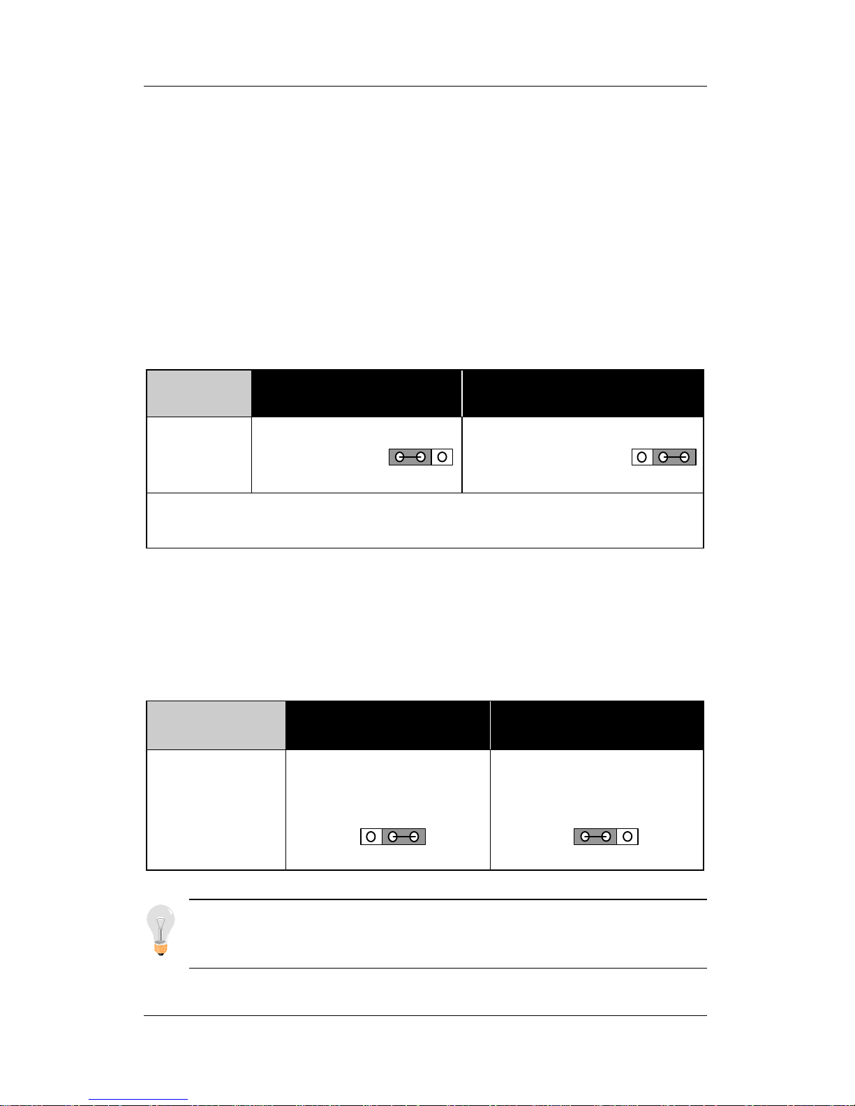
Step 12. CMOS Clearing (JP5)
After you have turned off your computer, clear the CMOS memory
by momentarily shorting pins 2-3 on jumper JP5, for a few seconds.
Then restore JP5 to the initial 1-2 jumper setting in order to recover
and retain the default settings.
After you have turned off your computer, clear the CMOS memory by
momentarily shorting pin 2-3 on jumper JP5 for at least 5 seconds. Then
permanently short pin 1-2 to retain new settings.
Jumper JP5 can be easily identified by its white colored cap.
CMOS
Clearing
Retain CMOS Data Clear CMOS Data
JP5
Setting
Short pin 1-2 to
retain the new
CMOS settings.
Short pin 2-3 for
at least 5 seconds
to clear the CMOS.
Note: You must unplug the ATX power cable from the ATX power
connector when performing the CMOS Clear operation.
Step 13. Power-On by PS/2 Keyboard Jumper (JP10)
You can choose to enable the Power-On by PS/2 Keyboard function
by shorting pin 2-3 on jumper JP10; otherwise, short pin 1-2 to
disable this function.
Power-On by
PS/2 Keyboard
Enable Disable
JP10 Setting
Short pin 2-3 to enable
the Power-On by PS/2
Keyboard function.
Short pin 1-2 to disable
the Power-On by PS/2
Keyboard function.
Note: When using the Power-On by PS/2 Keyboard function, please
make sure the ATX power supply can take at least 1A load on the
5V Standby lead (5VSB).
32132132132
1
Page 32
Hardware Setup SY-D6IGA
28
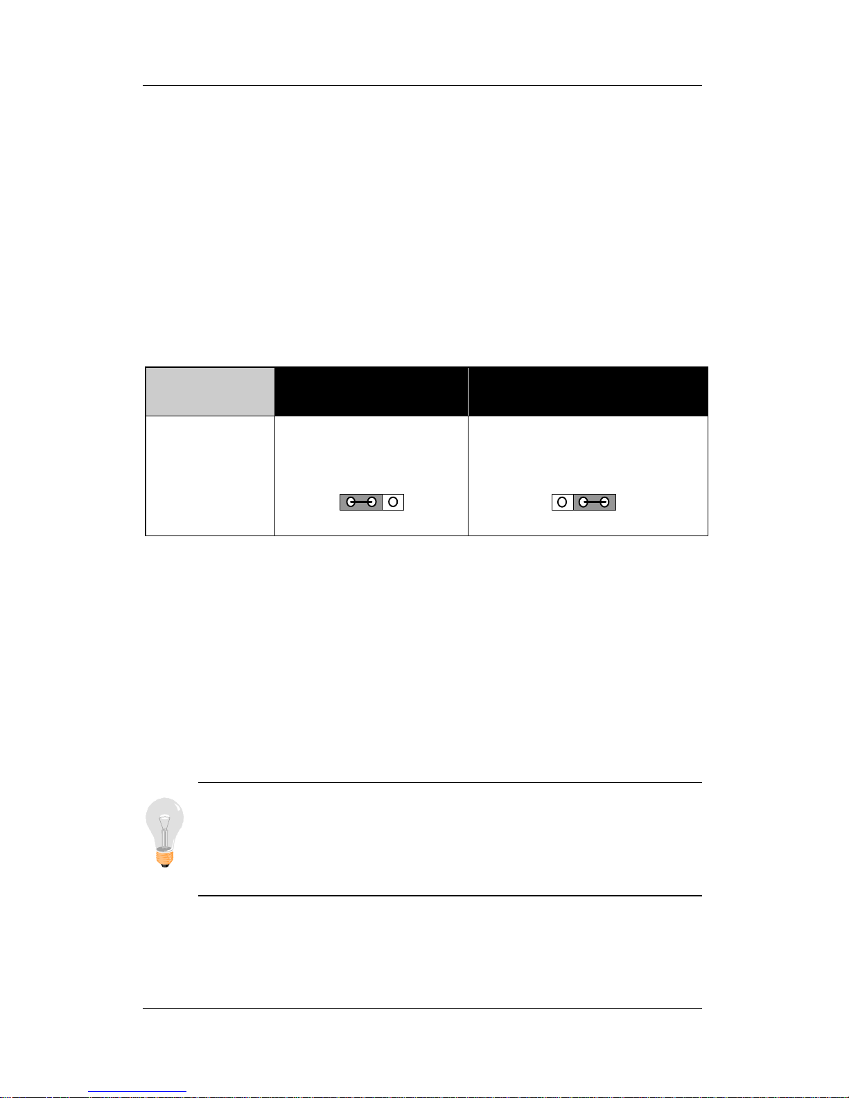
Step 14. Power Button Enable (JP11)
Your system can be powered on either by pressing the power switch
or by entering a system password at the prompt. (Note that the
system password can be configured in the BIOS “SOYO COMBO
Setup”).
In case you forget the system password, you will be denied access
to the system. To avoid this, you can short pin 1-2 on jumper JP11,
which will override the password and always enable the power
button function.
Power Button
Enable
Always Enable
The Power Button
Power Button Function
According to BIOS Setting
JP11 Setting
Short pin 1-2 to
always enable the
Power Button function.
Short pin2-3 for a
Power Button function
according to BIOS setting.
Step 15. Power On
You have now completed the hardware installation of your
motherboard successfully.
1. Turn the power on
2. To enter the BIOS Setup Utility, press the <DEL> key while the
system is performing the diagnostic checks,
Note: If you fail to enter the BIOS, wait until the boot up
sequence is completed. Then push the RESET button and
press <DEL> key again at the beginning of boot-up, during
diagnostic checks.
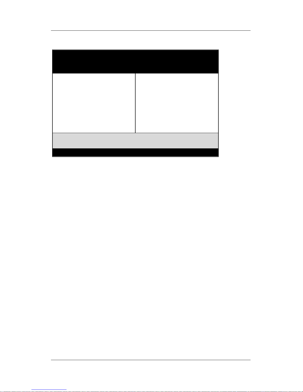
Repeat this operation until you get the following screen.
32132
1
Page 33
Hardware Setup SY-D6IGA
29
3. The BIOS Setup screen appears:
Step 16. Quick BIOS Setup
This motherboard does not use any hardware jumpers to set the
CPU frequency. Instead, CPU settings are software configurable
with the BIOS [SOYO COMBO SETUP]. The [SOYO COMBO
SETUP] menu combines the main parameters that you need to
configure, all in one menu, for a quick setup in BIOS.
After the hardware installation is complete, turn the power switch on,
then press the <DEL> key during the system diagnostic checks to
enter the Award BIOS Setup program. The CMOS SETUP UTILITY
will display on screen. Follow these steps to configure the CPU
settings.
1. Select [LOAD SETUP DEFAULT]
Select the “LOAD SETUP DEFAULT” menu and type “ Y” at the
prompt to load the BIOS optimal setup.
2. Select [STANDARD CMOS SETUP]
Set [Date/Time] and [Floppy drive type], then set [Hard Disk Type] to
“Auto”.
ROM PCI/ISA BIOS
CMOS SETUP UTILITY
AWARD SOFTWARE, INC.
SOYO COMBO SETUP
STANDARD CMOS SETUP
BIOS FEATURES SETUP
CHIPSET FEATURES SETUP
POWER MANAGEMENT SETUP
PNP/PCI CONFIGURATION
LOAD SETUP DEFAULTS
INTEGRATED PERIPHERALS
SUPERVISOR PASSWORD
USER PASSWORD
IDE HDD AUTO DETECTION
SAVE & EXIT SETUP
EXIT WITHOUT SAVING
Esc
F10
: Quit
: Save & Exit Setup
↑ ↓ → ←
(Shift) F2
: Select Item
: Change Color
Time, Date, Hard Disk Type…
Page 34
Hardware Setup SY-D6IGA
30
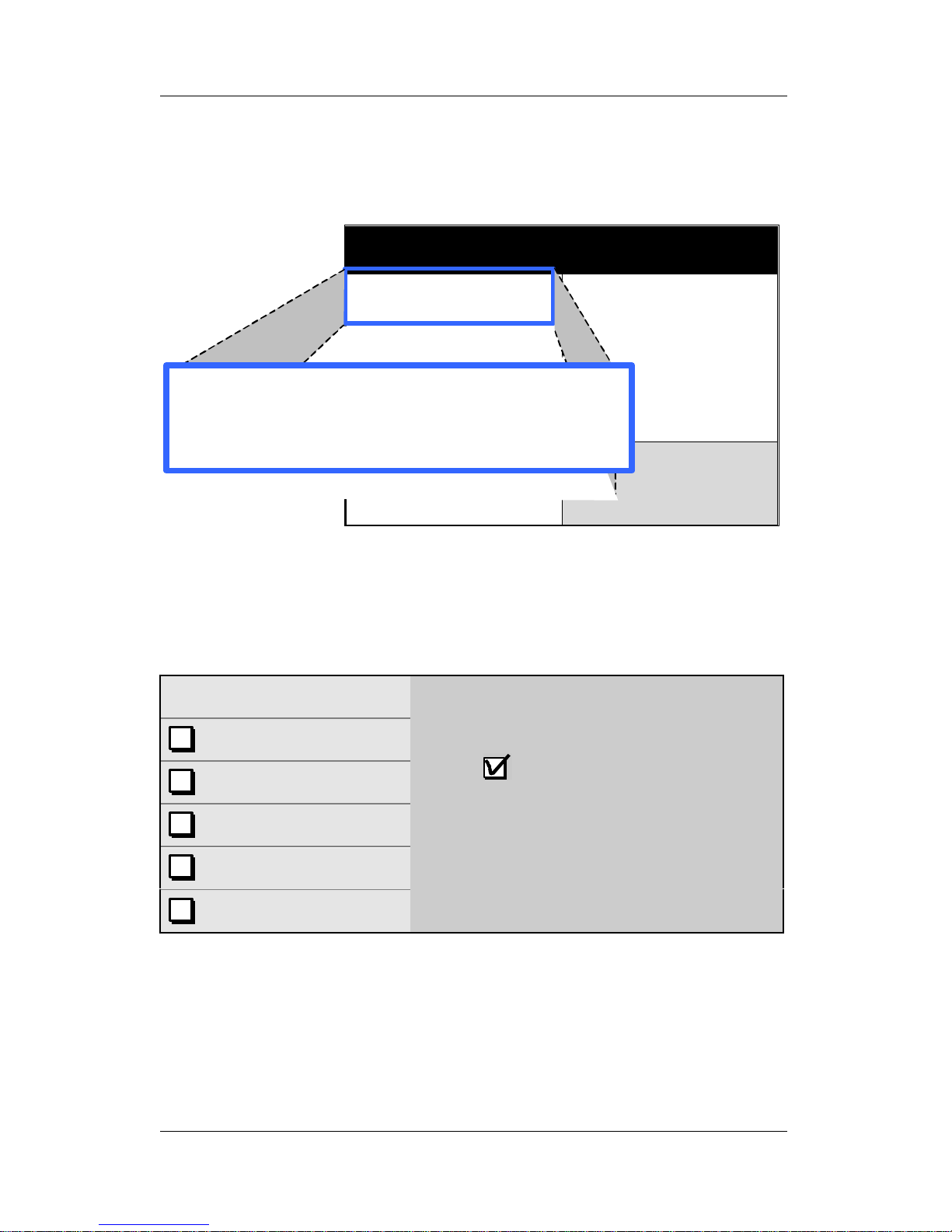
3. Select [SOYO COMBO SETUP]
Move the cursor to the [CPU Frequency] field to set the CPU
working frequency, as shown in the following display.
Available [CPU Speed] settings on your SY-D6IGA Motherboard are
detailed in the following table. If you set this field to [Manual], you
are then required to fill in the next two consecutive fields: (1) the
CPU Ratio, and (2) the CPU Frequency.
CPU Frequency
400MHz (100 x 4.0)
450MHz (100 x 4.5)
500MHz (100 x 5.0)
550MHz (100 x 5.5)
Select the working frequency of your
Xeon™ processor among these preset
values.
Note: Mark the checkbox that
corresponds to the working frequency
of your Xeon™ processor in case the
CMOS configuration should be lost.
You can also write your own frequency
combination in the space provided.
4. Select [SAVE & EXIT SETUP]
Press <Enter> to save the new configuration to the CMOS memory,
and continue the boot sequence.
ROM PCI/ISA BIOS
SOYO COMBO SETUP
AWARD SOFTWARE, INC.
CPU Speed
CPU Ratio
CPU Frequency
: Manual
: x 5 = 500 MHz
: 100 MHz
Boot Sequence : A,C,SCSI
Current CPU1 Temperature
Current CPU2 Temperature
Current CPUFAN1 Speed
Current CPUFAN2 Speed
Current CPUFAN3 Speed
: 29°C/84°F
: 29°C/84°F
: 4891 RPM
: 4891 RPM
: 6553 RPM
Quick Power On Self Test : Enabled
CPU1(V)
+3.3 V
+12 V
- 5 V
: 2.81 V
: 3.40 V
: 12.16V
: - 5.26V
CPU2(V)
+5 V
-12 V
: 2.81V
: 5.25V
: -12.15V
Current CPU1 Temperature
Current CPU2 Temperature
: 29°C/84°F
: 29°C/84°F
ESC
F1
F5
: Quit
: Help
: Old Values
↑ ↓ →
←
PU/PD/+/-
(Shift) F2
: Select Item
: Modify
: Color
POWER ON Function
KB Power ON Password
Hot Key Power ON
Soft-Off by PWR-BTTN
Power-On by Ring/LAN
Power-On by Alarm
: BUTTON ONLY
: Enter
: Ctrl-F1
: Instant-Off
: Enabled
: Disabled
F6F7: Load BIOS Defaults
: Load Setup Defaults
CPU Speed
CPU Ratio
CPU Frequency
: Manual
: x 5 = 500 MHz
: 100 MHz
Page 35

Hardware Setup SY-D6IGA
31
Step 17. Power Off
There are two possible ways to turn off the system:
1. Use the Shutdown command in the Start Menu of Windows
95/98 to turn off your computer.
2. Press the mechanical power-button and hold down for over 4
seconds, to shutdown the computer. If you press the powerbutton for less than 4 seconds, then your system will enter into
Suspend Mode.
Page 36

Hardware Setup SY-D6IGA
32
Troubleshooting at First Start
l What should I do if the motherboard refuses to start?
The 350MHz setting is used as default so whenever the BIOS
settings are erased or reset, the board will be able to boot up.
If the CPU speed was set too high and the motherboard refuses to
start up, you can always load the default values by pressing the [Ins]
key during boot up.
l Over-clocking may cause system malfunctions!
The SY-D6IGA motherboard provides over-clocking capability. Due
to the over-clocking setting your system may fail to boot up or hang
during run time. If this occurs, please perform the following steps to
recover your system from the abnormal situation:
1. Turn off system power. (If you use an ATX power supply, and
depending on your system, you may have to press the power
button for more than 4 seconds to shut down the system.)
2. Press and hold down the <Insert> key while turning on the
system power. Keep holding down the <Insert> key until you
see the message of the CPU type and frequency (133MHz or
200MHz) appear on screen.
3. Press the <Del> key during the system diagnostic checks to
enter the Award BIOS Setup program.
4. From the BIOS main menu, select [SOYO COMBO SETUP]
and move the cursor to the [CPU Frequency] field to set the
proper working frequency.
5. Select [Save & Exit SETUP] and press <Enter> to save the
configuration to the CMOS memory, and continue the boot
sequence.
Note: SOYO does not guarantee system stability if the user
over clocks the system. Any malfunctions due to over-clocking
are not covered by the warranty.
Page 37
BIOS Setup Utility SY-D6IGA
33
Chapter 3
BIOS SETUP UTILITY
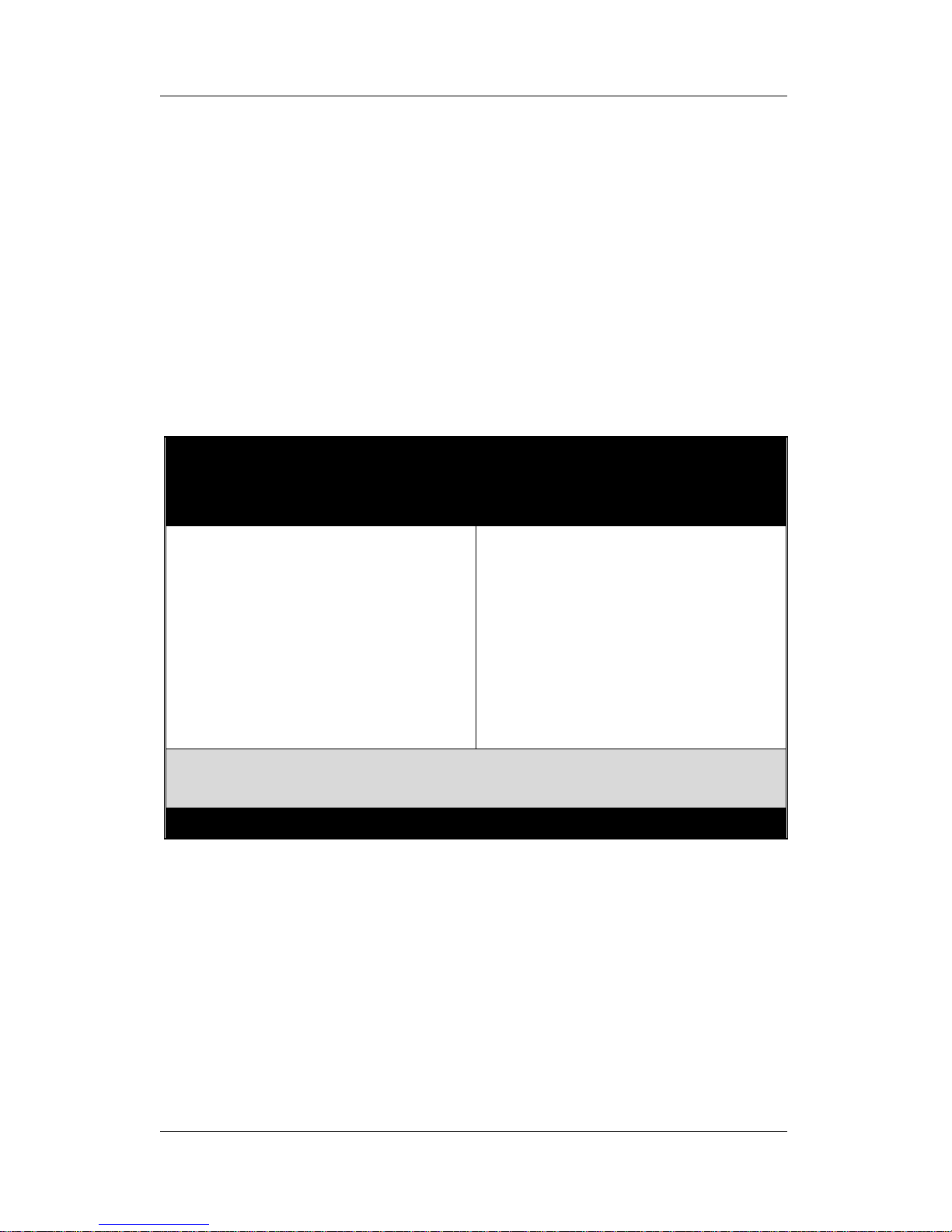
This motherboard's BIOS setup program uses the ROM PCI/ISA
BIOS program from Award Software Inc.
To enter the Award BIOS program's Main Menu:
1. Turn on or reboot the system.
2. After the diagnostic checks, press the [Del] key to enter the
Award BIOS Setup Utility.
Selecting items
l Use the arrow keys to move between items and select fields.
l From the Main Menu press arrow keys to enter the selected
submenu.
Modifying selected items
l Use the [Up]/[Down] keys to modify values within the selected
fields. Some fields let you enter values directly.
ROM PCI/ISA BIOS
CMOS SETUP UTILITY
AWARD SOFTWARE, INC.
SOYO COMBO SETUP
STANDARD CMOS SETUP
BIOS FEATURES SETUP
CHIPSET FEATURES SETUP
POWER MANAGEMENT SETUP
PNP/PCI CONFIGURATION
LOAD SETUP DEFAULTS
INTEGRATED PERIPHERALS
SUPERVISOR PASSWORD
USER PASSWORD
IDE HDD AUTO DETECTION
SAVE & EXIT SETUP
EXIT WITHOUT SAVING
Esc
F10
: Quit
: Save & Exit Setup
↑ ↓ → ←
(Shift) F2
: Select Item
: Change Color
Time, Date, Hard Disk Type…
Page 38
BIOS Setup Utility SY-D6IGA
34
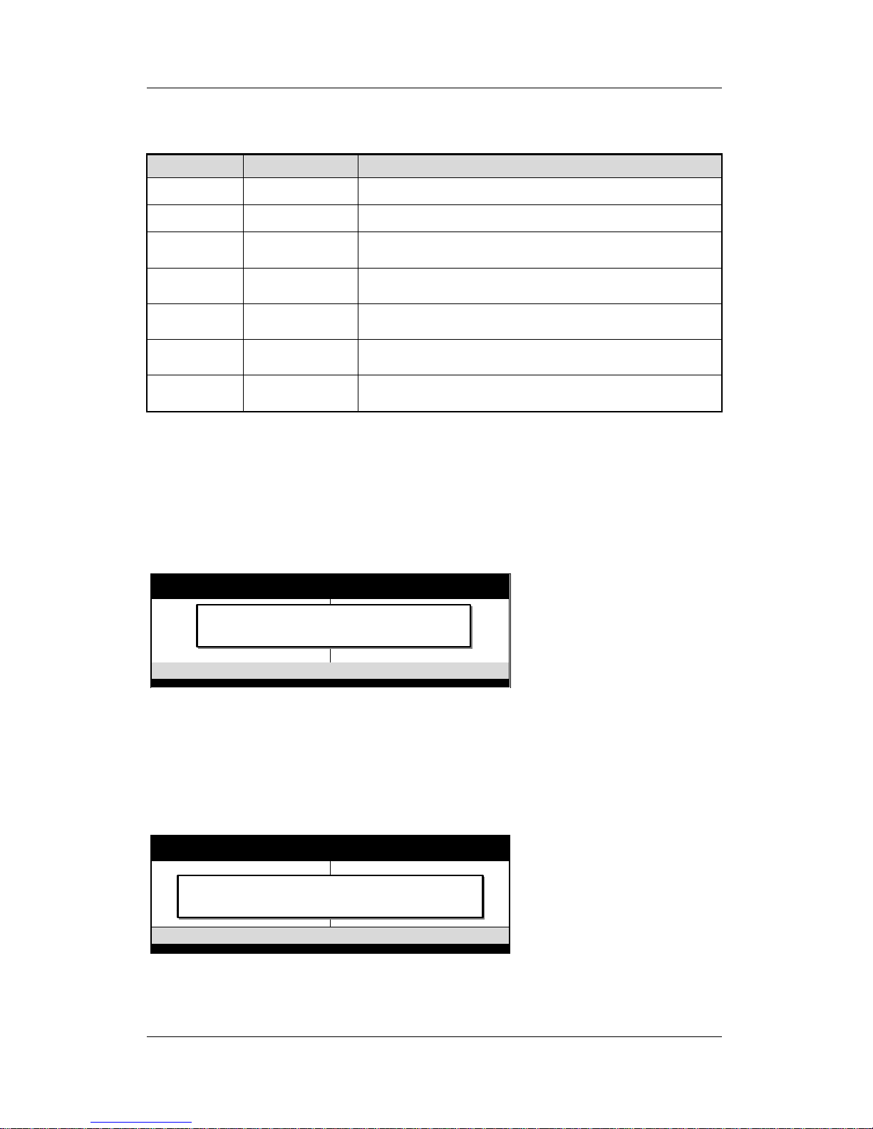
Hot Keys: Function keys give you access to a group of commands
throughout the BIOS utility.
Function Command Description
F1
Help Gives the list of options available for each item.
Shift F2
Color Change the color of the display window.
F5
Old values Restore the old values. These are the values that
the user started the current session with.
F6
Load BIOS
Defaults
Loads all options with the BIOS Setup default
values.
F7
Load Setup
Defaults
Loads all options with the Power-On default values.
F10
Save & Exit
Setup
Saves your changes and reboots the system.
[Esc]
Quit Lets you return at anytime and from any location to
the Main Menu.
SAVE AND EXIT SETUP
Select the [SAVE & EXIT SETUP] option from the Main Menu to
save data to CMOS and exit the setup utility. This option saves all
your changes and causes the system to reboot.
Type [Y] to save the
changes and exit or [N] to
return to the Main Menu
and keep current values.
EXIT WITHOUT SAVING
Selecting the [EXIT WITHOUT SAVING] option allows you to
abandon all data and exit setup, therefore ignoring all your changes.
Type [Y] to abandon
changes and exit or [N] to
return to the Main Menu
and keep current values.
ROM PCI/ISA BIOS
CMOS SETUP UTILITY
AWARD SOFTWARE, INC.
STANDARD CMOS SETUP
BIOS FEATURES SETUP
CHIPSET FEATURES SETUP
POWER MANAGEMENT SETUP
PNP/PCI CONFIGURATION
LOAD SETUP DEFAULTS
LOAD BIOS DEFAULTS
INTEGRATED PERIPHERALS
SUPERVISOR PASSWORD
USER PASSWORD
IDE HDD AUTO DETECTION
SAVE & EXIT SETUP
EXIT WITHOUT SAVING
Esc
F10
: Quit
: Save & Exit Setup
↑ ↓ → ←
(Shift) F2
: Select Item
: Change Color
Time, Date, Hard Disk Type…
SAVE to CMOS and EXIT (Y/N)? _
ROM PCI/ISA BIOS
CMOS SETUP UTILITY
AWARD SOFTWARE, INC.
STANDARD CMOS SETUP
BIOS FEATURES SETUP
CHIPSET FEATURES SETUP
POWER MANAGEMENT SETUP
PNP/PCI CONFIGURATION
LOAD SETUP DEFAULTS
LOAD BIOS DEFAULTS
INTEGRATED PERIPHERALS
SUPERVISOR PASSWORD
USER PASSWORD
IDE HDD AUTO DETECTION
SAVE & EXIT SETUP
EXIT WITHOUT SAVING
Esc
F10
: Quit
: Save & Exit Setup
↑ ↓ → ←
(Shift) F2
: Select Item
: Change Color
Time, Date, Hard Disk Type…
Quit Without Saving (Y/N)? _
Page 39
BIOS Setup Utility SY-D6IGA
35
3-1 SOYO COMBO SETUP
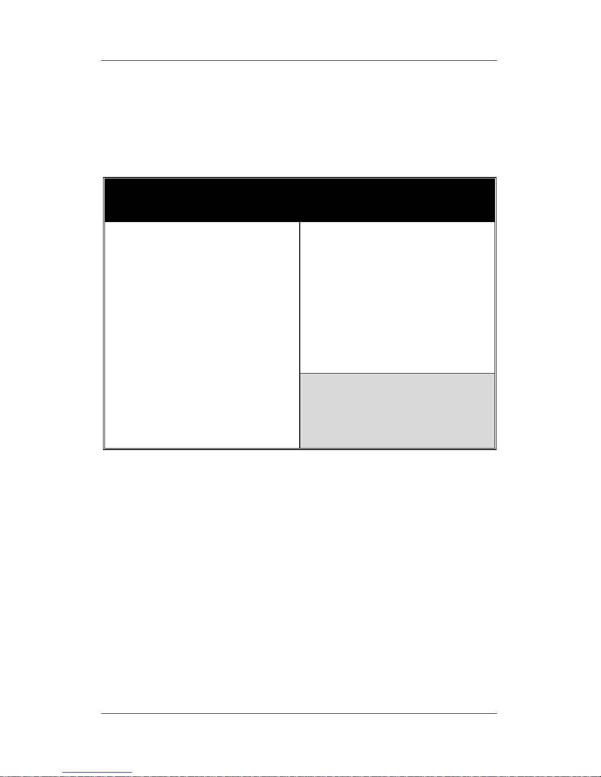
This motherboard does not use any hardware jumpers to set the
CPU frequency. Instead, CPU settings are software configurable
with the BIOS [SOYO COMBO SETUP].
After the hardware installation is complete, turn the power switch on,
then press the <DEL> key during the system diagnostic checks to
enter the Award BIOS Setup program. The CMOS SETUP UTILITY
will display on screen. Then, select the [SOYO COMBO SETUP]
option from the main menu and press the <Enter> key.
The [SOYO COMBO SETUP] menu combines the main parameters
that you need to configure, all in one menu, for a quick setup in
BIOS.
ROM PCI/ISA BIOS
SOYO COMBO SETUP
AWARD SOFTWARE, INC.
CPU Speed
CPU Ratio
CPU Frequency
: Manual
: x 5 = 500 MHz
: 100 MHz
Boot Sequence : A,C,SCSI
Current CPU1 Temperature
Current CPU2 Temperature
Current CPUFAN1 Speed
Current CPUFAN2 Speed
Current CPUFAN3 Speed
: 29
C/84
F
: 29
C/84
F
: 4891 RPM
: 4891 RPM
: 6553 RPM
Quick Power On Self Test : Enabled
CPU1(V)
+3.3 V
+12 V
- 5 V
: 2.81 V
: 3.40 V
: 12.16V
: - 5.26V
CPU2(V)
+5 V
-12 V
: 2.81V
: 5.25V
: -12.15V
Current CPU1 Temperature
Current CPU2 Temperature
: 29
C/84
F
: 29
C/84
F
ESC
F1
F5
: Quit
: Help
: Old Values
PU/PD/+/-
(Shift) F2
: Select Item
: Modify
: Color
POWER ON Function
KB Power ON Password
Hot Key Power ON
Soft-Off by PWR-BTTN
Power-On by Ring/LAN
Power-On by Alarm
: BUTTON ONLY
: Enter
: Ctrl-F1
: Instant-Off
: Enabled
: Disabled
F6F7: Load BIOS Defaults
: Load Setup Defaults
Page 40
BIOS Setup Utility SY-D6IGA
36
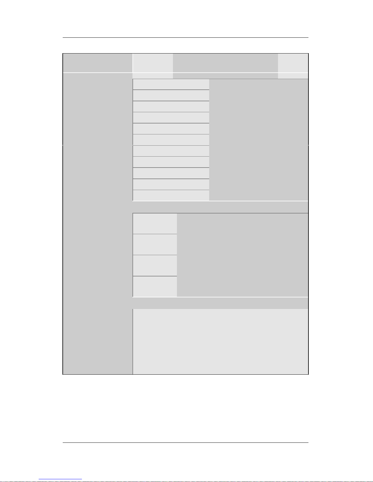
3-1.1 Quick CPU Speed Settings
Quick CPU
Speed Settings
Setting Description Note
Manual
350MHz (100 x 3.5)
400MHz (100 x 4)
450MHz (100 x 4.5)
500MHz (100 x 5)
550MHz (100 x 5.5)
600MHz (100 x 6)
650MHz (100 x 6.5)
700MHz (100 x 7)
750MHz (100 x 7.5)
CPU Speed
(*Default)
800MHz (100 x 8)
Select the working
frequency of your
Pentium® II Xeon™ or
Pentium® III Xeon™
processor among these
preset values.
Note: Setting this field to
[Manual] requires you to
fill in the next two
consecutive fields:
(1) the [CPU Ratio],
(2) the [CPU Frequency].
If [CPU Speed] field is set to [Manual]
103 MHz
112 MHz
133 MHz
CPU Frequency
100 MHz
Select the host clock of your Pentium
®
II Xeon™ or Pentium® III Xeon™
processor among these values.
Note: For the GX chipset, the FSB
specification is 100MHz. The
system stability is not guaranteed
for other frequencies due to the
limitations of this chipset.
If [CPU Speed] field is set to [Manual]
CPU Ratio
After you have selected the host clock, choose the
right multiplier for the CPU. Options are: [2, 2.5, 3.,
3.5, 4, 4.5, 5, 5.5, 6, 6.5, 7, 7.5, 8]. The CPU
frequency is then defined as [host clock
freq.]x[multiplier], and should match the working
frequency of your Pentium® II Xeon™
or Pentium® III Xeon™ processor.
Page 41
BIOS Setup Utility SY-D6IGA
37
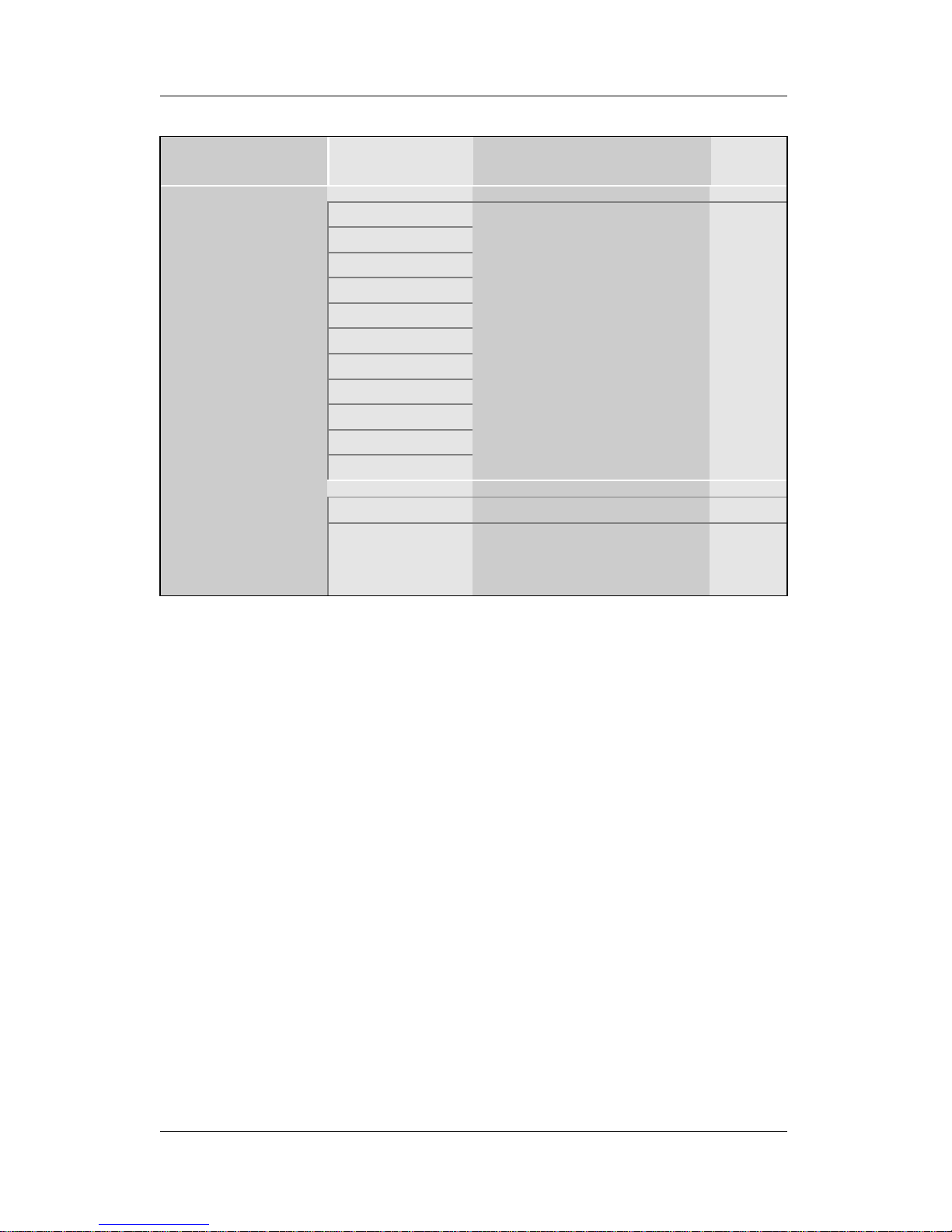
3-1.2 System Boot Control Settings
System Boot
Control Settings
Setting Description Note
A,C,SCSI
C,A,SCSI
C,CD-ROM,A
CD-ROM,C,A
D,A,SCSI
E,A,SCSI
F,A,SCSI
SCSI,A,C
SCSI,C,A
C only
Boot Sequence
LS/ZIP,C
Choose the boot
sequence adapted to
your needs, for example:
l [A,C,SCSI] means
the BIOS will look for an
operating system first in
drive A, then in drive C,
and eventually in SCSI
device.
Disabled
Quick Power On
Self Test
Enabled Provides a fast POST
(Power-On Self Test) at
boot-up.
Default
Page 42
BIOS Setup Utility SY-D6IGA
38
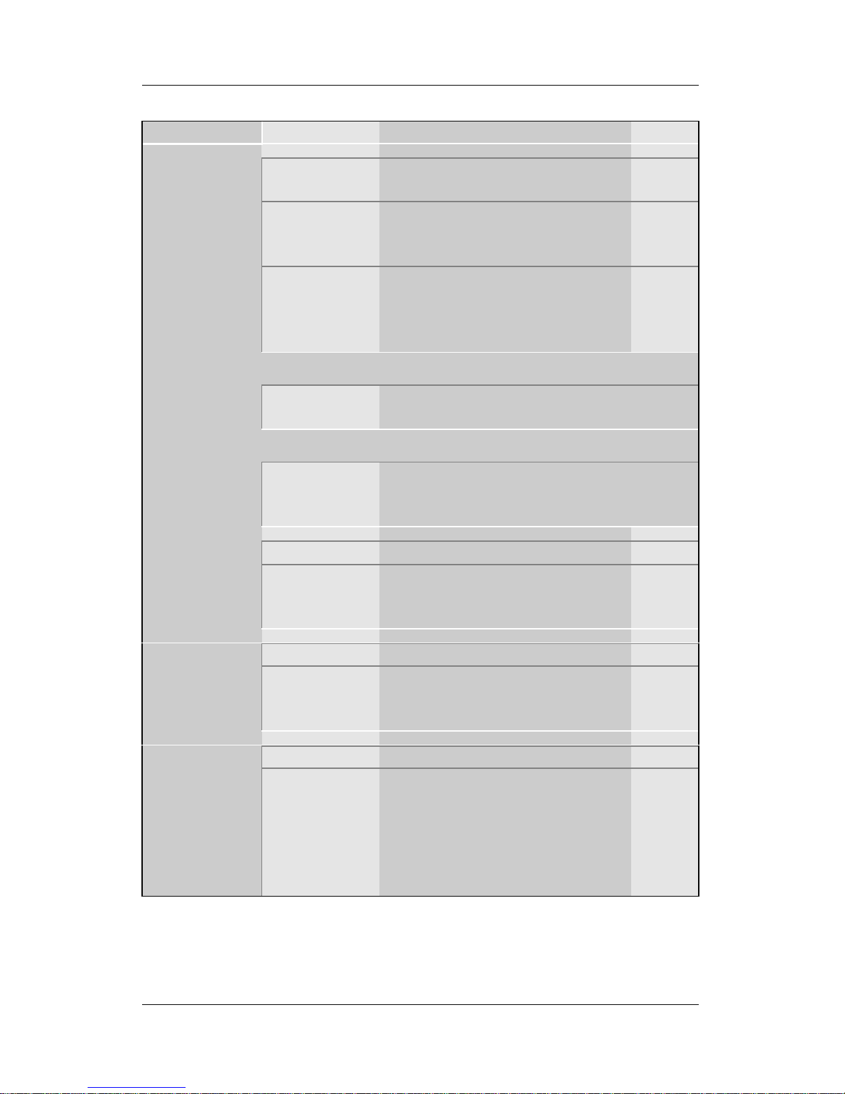
3-1.3 Power Management
PM Events Setting Description Note
BUTTON-ONLY Disables the Wake-Up by
Keyboard function.
Default
KB Power ON
Password
Enables you to wake-up the
system by entering a
password at the keyboard.
POWER ON
Function
Hot Key You can wake-up the system
by pressing the key
combination of your choice
(Ctrl-F1~F12).
If [POWER ON Function] is set to [KB Power ON Password]
KB Power ON
Password
Enter (your
password)
Set the password that will wake-up
your system.
If [POWER ON Function] is set to [Hot Key]
KB Power ON
Password
Ctrl-F1~F12 Choose the key combination that will
wake-up the system.
[Ctrl-F1 to Ctrl-F12]
Instant-off Default
Soft-Off by
PWR-BTTN
Delay 4 Sec. Turns off the system power 4
seconds after pushing the
power button.
Disabled
Power-On by
Ring/LAN
Enabled The system will self-power on
me when the modem is
ringing.
Default
Disabled The system ignores the alarm. Default
Power-On by
Alarm
Enabled Set alarm to power on the
system by the date (1-31) or
time (hh:mm:ss). If the date is
set to [0], the system will selfpower on by alarm everyday
at the set time.
Page 43
BIOS Setup Utility SY-D6IGA
39
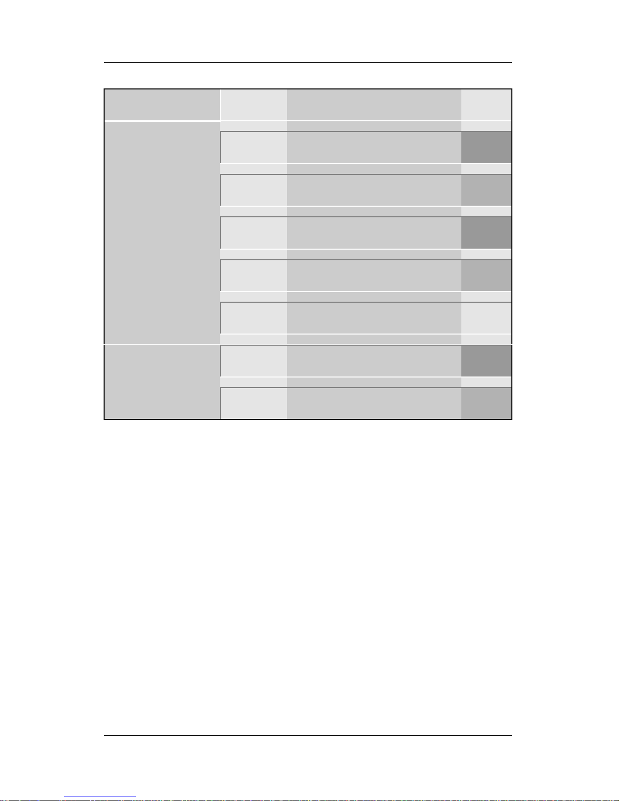
3-1.4 CPU Device Monitoring
CPU Device
Monitoring
Setting Description Note
Current CPU1
Temperature
°C/°F
Shows the current status of
the CPU1 temperature.
Slot2
#1
Current CPU2
Temperature
°C/°F
Shows the current status of
the CPU2 temperature.
Slot2
#2
Current
CPUFAN1 Speed
°C/°F
Shows the current status of
CPU Fan speed for CPU1.
Slot2
#1
Current
CPUFAN2 Speed
°C/°F
Shows the current status of
CPU Fan speed for CPU2.
Slot2
#2
Current
CPUFAN3 Speed
°C/°F
Shows the current status of
the Chassis Fan speed
CPU1(V),
+3.3V, +12V, -5V
V
Shows the current voltage
status on CPU1.
Slot2
#1
CPU2(V),
+5V, -12V
V
Shows the current voltage
status on CPU2.
Slot2
#2
Page 44
BIOS Setup Utility SY-D6IGA
40
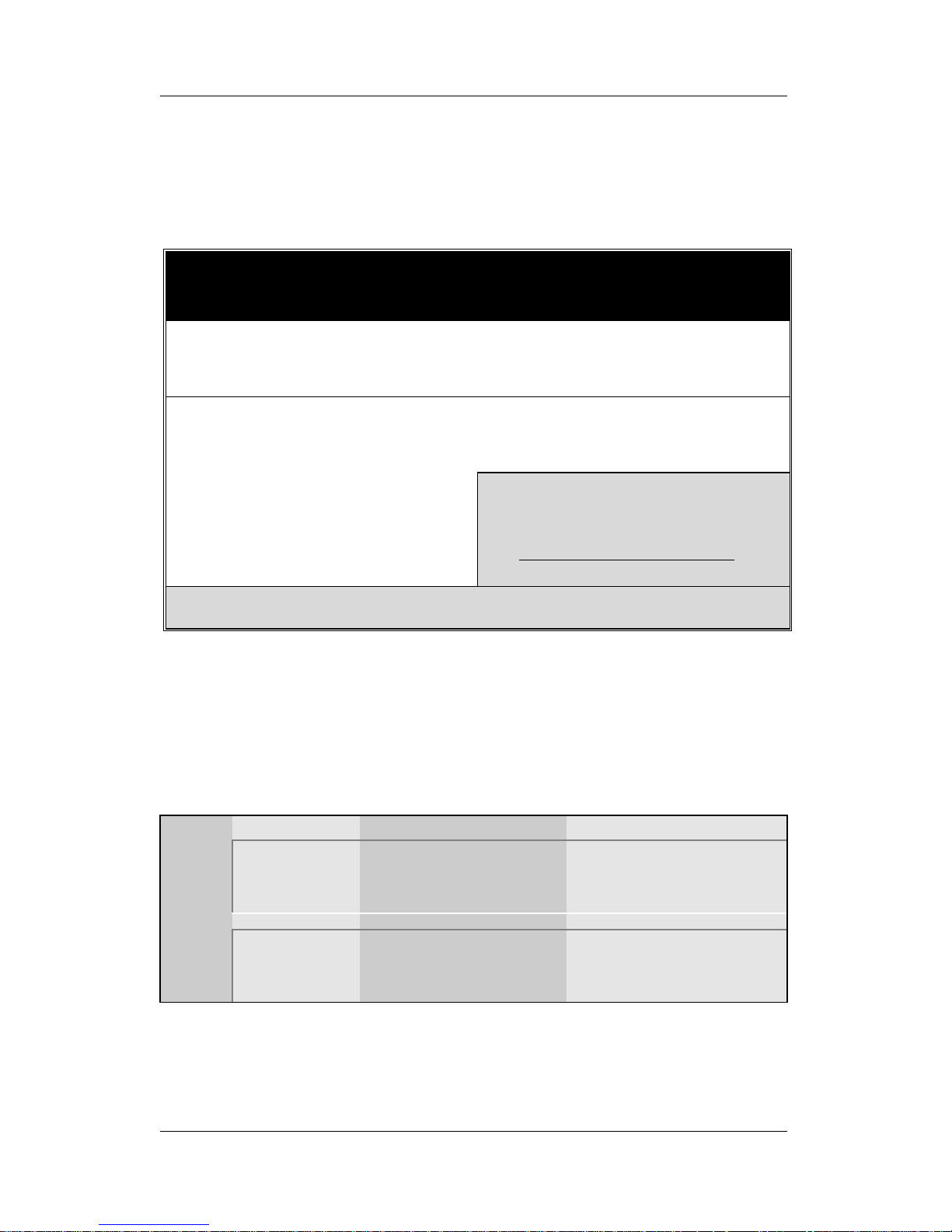
3-2 STANDARD CMOS SETUP
Select the [STANDARD CMOS SETUP] option from the Main Menu
and press [Enter] key.
This screen allows you to modify the basic CMOS settings.
After you have completed the changes, press [Esc] key to return to
the Main Menu.
3-2.1 Date & Time
Display Setting Please Note
Date
mm/dd/yyyy Type the current date You can also press the
PUp/PDn keys to
toggle between values.
Time
hh:mm:ss Type the current time 24-hour clock format
3:15 PM is displayed
as 15:15:00
ROM PCI/ISA BIOS
STANDARD CMOS SETUP
AWARD SOFTWARE, INC.
Date (mm:dd:yy)
Time (hh:mm:ss)
: Mon, Feb 22 1999
: 11 : 30 : 33
HARD DISKS TYPE
SIZE
CYLS
HEAD
PRECOMP
LANDZ
SECTOR
MODE
Primary Master
Primary Slave
Secondary Master
Secondary Slave
: AUTO
: None
: None
: None
00000000000000000000000
0
AUTO
- - - -
- - - -
- - - -
Base Memory:
Extended Memory:
Other Memory:
640K
31744K
384K
Drive A : 1.44M, 3.5 in.
Drive B : None
Floppy 3 Mode Support : Disabled
Video : EGA/VGA
Halt On : All Errors
Total Memory:
32768K
Esc
F1
: Quit
: Help
↑ ↓ → ←
(Shift) F2
: Select Item
: Change Color
PU/PD/+/-F3: Modify
: Toggle Calendar
Page 45
BIOS Setup Utility SY-D6IGA
41
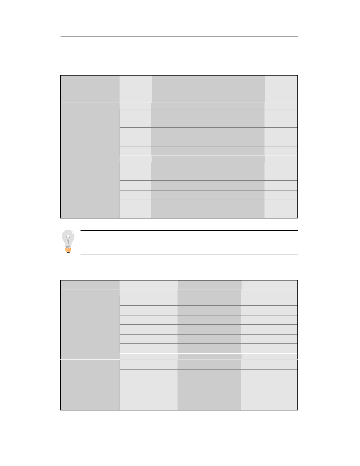
3-2.2 Hard Disks Type & Mode
Choose the type and mode for the hard disks that you have already
installed.
Primary
(Secondary)
Master & Slave
Setting Description Note
Auto BIOS detects hard disk type
automatically.
Default
User User defines the type of hard
disk.
Type
None
Auto BIOS detects hard disk mode
automatically.
Default
Normal Normal IDE hard disk <528MB
LBA Enhanced IDE hard disk >528MB
Mode
Large Large IDE hard disk (for certain
hard disk)
Note: If you have any questions on your hard disk type or
mode, ask your hard disk provider or previous user for details.
3-2.3 Floppy Drives
Floppy Drives Setting Description Note
360KB, 5.25 in.
1.2MB, 5.25 in.
720KB, 3.5 in.
1.44MB, 3.5 in. Default
2.88MB, 3.5 in.
Drives A & B
None Not installed
Disabled Default
Floppy 3-Mode
Support
Drive A
Drive B
Both
Supports 3-mode
floppy diskette:
740KB/1.2MB/
1.44MB on
selected disk drive.
Special disk
drive commonly
used in Japan
Page 46

BIOS Setup Utility SY-D6IGA
42
3-2.4 Video
Select the video mode: EGA/VGA (Default), CGA 40, CGA 80,
MONO (Monochrome).
3-2.5 Halt On
When the BIOS detects system errors, this function will stop the
system. Select which type of error will cause the system halt: All
Errors (Default), No Errors, All But Keyboard, All But Diskette, All
But Disk/Key.
Page 47
BIOS Setup Utility SY-D6IGA
43
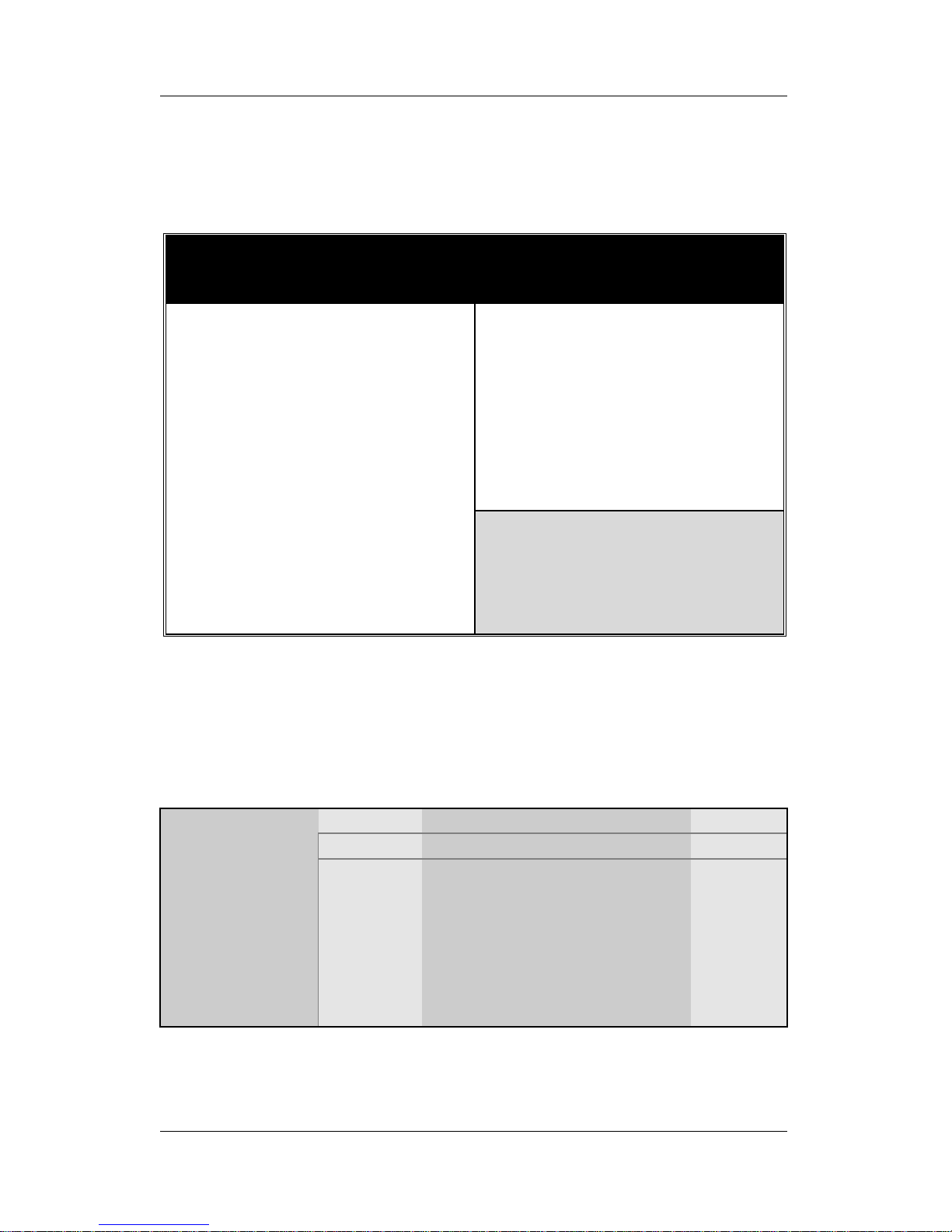
3-3 BIOS FEATURES SETUP
Select the [BIOS FEATURES SETUP] option from the Main Menu
and press [Enter] key.
After you have completed the changes, press [Esc] key and follow
the instructions on your screen to save your settings or exit without
saving.
3-3.1 Virus Warning
Setting Description Note
Disabled Default
Virus Warning
Enabled Enable this option to protect
the boot sectors and
partition tables of your hard
disk. Any attempt to write to
them will the system to halt
and display a warning
message.
ROM PCI/ISA BIOS
BIOS FEATURES SETUP
AWARD SOFTWARE, INC.
Video BIOS Shadow
C8000-CBFFF Shadow
CC000-CFFFF Shadow
D0000-D3FFF Shadow
D4000-D7FFF Shadow
D8000-DBFFF Shadow
DC000-DFFFF Shadow
: Enabled
: Disabled
: Disabled
: Disabled
: Disabled
: Disabled
: Disabled
ESC
F1
F5
: Quit
: Help
: Old Values
PU/PD/+/-
(Shift) F2
: Select Item
: Modify
: Color
Virus Warning
CPU Internal Cache
External Cache
Processor Number Feature
Swap Floppy Drive
Boot Up NumLock Status
Typematic Rate Setting
Typematic Rate (Chars/Sec)
Typematic Delay (Msec)
Security Option
PCI/VGA Palette Snoop
Assign IRQ for VGA
MPS Version Control For OS
OS Select for DRAM > 64MB
HDD S.M.A.R.T. capability
Report No FDD For WIN 95
: Disabled
: Enabled
: Enabled
: Disabled
: Disabled
: On
: Disabled
: 6
: 250
: Setup
: Disabled
: Enabled
: 1.4
: Non-OS2
: Disabled
: Yes
F6F7: Load BIOS Defaults
: Load Setup Defaults
Page 48
BIOS Setup Utility SY-D6IGA
44
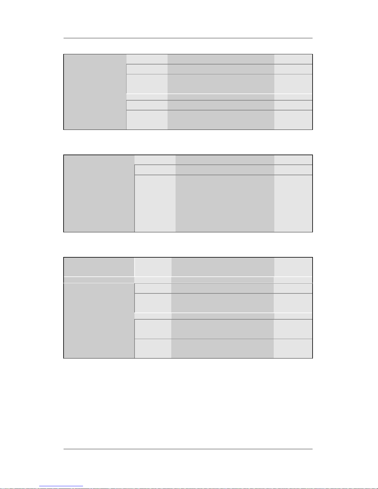
3-3.2 Cache Memory Options
Setting Description Note
Disabled
CPU Internal
Cache
Enabled Enables the CPU's internal
cache.
Default
Disabled
External Cache
Enabled Enables the external
memory.
Default
3-3.3 Processor Number Feature
Setting Description Note
Disabled Default
Processor
Number Feature
Enabled This function enables
your motherboard to
automatically read and
display the Specification
Number of your Pentium
®
III CPU.
3-3.4 System Boot Control Settings
System Boot
Control Settings
Setting Description Note
Disabled Default
Swap Floppy
Drive
Enabled Changes the sequence of
A and B drives.
On Puts numeric keypad in
NumLock mode at boot-up.
Default
Boot Up
NumLock Status
Off Puts numeric keypad in
arrow key mode at boot-up.
Page 49
BIOS Setup Utility SY-D6IGA
45
3-3.5 Typematic Settings
Typematic
Settings
Setting Description Note
Disabled Default
Typematic
Rate Setting
Enabled Enables to adjust the
keystroke repeat rate.
The following [Typematic Rate] and [Typematic Delay] fields are
active only if [Typematic Rate Setting] is set to [Enabled]
Typematic Rate
6 (Char/sec)
8 (Char/sec)
10 (Char/sec)
12 (Char/sec)
15 (Char/sec)
20 (Char/sec)
24 (Char/sec)
30 (Char/sec)
Choose the rate at which
a character is repeated
when holding down a
key.
Default
Typematic Delay
250 (msec)
500 (msec)
750 (msec)
1000 (msec)
Choose how long after
you press a key down the
character begins
repeating.
Default
3-3.6 Security Option
Use this feature to prevent unauthorized system boot-up or use of
BIOS Setup. The following table describes the security settings.
Setting Description Note
System Each time the system is
booted, the password prompt
appears.
Security Option
Setup If a password is set, the
password prompt only appears
when you attempt to enter the
BIOS Setup program.
Default
Page 50
BIOS Setup Utility SY-D6IGA
46
3-3.7 Other Control Options
Other Control
Options
Setting Description Note
Disabled Default
Enabled
PCI/VGA
Palette Snoop
The color of the monitor may be altered
when using an MPEG card. Enable this
option to restore the monitor's normal
color.
Disabled
Assign IRQ
For VGA
Enabled Use this default setting. Default
1.1
MPS Version
Control For OS
1.4
To specify which MPS version
to use.
Default
OS2 When using an OS2 operating
system.
OS Select for
DRAM>64MB
Non-OS2 When using another,
non-OS2 operating system.
Default
Disabled Default
HDD
S.M.A.R.T.
capability
Enabled Enable this field when your
HDD supports the S.M.A.R.T.
function.
Consult your HDD provider for
details.
Yes Windows will release IRQ line
6 (normally used by the
Floppy Disk Drive) after you
disable your on-board FDD
and set this field to [Yes].
Default
Report No FDD
For WIN 95
No Windows will reserve INT 6 for
your FDD, whether it is
disabled or not.
Page 51

BIOS Setup Utility SY-D6IGA
47
Other Control Options (continued)
Other Control
Options
Setting Description Note
Disabled
Enabled
Video
BIOS Shadow
The BIOS is shadowed in a 16K segment
if it is enabled and if it has BIOS present.
These 16 segments can be shadowed
from ROM to RAM. BIOS shadow copies
BIOS code from slower ROM to faster
RAM. BIOS can then execute from RAM.
Default
Disabled Default
C8000-CBFFF/
CC000-CFFFF/
D0000-D3FFF/
D4000-D7FFF/
D8000-DBFFF/
DC000-DFFFF/
Shadow
Enabled The ROM data at the specified
address range will be copied
to RAM.
Page 52
BIOS Setup Utility SY-D6IGA
48
3-4 CHIPSET FEATURES SETUP
Caution: Change these settings only if you are already
familiar with the Chipset.
The [CHIPSET FEATURES SETUP] option changes the values of
the chipset registers. These registers control the system options in
the computer.
After you have completed the changes, press [Esc] and follow the
instructions on your screen to save your settings or exit without
saving.
The following table describes each field in the CHIPSET
FEATURES SETUP Menu and how to configure each parameter.
ROM PCI/ISA BIOS
CHIPSET FEATURES SETUP
AWARD SOFTWARE, INC.
ESC
F1
F5
: Quit
: Help
: Old Values
PU/PD/+/-
(Shift) F2
: Select Item
: Modify
: Color
SDRAM CAS latency Time
DRAM Data Integrity Mode
System BIOS Cacheable
Video BIOS Cacheable
Video RAM Cacheable
8 Bit I/O Recovery Time
16 Bit I/O Recovery Time
Memory Hole At 15M-16M
Passive Release
Delayed Transaction
AGP Aperture Size (MB)
Spread Spectrum Modulated
: 3
: Non-ECC
: Disabled
: Disabled
: Disabled
: 1
: 1
: Disabled
: Enabled
: Enabled
: 64
: Disabled
F6F7: Load BIOS Defaults
: Load Setup Defaults
Page 53
BIOS Setup Utility SY-D6IGA
49
CHIPSET FEATURES SETUP
CHIPSET
FEATURES
Setting Description Note
SDRAM Cache
Latency Time
3
2
Use the default setting Default
Non-ECC Default
DRAM Data
Integrity Mode
ECC
Choose according to the
DRAM type you have.
Disabled Default
System BIOS
Cacheable
Enabled The ROM area F0000H-
FFFFFH is cacheable.
Disabled Default
Video BIOS
Cacheable
Enabled The video BIOS C0000H-
C7FFFH is cacheable.
Disabled Default
Video RAM
Cacheable
Enabled The ROM area A0000-
BFFFF is cacheable.
8 BIT I/O
Recovery Time
1
2-8,NA
Use the default setting Default
16 BIT I/O
Recovery Time
1
2-4,NA
Use the default setting Default
Disabled Default
Memory Hole At
15M-16M
Enabled Some interface cards will
map their ROM address to
this area. If this occurs,
select [Enabled] in this field.
Page 54

BIOS Setup Utility SY-D6IGA
50
CHIPSET FEATURES SETUP (Continued)
CHIPSET
FEATURES
Setting Description Note
Passive Release
Enabled Use the default setting Default
Delayed
Transaction
Enabled Use the default setting Default
AGP Aperture
Size
64
4-256MB
AGP could use the DRAM
as its video RAM. Choose
the DRAM size that you
wish to allocate as video
RAM.
Default
Disabled Default
Spread Spectrum
Modulated
Enabled When using Spread
Spectrum modulated 1.5%
or 6% for FCC or DOC
testing.
Page 55
BIOS Setup Utility SY-D6IGA
51
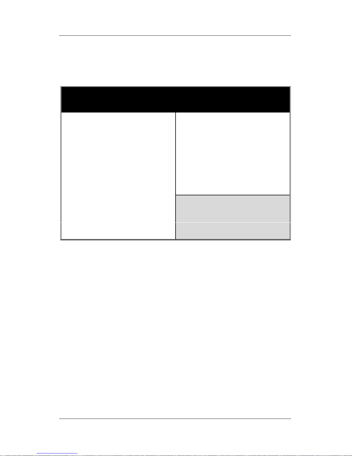
3-5 POWER MANAGEMENT SETUP
The [POWER MANAGEMENT SETUP] sets the system's power
saving functions.
After you have completed the Power Management Setup, press
[Esc] to return to the Main Menu.
ROM PCI/ISA BIOS
POWER MANAGEMENT SETUP
AWARD SOFTWARE, INC.
** Reload Global Timer Events **
IRQ [3-7,9-15], NMI
Primary IDE 0
Primary IDE 1
Secondary IDE 0
Secondary IDE 1
Floppy Disk
Serial Port
Parallel Port
: Enabled
: Disabled
: Disabled
: Disabled
: Disabled
: Disabled
: Enabled
: Disabled
ESC
F1
F5
: Quit
: Help
: Old Values
PU/PD/+/-
(Shift) F2
: Select Item
: Modify
: Color
Power Management
PM Control by APM
Video Off Method
Video Off After
MODEM Use IRQ
Doze Mode
Standby Mode
Suspend Mode
HDD Power Down
PCI/VGA Act-Monitor
CPUFAN Off In Suspend
IRQ 8 Break Suspend
: User Define
: Yes
: V/H SYNC+Blank
: Standby
: 3
: Disable
: Disable
: Disable
: Disable
: Disabled
: Enabled
: Disabled
F6F7: Load BIOS Defaults
: Load Setup Defaults
Page 56
BIOS Setup Utility SY-D6IGA
52
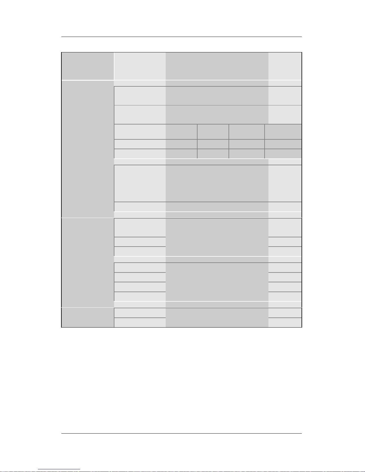
3-5.1 Power Management Controls
Power
Management
Controls
Setting Description Note
User Define Lets you define the HDD and
system power down times.
Default
Disable Disables the Green PC
Features.
Doze
timer
Standby
timer
Suspend
timer
HDD
power down
Min Saving 1 Hour 1 Hour 1 Hour 15 Min
Power
Management
Max Saving 1 Min 1 Min 1 Min 1 Min
Yes To use Advanced Power
Management (APM) you
must run [power.exe] under
DOS V6.0 or later version.
Default
PM Control
by APM
No
V/H
Sync+Blank
Default
Blank Screen
Video Off
Method
DPMS
Selects the method by which
the monitor is blanked.
Standby Default
Suspend
Doze
Video Off
After
NA
Choose the PM mode you
want video to go off after the
mode is being active.
3 Default
MODEM Use
IRQ
3-11,NA
Assigns an IRQ# to the
modem device.
Page 57
BIOS Setup Utility SY-D6IGA
53
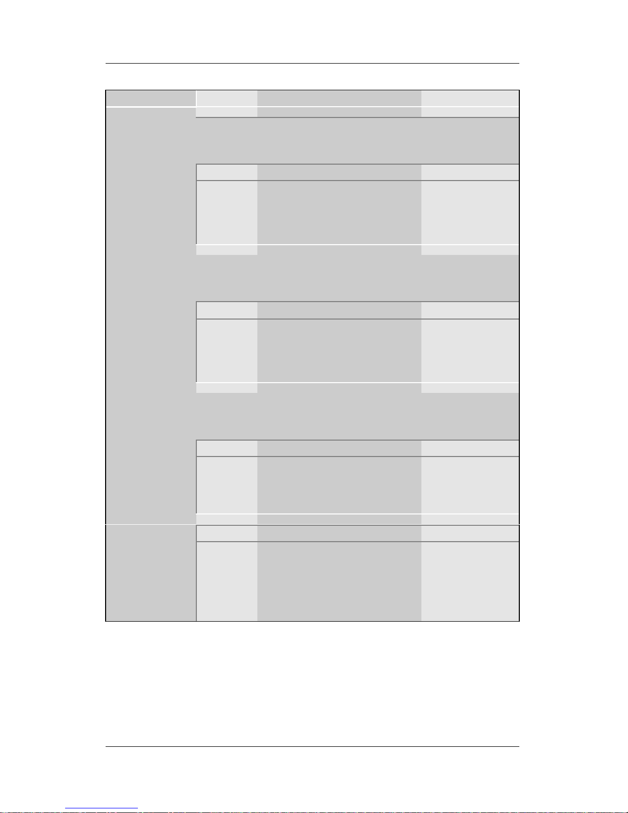
3-5.2 PM Timers
PM Timers Setting Description Note
The following [Doze Mode] field may be configured only if [Power
Management] is set to [User Define]
Disable Default
Doze Mode
1Min1Hour
When the set time has
elapsed, BIOS sends a
command to the system to
enter Doze Mode.
System clock
drops to
33MHz.
The following [Standby Mode] field may be configured only if [Power
Management] is set to [User Define]
Disable Default
Standby
Mode
1Min1Hour
When the set time has
elapsed, BIOS sends a
command to the system to
enter Standby Mode.
The following [Suspend Mode] field may be configured only if
[Power Management] is set to [User Define]
Disable Default
Suspend
Mode
1Min1Hour
In Suspend mode, the
CPU stops completely (no
instructions are executed.)
Only an SLEnhanced (or
SMI) CPU can
enter this mode.
Disabled Default
HDD Power
Down
1-15Min When the set time has
elapsed, BIOS sends a
command to the HDD to
power down. This turns off
the HDD motor.
Some older
model HDDs
may not support
this advanced
function.
Page 58
BIOS Setup Utility SY-D6IGA
54
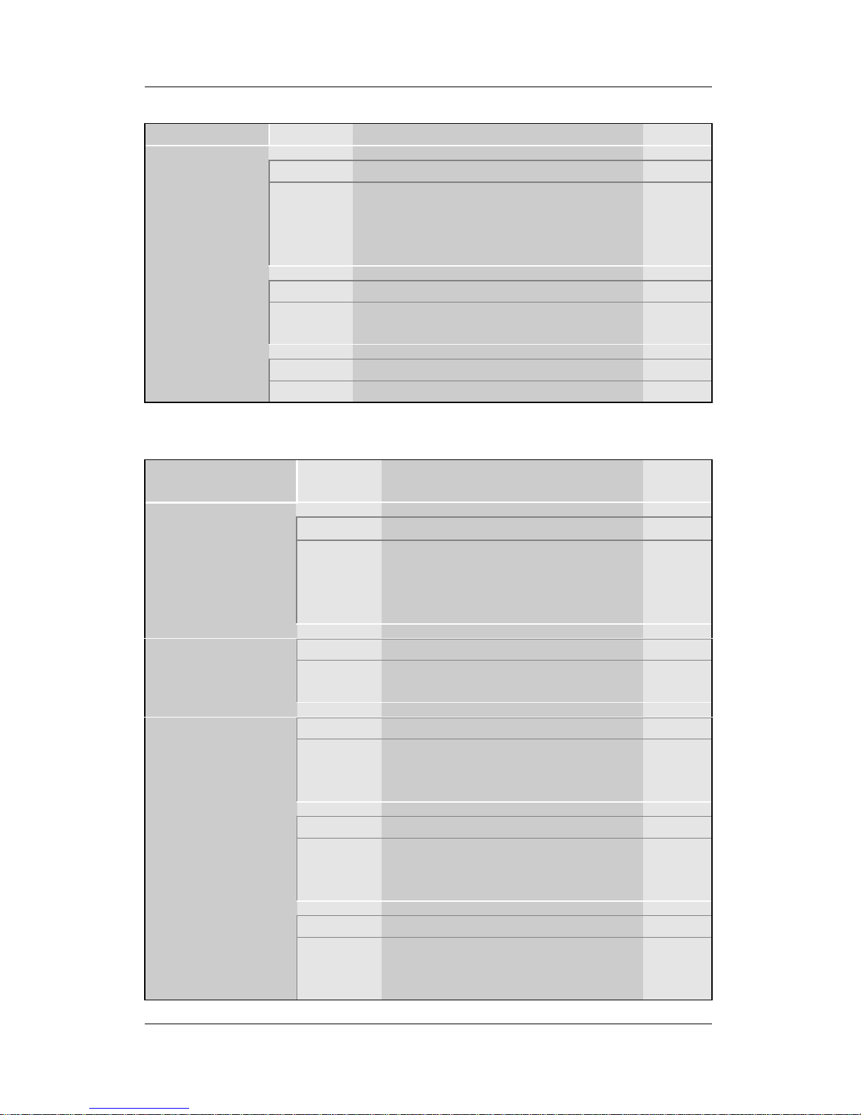
3-5.3 PM Events
PM Events Setting Description Note
Disabled DefaultPCI/VGA
Act-Monitor
Enabled Enables the power management
timers when a [no activity] event is
detected on the PCI device and
monitor.
Disabled Disables the PM timer.CPUFAN Off
In Suspend
Enabled Switches off the CPU Fan when
the system enters Suspend Mode.
Default
Disabled DefaultIRQ 8 Break
Suspend
Enabled Alarm function is active.
3-5.4 Reload Global Timer Events
Power Down &
Resume Events
Setting Description Note
DisabledIRQ [3-7,9-15],
NMI
Enabled The system monitors these
elements for activity. The
system will resume if an [IRQ
activity] is detected.
Default
Disabled DefaultIDE0, IDE1
Ø Primary
Ø Secondary
Enabled Enables the PM timers when
[No Activity Event] is detected.
Disabled DefaultFloppy Disk
Enabled Enables the PM timers when
[No Activity Event] is detected
on the floppy disk drive.
DisabledSerial Port
Enabled Enables the PM timers when
[No Activity Event] is detected
on the serial port.
Default
Disabled DefaultParallel Port
Enabled Enables the PM timers when
[No Activity Event] is detected
on the parallel port.
Page 59
BIOS Setup Utility SY-D6IGA
55
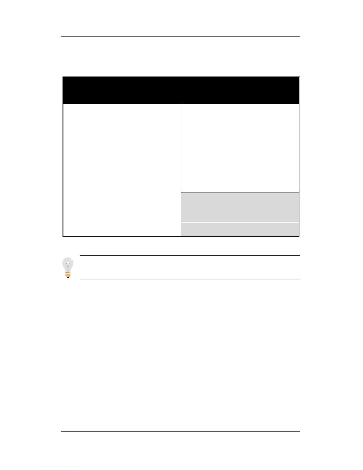
3-6 PNP/PCI CONFIGURATION SETUP
This option sets the motherboard's PCI Slots.
Note: Starred (*) items will disappear when the [Resources
Controlled By] option is set to [Auto].
After you have completed the PCI Slot Configuration, press [Esc]
and follow the instructions on your screen to save your settings or
exit without saving.
ROM PCI/ISA BIOS
PNP/PCI CONFIGURATION
AWARD SOFTWARE, INC.
PnP OS Installed
Resources Controlled By
Reset Configuration Data
: No
: Manual
: Disabled
Used MEM base addr
Assign IRQ For USB
: N/A
: Enabled
ESC
F1
F5
: Quit
: Help
: Old Values
↑ ↓ → ←
PU/PD/+/ (Shift) F2
: Select Item
: Modify
: Color
IRQ-3
IRQ-4
IRQ-5
IRQ-7
IRQ-9
IRQ-10
IRQ-11
IRQ-12
IRQ-14
IRQ-15
DMA-0
DMA-1
DMA-3
DMA-5
DMA-6
DMA-7
assigned to
assigned to
assigned to
assigned to
assigned to
assigned to
assigned to
assigned to
assigned to
assigned to
assigned to
assigned to
assigned to
assigned to
assigned to
assigned to
: Legacy ISA*
: Legacy ISA*
: PCI/ISA PnP*
: PCI/ISA PnP*
: PCI/ISA PnP*
: PCI/ISA PnP*
: PCI/ISA PnP*
: PCI/ISA PnP*
: PCI/ISA PnP*
: PCI/ISA PnP*
: PCI/ISA PnP*
: PCI/ISA PnP*
: PCI/ISA PnP*
: PCI/ISA PnP*
: PCI/ISA PnP*
: PCI/ISA PnP*
F6F7: Load BIOS Defaults
: Load Setup Defaults
Page 60
BIOS Setup Utility SY-D6IGA
56
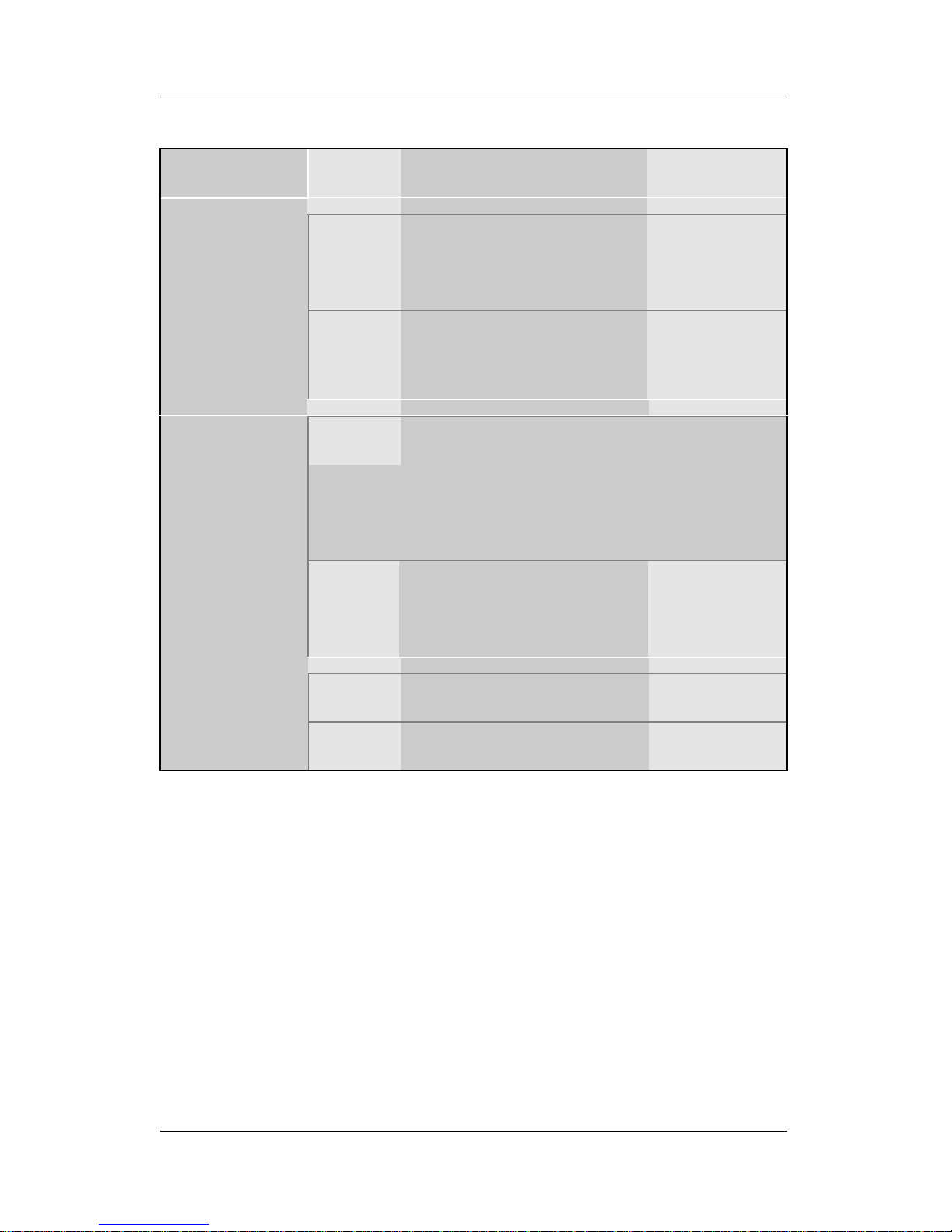
3-6.1 PNP/PCI Configuration Controls
PNP/PCI
Controls
Setting Description Note
Yes Set this field to [Yes] if you
are running Windows
95/98, which are PnP
compatible.
PnP OS
Installed
No If the OS you are running
does not support PnP
configuration.
Default
(If there is any
doubt, set this
field to [No])
Manual BIOS does not manage PCI/ISA
PnP card IRQ assignment.
Requires to assign IRQ-# and DMA-# to PCI
or ISA PnP manually.
IRQ-3,4,5,7,9,10,11,12,14,15 assigned to: _
DMA-0,1,3,5,6,7 assigned to: _
Resources
Controlled By
Auto The Plug-and-Play BIOS
auto manages PCI/ISA
PnP card IRQ assignment
automatically.
Recommended
Disabled Retain PnP configuration
data in BIOS.
Default
Reset
Configuration
Data
Enabled Reset PnP configuration
data in BIOS.
Page 61
BIOS Setup Utility SY-D6IGA
57
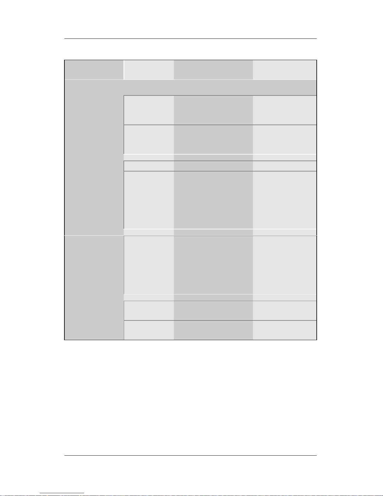
3-6.2 PNP/PCI Configuration Setup
PNP/PCI
Setup
Setting Description Note
If [Resources Controlled By] is set to [Manual]
PCI/ISA PnP Choose IRQ-# and
DMA-# assigned to
PCI/ISA PnP card.
IRQ-3,4,5,7,9,10,
11,12,14,15
DMA-0,1,3,5,6,7
IRQ-# and
DMA-#
assigned to:
Legacy ISA Choose IRQ-# and
DMA-# assigned to
Legacy ISA card.
IRQ-3,4,5,7,9,10,
11,12,14,15
DMA-0,1,3,5,6,7
N/A Default
Used MEM
base addr
I/O address C800,CC00,D000,D
400,D800,DC00.
(Asking card
provider for the
exactly I/O address
of this add-on card.)
Use this function
only when
problems occur
while using
some certain
add-on cards.
Used MEM
Length
Memory
length
8K,16K,32K,64K.
(Please ask your
card provider for the
exactly memory
length of this add-on
card.)
This item
appears only
when the [Used
MEM base addr]
field is set to I/O
address.
Enabled BIOS will assign IRQ
for USB port.
Default
Assign IRQ
For USB
Disabled BIOS won’ t assign
IRQ for USB port.
Page 62
BIOS Setup Utility SY-D6IGA
58
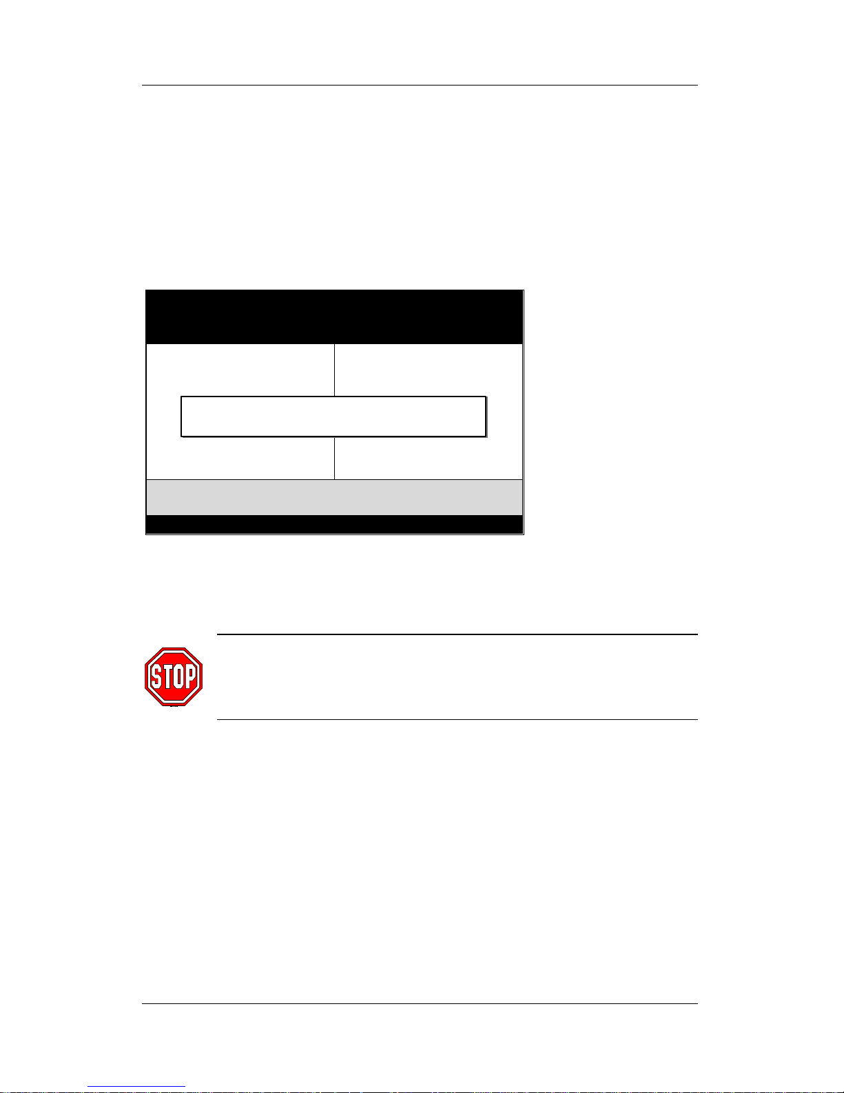
3-7 LOAD SETUP DEFAULTS
Select the [LOAD SETUP DEFAULTS] option from the Main Menu to
load the system values you have previously saved. This option is
recommended if you need to reset the system setup and to retrieve
the old values.
Type [Y] to use the Setup Defaults followed by [Enter] or otherwise
[N] to return to the Main Menu and keep current values.
Warning: If you run into any problem after changing the
BIOS configuration, please load the SETUP DEFAULTS for
stable performance.
ROM PCI/ISA BIOS
CMOS SETUP UTILITY
AWARD SOFTWARE, INC.
SOYO COMBO SETUP
STANDARD CMOS SETUP
BIOS FEATURES SETUP
CHIPSET FEATURES SETUP
POWER MANAGEMENT SETUP
PNP/PCI CONFIGURATION
LOAD SETUP DEFAULTS
INTEGRATED PERIPHERALS
SUPERVISOR PASSWORD
USER PASSWORD
IDE HDD AUTO DETECTION
SAVE & EXIT SETUP
EXIT WITHOUT SAVING
Esc
F10
: Quit
: Save & Exit Setup
↑ ↓ → ←
(Shift) F2
: Select Item
: Change Color
Time, Date, Hard Disk Type…
Load SETUP Defaults (Y/N)? _
Page 63
BIOS Setup Utility SY-D6IGA
59
3-8 INTEGRATED PERIPHERALS
Caution: Change these settings only if you are already
familiar with the Chipset.
The [INTEGRATED PERIPHERALS] option changes the values of
the chipset registers. These registers control the system options in
the computer.
The following screen shows setup default settings.
The following tables describe each field in the INTEGRATED
PERIPHERALS Menu and provide instructions on how to configure
the IDE controls, FDC controls, and the onboard serial and parallel
ports.
ROM PCI/ISA BIOS
INTEGRATED PERIPHERALS
AWARD SOFTWARE, INC.
Onboard FDC Controller
Onboard Serial Port 1
Onboard Serial Port 2
URART Mode Select
RxD , TxD Active
IR Transmission Delay
Onboard Parallel Port
Parallel Port Mode
ECP Mode Use DMA
EPP Mode Select
: Enabled
: 3F8/IRQ4
: 2F8/IRQ3
: Normal
: Hi,Lo
: Enabled
: 378/IRQ7
: SPP
: 3
: EPP1.7
ESC
F1
F5
: Quit
: Help
: Old Values
PU/PD/+/-
(Shift) F2
: Select Item
: Modify
: Color
IDE HDD Block Mode
IDE Primary Master PIO
IDE Primary Slave PIO
IDE Secondary Master PIO
IDE Secondary Slave PIO
IDE Primary Master UDMA
IDE Primary Slave UDMA
IDE Secondary Master UDMA
IDE Secondary Slave UDMA
On-Chip Primary PCI IDE
On-Chip Secondary PCI IDE
Onboard PCI SCSI Chip
USB Keyboard Support
Init Display First
KBC Input Clock
: Enabled
: Auto
: Auto
: Auto
: Auto
: Auto
: Auto
: Auto
: Auto
: Enabled
: Enabled
: Enabled
: Disabled
: PCI Slot
: 12
F6F7: Load BIOS Defaults
: Load Setup Defaults
Page 64
BIOS Setup Utility SY-D6IGA
60
3-8.1 IDE Device Controls
IDE Controls Setting Description Note
Disabled
IDE HDD Block Mode
Enabled Invokes multi-sector
transfer instead of one
sector per transfer. Not
all HDDs support this
function.
Default
mode 0-4 0 is the slowest speed
4 is the fastest speed
IDE
Ø Primary Master PIO
Ø Primary Slave PIO
Ø Secondary Master PIO
Ø Secondary Slave PIO
Auto For better performance
and stability, we
suggest you use the
Auto setting to set the
HDD control timing.
Default
Disabled
IDE
Ø Primary Master UDMA
Ø Primary Slave UDMA
Ø Secondary Master UDMA
Ø Secondary Slave UDMA
Auto Select Auto to enable
Ultra DMA Mode
support.
Default
Disabled Turn off the on-board
IDE
On-Chip PCI IDE
Ø Primary
Ø Secondary
Enabled Use the on-board IDE Default
3-8.2 Onboard SCSI Subsystem Controls
SCSI Subsystem
Controls
Setting Description Note
Disabled
Onboard PCI SCSI
Chip
Enabled Enables the on-board SCSI
function.
Also, allows you to configure
the SCSISelect™ BIOS
utility. (Press <Ctrl-A> during
boot-up to enter the SCSI
BIOS utility.)
Default
Page 65
BIOS Setup Utility SY-D6IGA
61
3-8.3 USB Keyboard Support
USB Keyboard Setting Description Note
Disabled Default
USB Keyboard
Support
Enabled Use a USB keyboard
3-8.4 Display Controls
Display Controls Setting Description Note
PCI Slot Default
Init Display First
AGP
Choose which card –
AGP Display card or
PCI VGA card – to
initialize first.
3-8.5 Keyboard Controls
Keyboard Controls Setting Description Note
6
8
12 Default
KBC Input Clock
16
Controls the frequency of
the clock signal (MHz) of
the keyboard.
Set this value to 8 (MHz) if
experiencing problems
with your keyboard.
Page 66
BIOS Setup Utility SY-D6IGA
62
3-8.6 FDC Controls
FDC Controls Setting Description Note
Disabled Turn off the on-board
floppy controller
Onboard FDC
controller
Enabled Use the on-board
floppy controller
Default
3-8.7 Onboard Serial Ports
Onboard Serial
Ports
Setting Description Note
Disabled
3F8/IRQ4 Default
(port 1)
2F8/IRQ3 Default
(port 2)
3E8/IRQ4
2E8/IRQ3
Onboard
Ø Serial Port 1
Ø Serial Port 2
Auto
Choose serial port 1 &
2's I/O address.
Do not set port 1 & 2 to
the same address
except for [Disabled] or
[Auto].
Normal Supports a Standard
serial infrared IrDA.
Default
IrDA 1.0
ASKIR Supports a Sharp
serial interface format.
UART Mode Select
FIR Fast Infrared Interface
VxD,TxD Active
Hi,Lo/Lo,Hi/Lo,
Lo/Hi,Hi
Check with your IR-device
provider for exact setting.
Enabled Default
IR Transmission
Delay
Disabled
Check with your IR-device
provider for exact setting.
Page 67
BIOS Setup Utility SY-D6IGA
63
3-8.8 Onboard Parallel Ports
Onboard Parallel
Ports
Setting Description Note
378/IRQ7 Default
3BC/IRQ7
278/IRQ5
Onboard Parallel
Port
Disable
Choose the printer I/O
address.
ECP/EPP
SPP Default
ECP
Parallel Port Mode
EPP
The mode depends on
your external parallel
device that connects to
this port.
If [Parallel Port Mode] is set to [ECP] or [ECP/EPP] mode
3 Choose DMA3 Default
ECP Mode use DMA
1 Choose DMA1
If [Parallel Port Mode] is set to [EPP] or [ECP/EPP] mode
EPP1.7 Default
EPP Mode Select
EPP1.9
Select the correct EPP
operating mode of your
on-board parallel port.
(This setting should
match your parallel
device requirements.)
3-8.9 MULTI I/O ADDRESSES
Default settings for multi-I/O addresses are as follows:
Port I/O Address IRQ Status
LPT1
378 7 SPP
COM1
3F8 4
COM2
2F8 3
Warning: If a default I/O address conflicts with other I/O
cards such as sound card, you must change one of the I/O
addresses to remedy to this address conflict. (I/O addresses
can be adjusted from the BIOS Setup Utility)
Page 68
BIOS Setup Utility SY-D6IGA
64
3-9 SUPERVISOR PASSWORD
Based on the setting you have made in the [Security Option] of the
[BIOS FEATURES SETUP] section, the password prevents access
to the system or the setup program by unauthorized users. Follow
this procedure to set a new password or disable the password:
1. Choose [BIOS FEATURES SETUP] in the Main Menu and
press [Enter]. Select the [Security Options] item and set the
field to:
a. [System]: The password is required every time the system
is booted. This means only a person who knows the
password can use this computer.
b. [Setup]: The password is required only when you attempt
to enter the BIOS Setup program.
2. Choose [SUPERVISOR PASSWORD] from the Main Menu and
press [Enter]. The following prompt appear:
Warning: If you forget or lose the password, the only way
to access the system is to set jumper JP5 to clear the
CMOS RAM. All setup information is lost and you must run
the BIOS setup program again.
Note: If you do not wish to use the password function,
press [Enter] directly and the following message appears:
Enter Password:
Password Disabled!!
Page 69
BIOS Setup Utility SY-D6IGA
65
3. Enter your new password and press [Enter]. The following
message appears, prompting to confirm the new password:
4. Re-enter your password and then press [Enter] to exit to the
Main Menu.
This diagram outlines the password selection procedure:
3-10 USER PASSWORD
When the user password option is on, you are not allowed to change
any setting in the [CMOS SETUP UTILITY] except for changing the
user's password.
The password setting procedure is similar to that for the
[SUPERVISOR PASSWORD] (Refer to section 3-9).
ROM PCI/ISA BIOS
CMOS SETUP UTILITY
AWARD SOFTWARE, INC.
STANDARD CMOS SETUP
BIOS FEATURES SETUP
CHIPSET FEATURES SETUP
POWER MANAGEMENT SETUP
PNP/PCI CONFIGURATION
LOAD SETUP DEFAULTS
LOAD BIOS DEFAULTS
INTEGRATED PERIPHERALS
SUPERVISOR PASSWORD
USER PASSWORD
IDE HDD AUTO DETECTION
SAVE & EXIT SETUP
EXIT WITHOUT SAVING
Esc
F10
: Quit
: Save & Exit Setup
↑ ↓ → ←
(Shift) F2
: Select Item
: Change Color
Time, Date, Hard Disk Type…
Enter Password:
Enter Password:
∗∗∗∗∗
Password Disabled!!
Confirm Password:
∗∗∗∗∗
Press:
↔
Without entering password
Type the Password
Press:
↔
After you confirm the
password, press
°
to exit
Type the Password
and Press: <Enter>
Press <Enter> without
entering the password
After you confirm the password,
press <Esc> to exit
Confirm Password:
Page 70
BIOS Setup Utility SY-D6IGA
66
3-11 IDE HDD AUTO DETECTION
This Main Menu function automatically detects the hard disk type
and configures the STANDARD CMOS SETUP accordingly.
ROM PCI/ISA BIOS
CMOS SETUP UTILITY
AWARD SOFTWARE, INC.
HARD DISKS TYPE SIZE CYLS HEAD PRECOMP LANDZ SECTOR MODE
Primary Master :
Select Primary Master Option (N=Skip) : N
OPTIONS SIZE CYLS HEAD PRECOMP LANDZ SECTOR MODE
2(Y) 1707 827 64 0 3308 63 LBA
1 1707 3309 16 65535 3308 63 NORMAL
3 1707 827 64 65535 3308 63 LARGE
Note: Some Oses( SCO-UNIX Before v5.0) must use “NORMAL” for installation
Note: This function is only valid for IDE type of hard disk drives.
ESC : Skip
Page 71
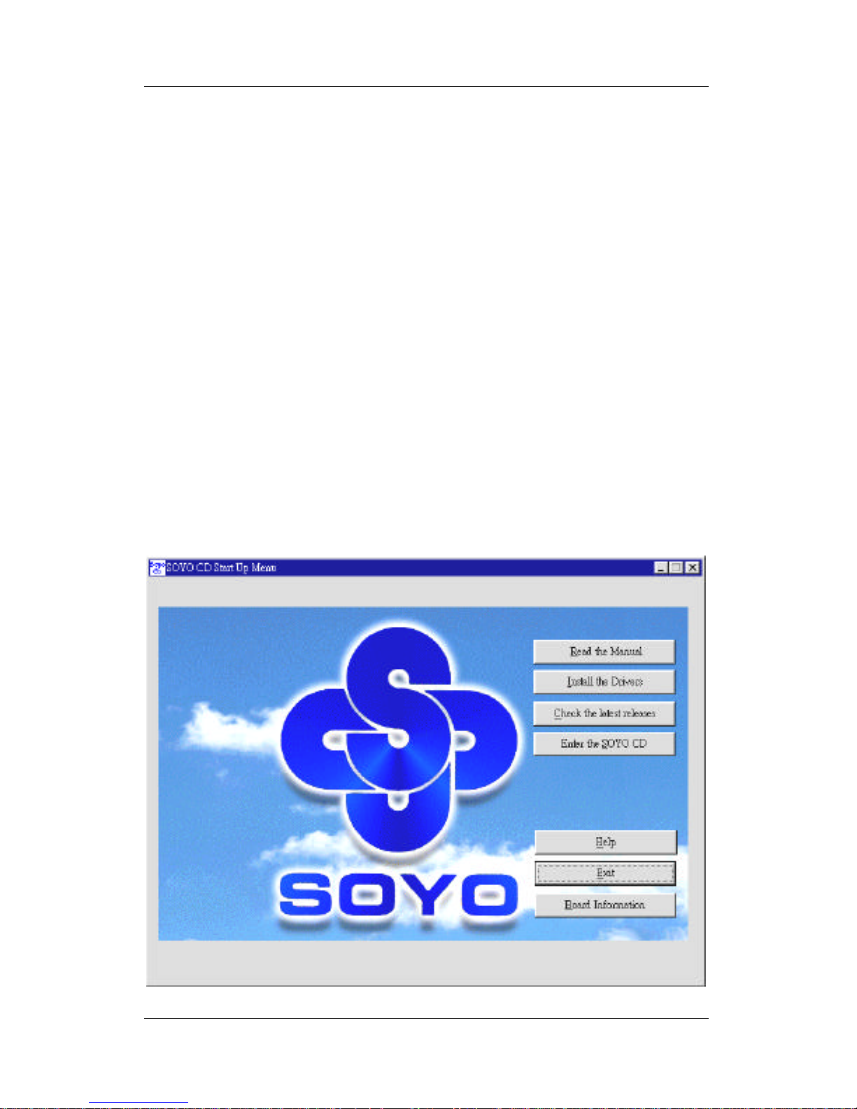
Drivers Installation SY-D6IGA
67
Chapter 4
DRIVERS INSTALLATION
Your SY-D6IGA Motherboard comes with a CD-ROM labeled
"SOYO CD." The SOYO CD contains the user's manual file for your
new motherboard, the drivers software available for installation, and
a database in HTML format with information on SOYO
motherboards and other products.
The SOYO CD Start Up Program automatically detects which SOYO
motherboard you own and displays the corresponding model name.
Step 1. Insert the SOYO CD into the CD-ROM drive
The SOYO CD will auto-run, and the SOYO CD Start Up Menu will
display as shown below.
Page 72
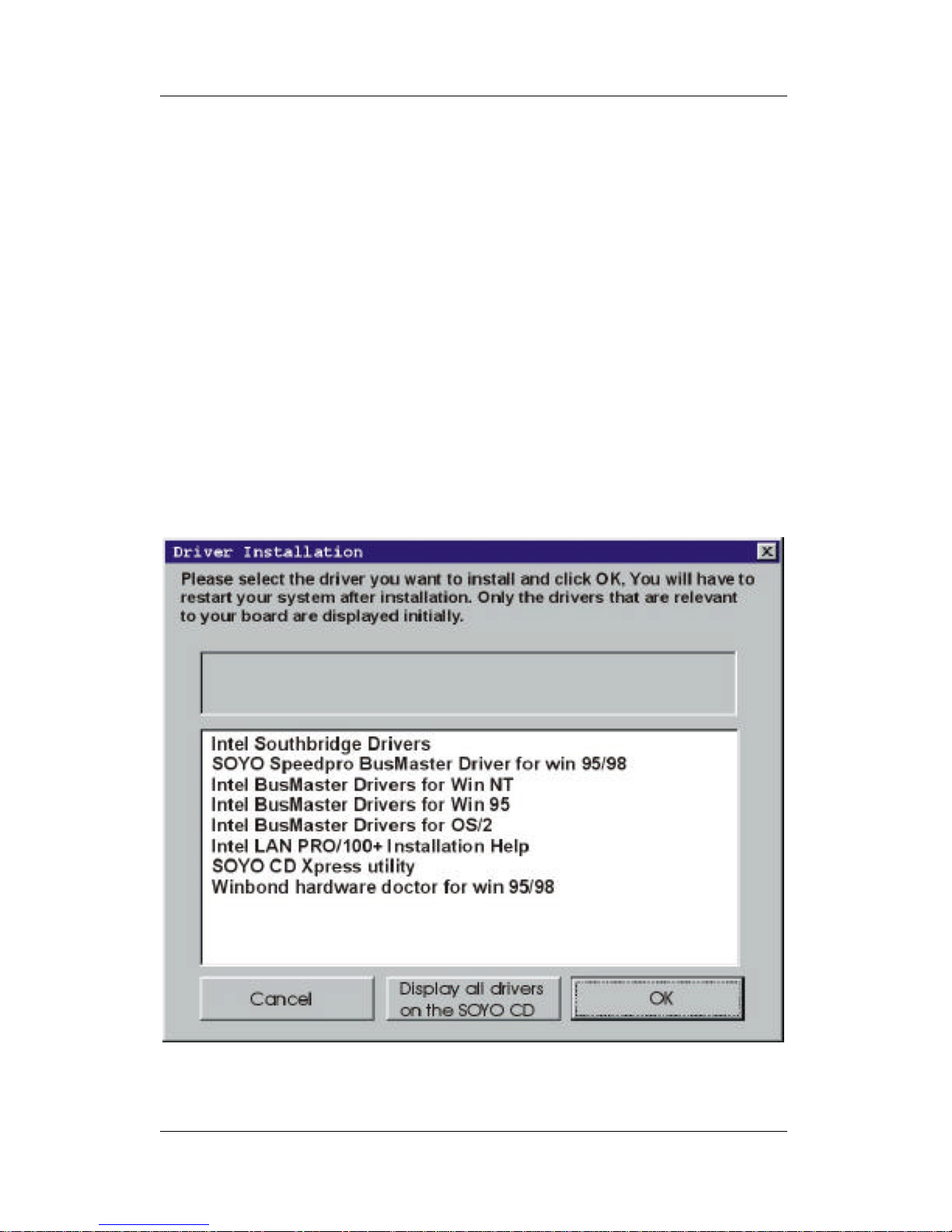
Drivers Installation SY-D6IGA
68
Step 2. Install Drivers
Click the Install Drivers button to display the list of drivers software
that can be installed with your motherboard. The Start Up program
displays the drivers available for the particular model of
motherboard you own. We recommend that you only install those
drivers.
To display the list of all drivers software available with SOYO
motherboards, click the Display all drivers on the SOYO CD button.
Please make sure to install only the drivers adapted to your system,
or otherwise this cause system malfunctions.
The following drivers are available for Windows® 95.
Page 73
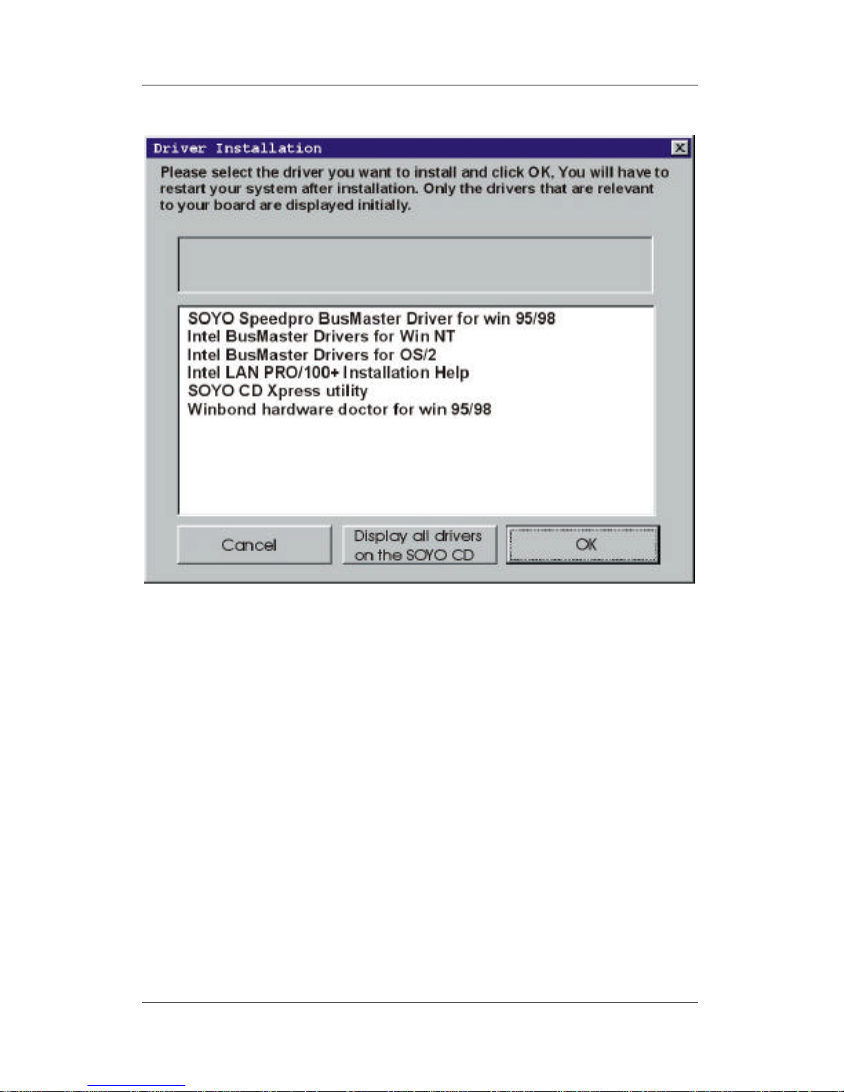
Drivers Installation SY-D6IGA
69
The following drivers are available for Windows® 98.
A short description of all available drivers follows:
Ø Intel Southbridge Drivers
Because Windows 95 does not recognize the Southbridge of the
newer Intel chipsets (TX, BX, ZX etc) this utility has to be run, it will
update the necessary Windows files. (Only for Windows 95)
Ø SOYO SpeedPro Busmaster Driver for Win 95/98
Without the busmaster drivers the CPU will need to be involved
every time data is read from or written to the Harddisk. The
busmaster drivers make use of DMA (Direct Memory Access) to
relieve the CPU of this burden, thus speeding up the system.
The SOYO SpeedPro driver makes use of an advanced caching
algorithm, which gives it an advantage over other busmaster drivers.
Ø Intel Busmaster Drivers for Windows 95
Ø Intel Busmaster Drivers for Win NT
Page 74

Drivers Installation SY-D6IGA
70
Ø Intel Busmaster Drivers for OS/2
These are the official busmaster drivers as supplied by Intel.
Note: Do NEVER install two types of busmaster drivers on
your system, this will lead to conflicts and system instability.
Therefore, if you install the SOYO SpeedPro Busmaster
driver you can NOT install the Intel Busmaster drivers.
Before installing a new busmaster driver first UNINSTALL the
old busmaster driver.
Ø Intel LAN PRO/100+ Installation Help
These are the electronic help files as provided by Intel, for more
information on the installation of the Intel LAN PRO/100+ drivers,
select this item and click ‘ OK’ .
Ø SOYO CD Xpress Utility
This utility will enhance your CD-ROM Drive data-thoughput by
using space on the Harddisk as cache. This way application
programs can access data faster. This utility is suitable for Windows
95/98.
Ø Winbond hardware doctor for Windows xx
Your motherboard comes with a hardware monitoring IC. By
installing this utility Temperature, Fan speed and Voltages can be
monitored. It is also possible to set alarms when current system
values exceed or fall below pre-set values.
Because the Hardware monitor comes with default monitoring
settings that may not be appropriate to the configuration of the
actual system, it is possible that the user will have to change some
of these settings.
l Core voltage
The core voltage differs between generations of Intel CPUs, if the
Hardware monitor gives a warning, the settings for the safe range of
the core voltage has to be adjusted. This can be done by simply
clicking and dragging the upper and lower limit bars.
Page 75

Drivers Installation SY-D6IGA
71
For example:
Newer Slot 1 CPUs have a core voltage of 2.0V. Therefore, set the
CPU Vcore limits to 1.8V and 2.2V. For 2.8V core voltage CPUs the
limits would be 2.6V and 3.0V.
l Fan speed
The Hardware monitor can keep track of three fans. If the user does
not use all fans, the fans that are not in use should be disabled in the
Hardware monitor program, Otherwise the Hardware monitor will
give an alarm. If this happens, make sure to disable monitoring for
that fan.
Note 1: EZ-SCSI Utility
The SOYO CD contains a SCSI utility (EZ-SCSI) for use with the
onboard Adaptec® SCSI chip. The EZ-SCSI Utility is located in the
\drivers\EZ-SCSI directory and is suitable for DOS or Windows 3.1
environment only. The manual file in PDF format for the EZ-SCSI
Utility can be found at the following location: \Manual\EZ-SCSI.pdf .
Note 2: However, to display the list of all drivers software available
with SOYO Motherboards, click the Display all drivers on the
SOYO CD button. Please make sure to install only the drivers
adapted to your system, or otherwise this cause system
malfunctions.
Step 3. Check the Latest Releases
Click the 'Check the latest Releases' button to go the SOYO
Website to automatically find the latest BIOS, manual and driver
releases for your motherboard. This button will only work if your
computer is connected to the internet through a network or modem
connection. Make sure to get your modem connection up before
clicking this button.
Page 76

Drivers Installation SY-D6IGA
72
Step 4. Select which driver you want to install and
click OK
Notice 1: You may click Cancel to abort the driver installation and
return to the main menu.
Notice 2: Once you have selected a driver, the system will
automatically exit the SOYO CD to begin the driver installation
program. When the installation is complete, most drivers require you
to restart your system before they can become active.
Page 77
PRO/100+™ LAN Adapter Installation SY-D6IGA
73
Chapter 5
PRO/100+™ LAN ADAPTER INSTALLATION
This section contains the installation notes for PRO/100+ Server and
Client Adapters in Microsoft, Novell, and Unix operating systems.
Microsoft and Windows 95/98/NT/Workgroups are registered trademarks of Microsoft Corporation.
Third-party trademarks are the property of their respective owners.
PRO/100+™ - Microsoft Installation Notes
Contents
l Installing the PRO/100+ Driver When Installing Windows NT
Ø General Instructions
l Windows NT 4.0 Installation Notes
Ø General Instructions
l Windows NT 3.51 Installation Notes
Ø General Instructions
l Windows 98 Installation Notes
Ø Manually Adding an Adapter in Windows 98
l Windows 95 Installation Notes
Ø Determining Your Version of Windows 95
Ø Advanced Configuration Parameters
Ø Manually Adding an Adapter in Windows 95
Ø Hints and Tips
l Changing Adapter Settings with PROSet
Ø Other Settings
l Windows for Workgroups 3.11 Installation Notes
Ø General Instructions
Ø Hints and Tips
Page 78
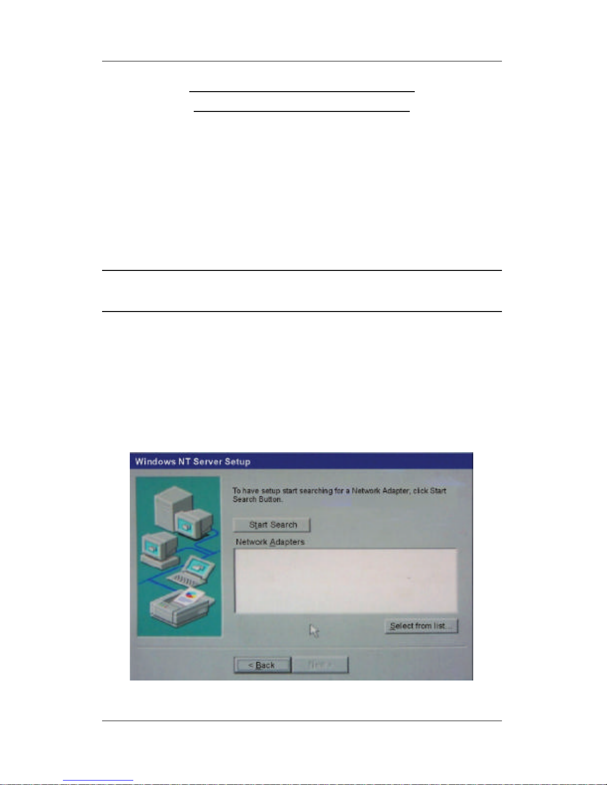
PRO/100+™ LAN Adapter Installation SY-D6IGA
74
Installing the PRO/100+ Driver
When Installing Windows NT
This section describes how to install the PRO/100+ LAN driver when
your are performing a first time Windows NT installation.
The PRO/100+ LAN driver is not embedded in the Windows NT
3.51 and 4.0 operating systems. Therefore, you must install this
driver manually from the PRO/100+ adapter disk or CD.
Note: The PRO/100+ LAN driver for Windows NT (all versions) is
contained in the SOYO CD that ships with your motherboard.
General Instructions
To complete the PRO/100+ LAN driver installation while installing
Windows NT, follow these steps:
1. From the Windows NT Setup screen, select Windows NT
Server Setup.
Page 79
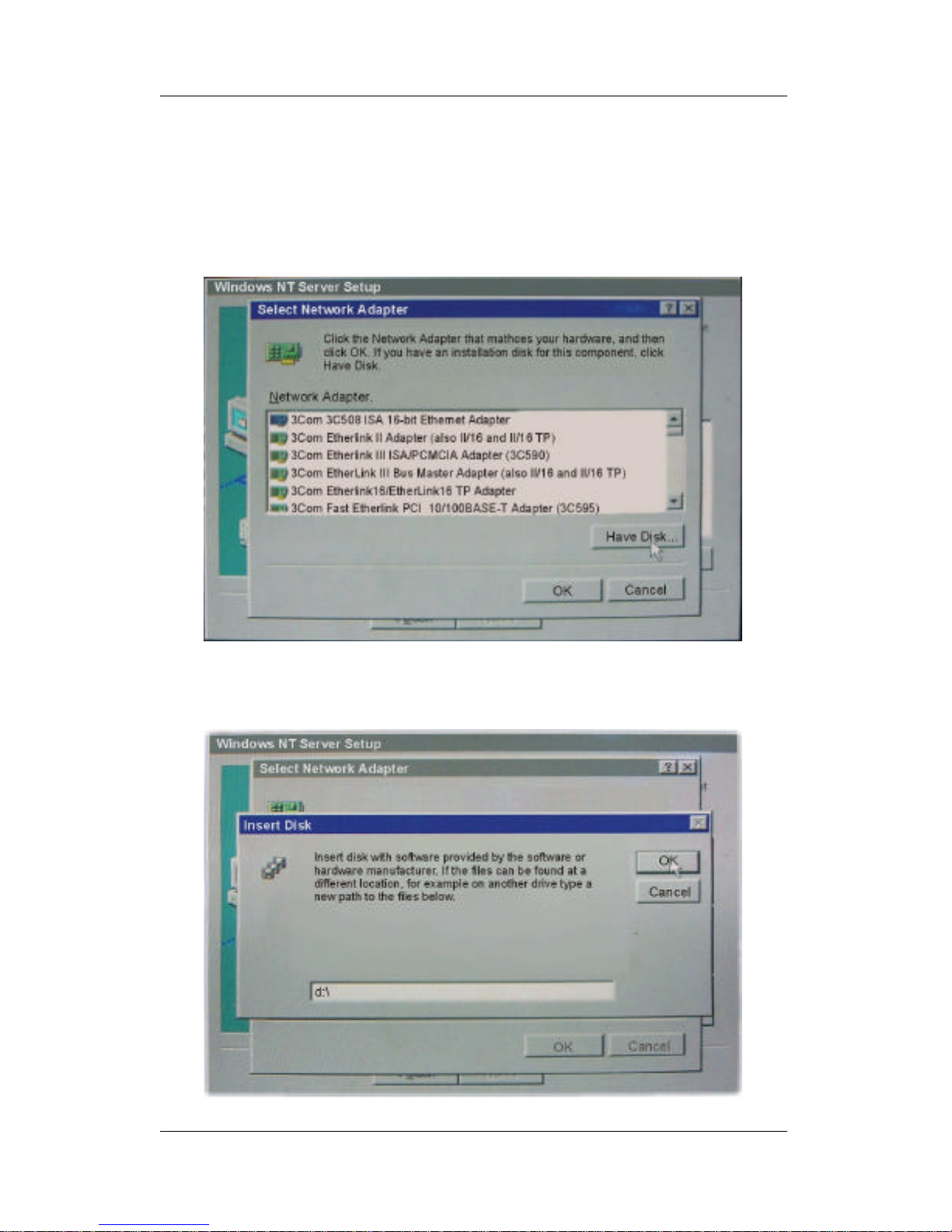
PRO/100+™ LAN Adapter Installation SY-D6IGA
75
2. To begin the search for network adapters in Windows NT
Server Setup, click [Select from list…].
3. The list of network adapters embedded in the Windows NT
installation disk appears.
4. Do not select an adapter from this list. Instead click [Have
Disk…] to select from the driver disk.
Page 80
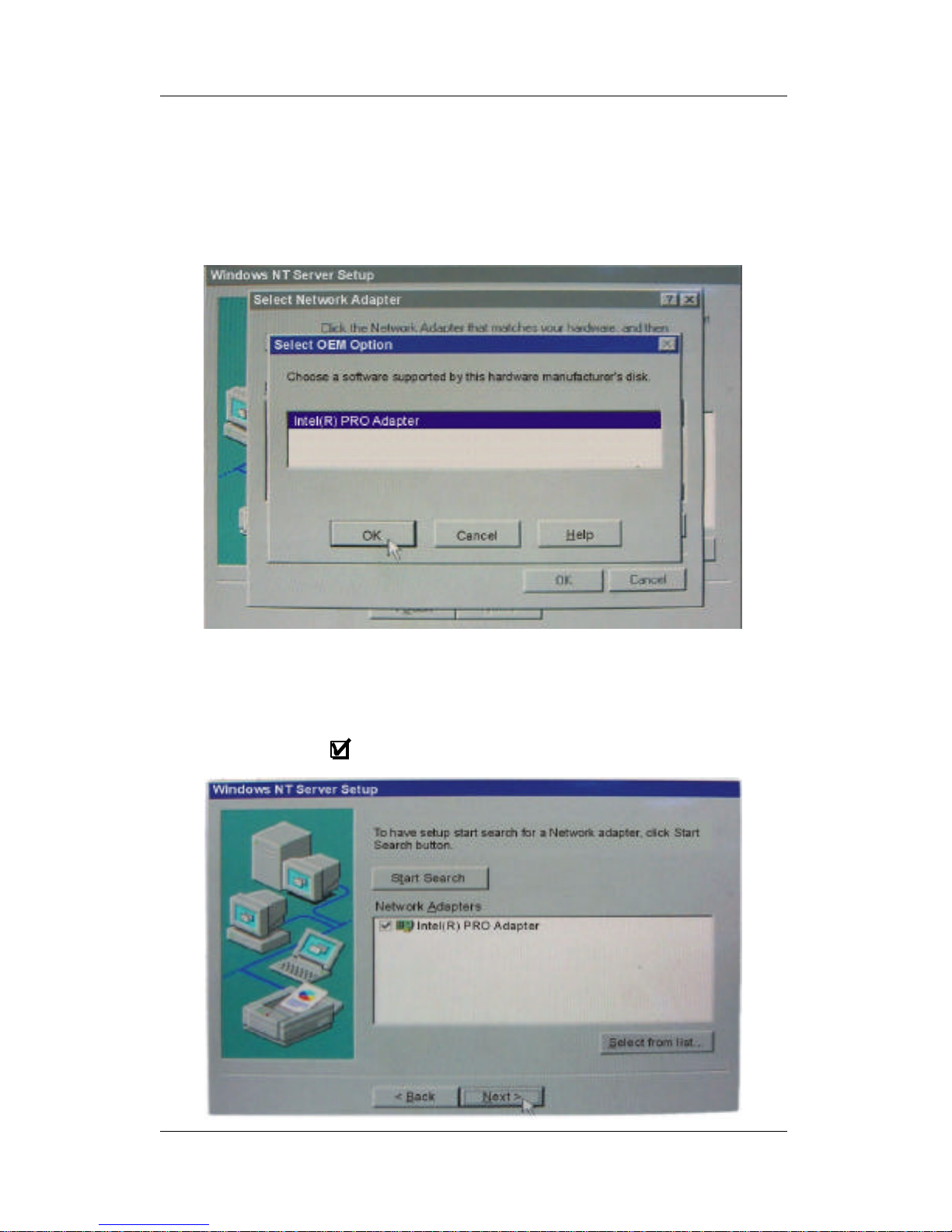
PRO/100+™ LAN Adapter Installation SY-D6IGA
76
5. Type “d:\” in the Insert Disk dialog box, insert the SOYO CD
into the appropriate CD-ROM drive, and click [OK].
6. When the list of adapter appears in the Select OEM Option
dialog box, select Intel® PRO Adapter and click [OK].
7. As Windows NT Server Setup screen returns, make sure that
the Network Adapters dialog box displays Intel® PRO Adapter.
If Intel® PRO Adapter is not checked, click once in the checkbox
to mark it as .
Page 81
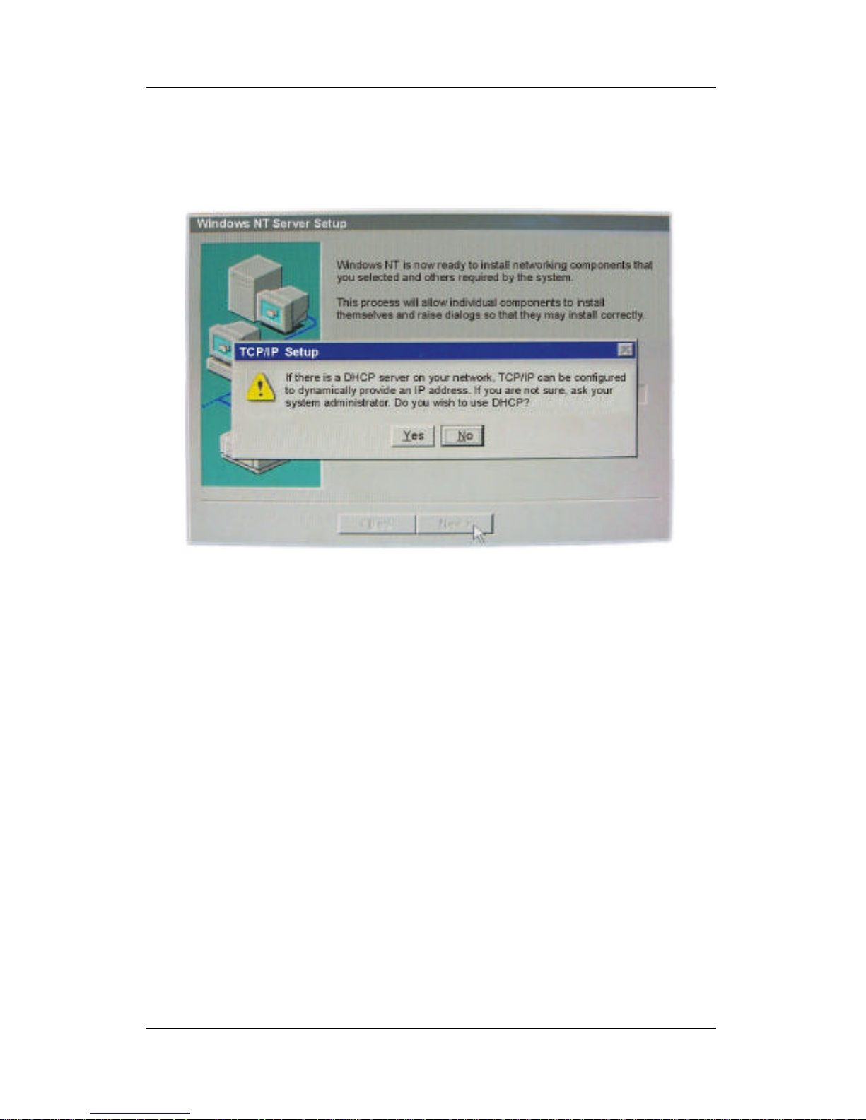
PRO/100+™ LAN Adapter Installation SY-D6IGA
77
8. Click [Next] to complete the driver installation.
9. Take out the SOYO CD and insert the Windows NT Installation
CD to continue the Windows setup process.
Page 82

PRO/100+™ LAN Adapter Installation SY-D6IGA
78
Windows® NT 4.0 Installation Notes
Location of Driver: \ NT\E100BNT.SY_ (NDIS 4.0 compressed)
\OEMSETUP.INF
Note: NT 4.0 ships with a driver for the PRO/100B adapter.
However, you must install the more recent driver from the
PRO/100+ adapter disk or CD.
General Instructions
After installing the adapter in the computer, you will need to
configure it under Windows NT, as instructed below:
1. Double-click the [Network] icon in the [Control Panel].
2. Select the Adapter tab.
3. Click [Add]. You will see a list of adapters.
4. Do not select an adapter from this list. Instead, insert the
PRO/100+ adapter disk or CD into the appropriate drive and
click [Have Disk].
5. Type “D:\” (for CD) or “A:\” (for floppy) in the dialog box and
click [OK]. Then follow the prompts to complete installation.
When the adapter is added you will see a new adapter listed in
the Network Adapters list.
6. Click [Close] to finish and configure any protocols as prompted.
7. Restart Windows NT when prompted.
Page 83

PRO/100+™ LAN Adapter Installation SY-D6IGA
79
Windows® NT 3.51 Installation Notes
Location of Driver: \E100B.SY_ (NDIS 3 compressed)
\OEMSETUP.INF
General Instructions
After installing the adapter in the computer, you will need to
configure it under Windows NT, as instructed below:
1. Double-click the [Network] icon in the [Control Panel].
2. Click the [Add Adapter] button.
3. Do NOT select an Intel adapter from the list. Instead, scroll to
the end of the list and select:
[Other] (Requires disk from manufacturer.)
4. Click the [Continue] button.
5. Insert the Intel PRO/100+ disk or CD into the corresponding
drive, specify that drive, and click [OK].
6. Select the name that corresponds to the adapter you are
installing and click [OK].
7. Click [OK] in the Network Settings dialog. Other configuration
screens may appear. Configure as desired. When prompted,
restart Windows NT.
Note: The NDIS 3 miniport driver will automatically get installed in
Windows NT 3.51.
Page 84

PRO/100+™ LAN Adapter Installation SY-D6IGA
80
Windows® 98 Installation Notes
Location of Driver: \E100BNT5.SY_ (NDIS 5.0 compressed)
Location of Setup File: \NET82557.INF
Manually Adding an Adapter in Windows 98
If the New Hardware Found dialog box does not appear at startup
and you cannot connect to the network, check the Device Manager
list to verify if the new adapter is present. If it is missing from the
Device Manager list, follow these steps to configure the new
adapter:
1. From the [Control Panel], double-click the [System] icon.
2. Click the Device Manager tab.
3. Double-click [Other Devices] or [Network Adapters] in the list area.
4. Double-click a PCI Ethernet Controller.
5. Click the Driver tab, then click [Update Driver].
6. Click [Next] at the Update Device Driver Wizard.
7. Select "Search for a better driver..." and click [Next].
8. Insert the PRO/100+ adapter disk and select "Specify a
location", then enter the appropriate drive for your disk media
(A:, D:\, etc.), and Click [Next].
9. The Update Wizard displays the message that it has found the
driver D:\ NET82557.INF (where D: is your media drive). Click
[Next].
10. Click [Finish].
11. Now restart your computer.
Note: At this point, you may be required to insert the Windows 95/98
CD. Insert the CD when prompted by the system.
Page 85

PRO/100+™ LAN Adapter Installation SY-D6IGA
81
Windows® 95 Installation Notes
Location of Driver: \NT\E100BNT.SY_ (NDIS 4.0 compressed)
Location of Setup File: \NET82557.INF
Determining Your Version of Windows 95
Follow the steps below to determine which version of Windows 95 is
running on your system:
1. Click on the [Start] button.
2. Select [Settings].
3. Select the [Control Panel].
4. Double-click on the [System] icon. The System Properties
dialog box opens.
5. Select the General tab. Information about your system is
displayed, including the version of Windows 95 you are running,
under System.
Advanced Configuration Parameters
An advanced configuration utility called PROSet was installed on
your system when you installed the PRO/100+ adapter. To start
PROSet, double-click on the [PROSet] icon in the Windows control
panel. For additional information, click [Help] in the PROSet window.
The defaults specified for the adapter work correctly for most
configurations. When making changes to any adapter settings, be
sure to use PROSet rather than the Advanced tab under Properties
in the Network control panel.
Page 86

PRO/100+™ LAN Adapter Installation SY-D6IGA
82
Manually Adding an Adapter in Windows 95
(For version 950B Only)
If the New Hardware Found dialog box does not appear at startup
and you cannot connect to the network, check the Device Manager
list to see if the new adapter is present. If it is not, follow these steps:
1. From the [Control Panel], double-click the [System] icon.
2. Click the Device Manager tab.
3. Double-click [Other Devices] (question mark icon) in the list
area.
4. Double-click a PCI Ethernet Controller.
5. Click the Driver tab, then click [Update Driver].
6. Insert the Configuration and Drivers disk or CD in the
appropriate drive, and at the Update Device Driver Wizard,
select [Yes] and click [Next].
7. Select “Network adapter” and click [Next].
8. Click [Have Disk], insert the Configuration and Drivers disk in
the appropriate drive, type “D:\”, and click [OK].
9. At the Select Device dialog box, select “INTEL 82558”,
and click [OK] again.
10. Fill out the correct configuration for your network if Windows
requires such information.
11. Follow any prompts for Windows 95 installation disks and
restart when prompted.
Note: The Windows 95 system files are typically available on the
Windows 95 CD in the “win95” directory (D:\win95).
Page 87
PRO/100+™ LAN Adapter Installation SY-D6IGA
83
Changing Adapter Settings with PROSet™
There are two ways to run PROSet which allows changing the
adapter settings.
l From the Control Panel, double-click on the [PROSet] icon.
l From the Control Panel, double-click on the [Network] icon,
select the Adapters tab, and double-click on the "Intel(R)
PRO/100+ PCI Adapter".
From the main PROSet menu, you can click the Advanced tab to
view and modify adapter settings. The defaults work correctly for
most configurations. The following table lists the PROSet
parameters that can be configured in the Advanced menu.
PROSet
Parameter
Description
Speed
Recommended
Setting
[Auto Detect]
(default)
This parameter lets the PRO/100+ adapter know what speed to use on the Ethernet
connection. The choices are 10 Mbps, 100 Mbps, and Auto Detect.
In Auto Detect mode, the adapter detects if its networking environment can support 100
Mbps speed. It then sets the speed to 100Mbps if so, or otherwise to 10Mbps.
Note: If you want to choose a Duplex Mode other than Auto Detect, you must set the
speed to either 10 Mbps or 100 Mbps.
Duplex
Recommended
Setting
[Auto Detect]
Auto Detect
Auto Detect: The adapter negotiates with the hub or switch how to send/ receive
packets, either full or half duplex.
Full-Duplex: The adapter sends and receives packets at the same time. This improves
the performance of your adapter. Set duplex mode to full duplex only if you have a switch
that also supports full duplex.
Half-Duplex: The adapter performs one operation at a time. It either sends or receives.
Note: In order to allow changing the Duplex mode, you must set the Speed to either 10
Mbps or 100 Mbps.
The PRO/100+ adapter has the ability to send and receive packets at the same time
(full-duplexing) at both 10 and 100 Mbps. In order to reap the benefits of full duplexing,
you MUST have a full duplex hub or switch.
The PRO/100+ adapter has the added ability to "talk" to the hub or switch and determine
at which mode to communicate (either full or half duplex). This is called auto-
negotiation. You must have an auto-negotiating hub or switch to get full duplex support
with the Duplex Mode set to Auto. If you don't have an auto-negotiating hub or switch
and want to run at full duplex, set Duplex Mode to Full and then set the SPEED
parameter to either 100 Mbps or 10 Mbps.
The PRO/100B T4 adapter can not operate in full duplex mode at 100 Mbps.
The PRO/10+ PCI adapter can only operate in full duplex mode at 10 Mbps and only on
the TPE connector. The PRO/10+ PCI adapter does not support auto-negotiation; it will
run at half duplex unless forced.
Other Settings
For information on other settings in the PROSet Advanced tab, use PROSet's
context-sensitive online help.
Page 88

PRO/100+™ LAN Adapter Installation SY-D6IGA
84
Windows® for Workgroups 3.11 Installation Notes
Location of Driver: \WFW\E100B.38_
Location of Setup File:\WFW\OEMSETUP.INF
General Instructions
Before You Begin: If your adapter was shipped with a CD, create
an installation diskette from the CD before starting the installation
procedure. Put the CD into your CD-ROM drive and a blank
formatted diskette into a diskette drive. Run the MAKEMS.BAT from
the MAKEDISK directory on your CD. The command syntax is
MAKEMS <source drive> <destination diskette>.
Example: MAKEMS D: A:
Note: If you are running Novell NetWare on this workstation, see the
Novell NetWare section of Hints and Tips below before continuing
with this installation.
Follow these steps, to perform the installation for Windows
Workgroups 3.11:
1. Double-click the [Network Setup] icon in the Network Group.
2. If you are replacing a previous LAN adapter, click the [Remove]
button to delete that adapter.
3. Click the [Networks] button. Select [Install Microsoft Windows
Network] and click [OK].
Optional 1: To add Novell NetWare support to this workstation, click
[Other], then select [Novell NetWare Shell 3.x] if you are using
NETX, or select [Novell NetWare Shell 4.x] if you use VLMs. Click
[OK].
Optional 2: To share files and printers on this workstation, click the
[Sharing] button, then click on [OK].
Page 89

PRO/100+™ LAN Adapter Installation SY-D6IGA
85
4. Click the [Drivers] button.
5. Click the [Add Adapter] button. Select [Unlisted or Updated
Network Adapter] and click on [OK].
6. Insert the adapter driver disk in the drive and specify the path
<drive>:\WFW for the location of the driver.
7. Select the “Intel PRO/100+ PCI” adapter from the list box and
click [OK].
8. Specify the correct speed for your network. If you are using the
TX-based adapter, specify the correct duplex mode. If you are
unsure of the correct settings, contact your Network
Administrator.
Notice 1: If you set the PRO/100+ TX adapter to FULL duplex and
you are running at 100 Mbps, you must change your speed setting
to 100.
Notice 2: These options will not come up if you already have the
NetWare ODI driver installed. These settings are set in the
NET.CFG file.
9. The driver and default protocols will appear in the Network
Drivers window. If you need to add or remove a protocol, do so
here.
10. In the Network Drivers window, click [Close].
11. In the Network Setup window, click [OK].
12. In the Microsoft Windows Network Names window, enter a
unique user name, the name of your new or existing workgroup,
and a unique computer name for your workstation, then click
[OK].
Page 90

PRO/100+™ LAN Adapter Installation SY-D6IGA
86
13. Choose [Yes To All] when WFW asks if you want to replace the
files currently installed with the versions you are installing now.
14. Insert the WFW disks, as required. If prompted for the NetWare
files, insert the Novell disk containing the drivers for the Novell
file WINDR3.EXE.
If prompted for the path of E100B.386, insert the Configuration
and Drivers disk into a drive and for the path, type:
“A:\WFW” or “D:\WFW” if using the CD-ROM.
If prompted for the path of E100B.DOS, specify: “A:\DOS” or
“D:\DOS” if using the CD-ROM.
15. When finished updating the files, WFW reports that it modified
several files. Click on [OK]. WFW changes your last drive to P:.
If you want to change this setting, do so in your CONFIG.SYS
file. WFW also modifies your NET.CFG file (for NetWare users).
Check this file to make sure your frame types load in the correct
order for your network.
16. When WFW prompts you to restart your computer for the
changes to take effect, click on [Restart Computer].
Hints and Tips
General
1. If you are installing multiple PRO/100 adapters in WFW, follow
the instructions above for installing each adapter. Then, enter
the adapter's 12-digit hexadecimal Ethernet address in the
[IN$E100B] and [IN$E100B1] sections of the PROTOCOL.INI
file. (The Ethernet address is printed on a sticker placed on the
adapter. For dual-port adapters, increment the Ethernet
address by 1 for the Ethernet address of the second port.)
Page 91

PRO/100+™ LAN Adapter Installation SY-D6IGA
87
Novell NetWare
1. Before you begin installing driver support for WFW and Novell
NetWare on the same workstation, you will need these Novell
NetWare files:
NETWARE.DRV,
NETWARE.HLP,
NWPOPUP.EXE,
VIPX.386,
and VNETWARE.386.
You may obtain these files by one of the following ways:
a. Download the self-extracting file WINDR3.EXE from Novell
NetWare forum on CompuServe or Novell's FTP server on
the Internet (ftp.novell.com) or WWW
ftp://ftp.novell.com/pub/updates/nwos/dsclnt12).
b. Contact Novell to have the files sent to you.
c. Contact a Novell NetWare dealer in your area.
2. Set up the workstation to connect to NetWare using the DOS
ODI client driver.
3. Load the ODI driver and login to your NetWare server.
4. Start WFW and set up the driver for the PRO/100+ adapter by
following the instructions shown above. When the driver is
chosen, WFW detects the ODI driver that is already loaded and
automatically installs the appropriate support. Next to the
adapter name in the Network Drivers window, you will see
[ODI/NDIS3], which indicates it recognized the ODI driver.
Page 92

PRO/100+™ LAN Adapter Installation SY-D6IGA
88
PRO/100+™ - All NetWare Products
Installation Notes
Installation Notes for PRO/100+ Server and Client Adapters in
Novell NetWare Operating Systems.
Contents
l Netware 3.12 and 4.10 Server Driver Installation Notes
Ø Sample Load Commands
Ø General Instructions
Ø Hints and Tips
l Netware 3.11 Server Driver Installation Notes
Ø Overview
Ø Sample Load Commands
Ø General Instructions
Ø Hints and Tips
l Netware Client 32 for Windows 95
Ø General Instructions
l Netware Client 32 for DOS/Windows 3.1x
Ø General Instructions
Ø Hints and Tips
Ø Sample Configurations
l Netware OS/2 ODI Client Driver Installation Notes
Ø Sample Configuration Files
Ø Introduction
Ø General Instructions
Ø Hints and Tips
Ø NET.CFG Optional Parameters
Ø Detailed Example
l Netware DOS ODI Client Driver Installation Notes
Ø Quick Installation
Ø Sample Configuration Files
Ø General Installation for NetWare 3.11/3.12 Clients
Ø General Installation for NetWare 4.1/3.12 Client with VLMs
Ø NET.CFG Optional Parameters
Ø Detailed Example
l Netware Client Services for Windows NT 4.0 Using ODI
Server Driver
Ø General Instructions
Page 93

PRO/100+™ LAN Adapter Installation SY-D6IGA
89
Netware 3.12 and 4.10 Server Driver
Installation Notes
Location of driver: \NWSERVER\3X4X.OLD\E100B.LAN
(ODI Assembly Specification version 3.3)
Location of NLMs: On Novell's automated services
(ODI33F.EXE or greater)
Note: ODI33x.EXE is a Novell archive that contains the latest server
NLMs and support files. The x in ODI33x.EXE is subject to change
with each new release of the archive.
These instructions are for use with the ODI Assembly Specification
v3.31 NLMs. The \NWSERVER\E100B.LAN driver on this disk is
written to this specification. To load the driver on NetWare 4.10 or
3.12 requires updated ETHERTSM, MSM and the new NBI.NLM.
Obtain these files from Novell's automated services.
l For NetWare 4.10:
Ø NBI.NLM (ver 1.64, 08/29/97 or newer)
Ø MSM.NLM (ver 3.71, 12/02/97 or newer)
Ø ETHERTSM.NLM (ver 3.61, 12/08/97 or newer)
l For NetWare 3.12:
Ø NBI31X.NLM (ver 1.64, 08/29/97 or newer)
Ø MSM31X.NLM (ver 3.71, 12/02/97 or newer)
Ø ETHERTSM.NLM (ver 3.61, 12/08/97 or newer)
Notice1: NBI.NLM (or NBI31X.NLM) must be loaded before MSM
and ETHERTSM.
Notice2: NetWare 3.12 needs MSM31X.NLM renamed to
MSM.NLM.
Page 94

PRO/100+™ LAN Adapter Installation SY-D6IGA
90
Important: When using command line options with the .LAN driver
for NWSERVER, make sure the equal sign is followed by a value.
Otherwise, unpredictable results may occur.
General Instructions
1. Install NetWare 3.12 or 4.10 according to the NetWare
instructions.
2. Copy the PRO/100+ server driver (\NWSERVER\E100B.LAN)
and any updated NLMs, to the NetWare server's hard drive.
l If you can't log in to the server (before starting the server)
copy the E100B.LAN driver from the \NWSERVER
directory on the Configuration and Drivers disk to the root
directory of the server's hard drive.
l If you can log into the server, copy the driver to the
SYSTEM subdirectory. If you do this, you won't need to
specify a path on the load line. If you copy it to another
directory, make sure the LOAD statement includes the
correct path.
3. Start the server. At the server console, load NBI, MSM and
ETHERTSM (for NetWare 3.12 load NBI31X, MSM31X and
ETHERTSM) in this order.
Next, load and bind the server driver as follows:
LOAD C:<PATH>\E100B SLOT=x FRAME=ETHERNET_802.2
BIND IPX TO E100B NET=xxxxxxxx
Where:
SLOT=x Specifies the NBI (NetWare Bus Interface) slot
number. Substitute x with the valid value for the adapter. You
will be prompted with the slot number(s) of installed PRO/100+
adapters. The NBI numbers are different from the slot number
indicated in the SETUP.EXE utility.
Page 95

PRO/100+™ LAN Adapter Installation SY-D6IGA
91
NET=xxxxxxxx is the unique network address for that LAN
segment.
The default frame type is 802.2. If your workstation needs to
use the 802.3 frame type, see the section later in this document
about using multiple frame types on one adapter.
4. Add the load and bind statements you need to the server's
AUTOEXEC.NCF file so the PRO/100+ adapter driver loads
automatically each time the server starts.
Hints and tips
1. If the error message:
"Loader cannot find public symbol: <symbol name>"
is encountered then:
Upgrade the ETHERTSM.NLM and MSM31x.NLM and be sure
to rename MSM31x.NLM to MSM.NLM.
2. Installing multiple adapters:
If you have multiple adapters in a single server, each adapter
must have a different NET number and SLOT number. Also,
you may want to name each adapter. For example:
LOAD C:\E100B SLOT=3 NAME=LAN_A
BIND IPX TO LAN_A NET=222
LOAD C:\E100B SLOT=4 NAME=LAN_B
BIND IPX TO LAN_B NET=333
3. If you have problems loading the driver on multiple adapters
and the initialization fails due to "Insufficient RCBs," increase
the number of buffers allocated to the server. Add the following
to STARTUP.NCF:
SET MINIMUM PACKET RECEIVE BUFFERS = 100 (or larger)
SET MAXIMUM PACKET RECEIVE BUFFERS = 500 (or larger)
Page 96

PRO/100+™ LAN Adapter Installation SY-D6IGA
92
The MINIMUM value you specify must be at least 30 times the
number of PRO/100+ adapters in the computer. Recommended
settings are:
1-3 adapters: 100
4 adapters: 150
The MAXIMUM you can specify depends on the amount of
memory in the server, but it must be greater than the
MINIMUM.
4. Installing one adapter with multiple frame types:
When binding multiple frame types to one adapter, enter a
LOAD and BIND statement for each frame type. Each LOAD
statement uses the same SLOT number, but each BIND
statement needs a unique network number.
You must also include a name on each load line to avoid being
prompted for the adapter to bind IPX to.
Example:
LOAD C:\E100B SLOT=3 FRAME=ETHERNET_802.2 NAME=LAN8022
BIND IPX TO LAN8022 NET=88888
LOAD C:\E100B SLOT=3 FRAME=ETHERNET_802.3 NAME=LAN8023
BIND IPX TO LAN8023 NET=77777
5. Optional LOAD line parameters:
See the NetWare Server Parameters readme (NWPARAM.TXT)
for additional information.
Page 97

PRO/100+™ LAN Adapter Installation SY-D6IGA
93
Netware 3.11 Server Driver Installation Notes
Location of driver: \NWSERVER\311LAN\E100B.LAN
(ODI 3.2 Assembly Specification driver)
Location of NLM's: On Novell's automated services.
ETHERTSM.NLM 04-18-95
LSLENH.NLM 12-21-94
PATCHMAN.NLM 01-22-96
MSM31X.NLM 11-23-94
MONITOR.NLM 10-26-92 (v1.75 or higher,
otherwise abends will occur)
Note: NetWare 3.1x needs MSM31X.NLM renamed to MSM.NLM.
Overview
NetWare 3.11 requires an ODI 3.2 Assembly Specification driver.
This driver is in the \NWSERVER\311LAN\ directory of the
Configuration and Drivers disk. The directory contains the following
files:
l E100B.LAN (3.2 spec server driver)
l E100B.LDI (Installation file)
l NW311.TXT (This file)
Sample Load Commands
Ø LOAD C:<PATH>\PATCHMAN
Ø LOAD C:<PATH>\LSLENH
Ø LOAD C:<PATH>\MSM
Ø LOAD C:<PATH>\ETHERTSM
Ø LOAD C:<PATH>\E100B SLOT=n FRAME=ETHERNET_802.3
Ø BIND IPX TO E100B NET=xxxxxxxx
Page 98

PRO/100+™ LAN Adapter Installation SY-D6IGA
94
General Instructions
1. Install NetWare 3.11 according to the NetWare 3.11 installation
manual.
2. Copy the E100B.LAN server driver and any updated NLMs to
the NetWare server's hard drive.
l If you can't log in to the server (before starting the server)
copy the E100B.LAN driver to the root directory of the
server's hard drive.
l If you can log into the server, copy the files to the SYSTEM
subdirectory. If you do this, you won't need to specify a
path on the load line. If you copy it to another directory,
make sure the LOAD statement includes the correct path.
3. Modify the server's STARTUP.NCF to pre-allocate server
buffers with the following:
SET MAXIMUM PHYSICAL RECEIVE PACKET SIZE = 2048 (or larger)
4. Start the server. At the server console, issue the load and bind
statement.
LOAD C:<PATH>\PATCHMAN
LOAD C:<PATH>\LSLENH
LOAD C:<PATH>\MSM
LOAD C:<PATH>\ETHERTSM
LOAD C:<PATH>\E100B SLOT=x FRAME=ETHERNET_802.3
BIND IPX TO E100B NET=xxxxxxxx
Where:
SLOT=x specifies the PCI device number. Substitute x with the
valid value for the adapter. You will be prompted if you don't
specify a slot number.
NET=xxxxxxxx is the unique network address for that LAN
segment.
The default frame type is 802.2. If your workstations needs to
use the 802.3 frame type, see the section later in this document
about using multiple frame types on one adapter.
Page 99

PRO/100+™ LAN Adapter Installation SY-D6IGA
95
5. Add the load and bind statements you need to the server's
AUTOEXEC.NCF file so the PRO/100+ adapter driver loads
automatically each time the server starts.
Hints and Tips
1. Installing multiple adapters:
If you have multiple adapters in a single server, each adapter
must have a different NET number and SLOT number. Also,
you may want to name each adapter. For example:
LOAD C:\E100B SLOT=3 NAME=LAN_A
BIND IPX TO LAN_A NET=222
LOAD C:\E100B SLOT=4 NAME=LAN_B
BIND IPX TO LAN_B NET=333
2. If you have problems loading the driver on multiple adapters
and the initialization fails due to "Insufficient RCBs," increase
the number of buffers allocated to the server.
Add the following to STARTUP.NCF:
SET MINIMUM PACKET RECEIVE BUFFERS = 100 (or larger)
SET MAXIMUM PACKET RECEIVE BUFFERS = 500 (or larger)
The MINIMUM value you specify must be at least 30 times the
number of PRO/100+ adapters in the computer.
Recommended settings are:
1-3 adapters: 100
4 adapters: 150
The MAXIMUM you can specify depends on the amount of
memory in the server, but it must be greater than the
MINIMUM.
3. Installing one adapter with multiple frame types:
When binding multiple frame types to one adapter, enter a
LOAD and BIND statement for each frame type. Each LOAD
statement uses the same SLOT number, but each BIND
statement needs a unique network number.
Page 100

PRO/100+™ LAN Adapter Installation SY-D6IGA
96
You must also include a name on each load line to avoid being
prompted for the board to bind IPX to.
Example:
LOAD C:\E100B SLOT=3 FRAME=ETHERNET_802.2 NAME=LAN8022
BIND IPX TO LAN8022 NET=88888
LOAD C:\E100B SLOT=3 FRAME=ETHERNET_802.3 NAME=LAN8023
BIND IPX TO LAN8023 NET=77777
4. Optional LOAD line parameters:
See readme NWPARAM.TXT titled NetWare Server
Parameters for additional information.
 Loading...