


GB
Operating Manual
Stud welding device
SRM technology
BMK-8i
Stud welding gun PH-9 SRM12
PH-3N SRM

GB
Device numbers
We recommend registering the device numbers here so they can be quickly accessed if service is needed.
Operating manual
Document no.: P00158, 01-2016, translation of the original manual
(English: P00258)
All information in this document is the property of
Heinz Soyer Bolzenschweißtechnik GmbH.
Device Type Serial number
Stud welding device BMK-8i
Stud welding gun PH-9 SRM12
PH-3N SRM
Revision status
Document Created/modified Editor Date
Original Prepared DD 14.01.2016

Operating Manual Soyer Bolzenschweißtechnik 3
CONTENTS
1. General information . . . . . . . . . . . . . . . . . . . . . . . . . . . . . . . . . . . . . . . . . . . . . . . 6
1.1. Validity of the operating manual 6
1.2. Registered trademarks 6
1.3. Abbreviations and definitions 6
1.4. Declarations of conformity 7
1.5. Manufacturer 9
1.6. Instruction, training 9
1.7. Standards and directives 9
2. Important safety instructions . . . . . . . . . . . . . . . . . . . . . . . . . . . . . . . . . . . . . . 10
2.1. Safety alerts used 10
2.2. General safety instructions 11
2.3. Safety instructions for the working method 14
2.4. Personal protection equipment 15
2.5. Intended use of the stud welding device 16
2.5.1 Incorrect use 16
2.6. Intended use of the stud welding guns 16
2.6.1 Incorrect use 16
2.7. Operating company prerequisites 17
2.7.1 Requirements for personnel 17
3. Transport . . . . . . . . . . . . . . . . . . . . . . . . . . . . . . . . . . . . . . . . . . . . . . . . . . . . . . 18
4. Storage, shutdown. . . . . . . . . . . . . . . . . . . . . . . . . . . . . . . . . . . . . . . . . . . . . . . 18
5. Disposal . . . . . . . . . . . . . . . . . . . . . . . . . . . . . . . . . . . . . . . . . . . . . . . . . . . . . . . 18
6. Description of the BMK-8i stud welding device . . . . . . . . . . . . . . . . . . . . . . . 19
6.1. Type designation 19
6.2. Working method 19
6.2.1 Stud welding with SRM technology 20
6.2.2 Drawn arc stud welding technology with shielding gas 20
6.3. Overview of the controls 22
6.3.1 Display and setting area 24
6.4. Technical data of the BMK-8i stud welding device 25
6.5. Permitted stud welding guns 26

4 Operating Manual Soyer Bolzenschweißtechnik
CONTENTS
6.6. Cleaning the stud welding device 27
7. Description of the SRM stud chuck . . . . . . . . . . . . . . . . . . . . . . . . . . . . . . . . . 28
7.1. Setting the SRM stud chuck 28
8. Description of the PH-9 SRM12 stud welding gun . . . . . . . . . . . . . . . . . . . . . 30
8.1. Technical data of the PH-9 SRM12 stud welding gun 31
8.2. Replacing the SRM stud chuck in PH-9 SRM12 32
8.3. Replacing the SRM12 support pipe insert with PH-9 SRM12 34
8.4. Cleaning the stud welding gun 35
9. Description of the PH-3N SRM stud welding gun . . . . . . . . . . . . . . . . . . . . . . 36
9.1. Technical data of PH-3N SRM stud welding gun 37
9.2. Replacing the SRM stud chuck with PH-3N SRM 38
9.3. Cleaning the stud welding gun 40
10. Setup and connection . . . . . . . . . . . . . . . . . . . . . . . . . . . . . . . . . . . . . . . . . . . 41
10.1. Requirements for the installation location 41
10.2. Connection of the stud welding device and the stud welding guns 42
10.2.1 Mains connection 42
10.2.2 Connecting the earth cable 42
10.2.3 Connecting the stud welding gun 43
10.2.4 Connecting the shielding gas supply 43
11. Settings . . . . . . . . . . . . . . . . . . . . . . . . . . . . . . . . . . . . . . . . . . . . . . . . . . . . . . . 47
11.1. Setting the welding parameters 47
11.1.1 Help tables for device setting 47
11.1.2 Setting the welding current and the welding time 49
11.1.3 Setting/deactivating the SRM current 50
11.1.4 Setting the gas preflow time 51
11.1.5 Setting the lift time (height of lift) in "Setup" mode 52
12. Welding operation . . . . . . . . . . . . . . . . . . . . . . . . . . . . . . . . . . . . . . . . . . . . . . 54
12.1. Carrying out welding 54
12.2. Notes on checking the quality of the weld 56
12.2.1 Visual inspection 56
12.3. Switching off the device 57
12.4. Weld defects and their causes 58

Operating Manual Soyer Bolzenschweißtechnik 5
CONTENTS
13. Maintenance and repair . . . . . . . . . . . . . . . . . . . . . . . . . . . . . . . . . . . . . . . . . . 62
14. Service . . . . . . . . . . . . . . . . . . . . . . . . . . . . . . . . . . . . . . . . . . . . . . . . . . . . . . . 62
15. Warranty conditions . . . . . . . . . . . . . . . . . . . . . . . . . . . . . . . . . . . . . . . . . . . . 62

General information
6 Operating Manual Soyer Bolzenschweißtechnik
1. General information
This operating manual contains important information and requirements for operating the devices. Keep the operating manual in a readily accessible location
close to the devices.
The term 'devices' in the operating manual refers to the stud welding device and
the stud welding gun.
Carefully read through the operating manual and the other documents contained
in the technical documentation. In particular, comply with the safety instructions
which are intended to help you recognise any residual risks and prevent hazards.
The drawings and diagrams in this operating manual help illustrate the content
and may vary slightly from the actual equipment.
The manufacturer reserves the right to make technical changes.
1.1 Validity of the operating manual
This operating manual applies to the following devices:
1.2 Registered trademarks
The following terms in this manual are marked with registered trademarks:
1.3 Abbreviations and definitions
Essential abbreviations or designations in this manual:
Stud welding device BMK-8i
Stud welding guns PH-9 SRM12
PH-3N SRM
SRM®: SRM stands for magnetic field stud welding and refers to welding
or stud welding in a radially symmetrical magnetic field.
SOYER®: Developments/technologies of Soyer GmbH.
HZ-1 threaded studs: SOYER universal studs with centring tip.
MF threaded studs: SOYER threaded stud with a reduced flange diameter
(MF stands for mini flange).

General information
Operating Manual Soyer Bolzenschweißtechnik 7
1.4 Declarations of conformity
The devices are built according to the generally accepted codes of practice.
i
Please note that significant modifications to the device can void the
declaration of conformity.
In addition, the manufacturer warranty coverage may be rendered invalid.

General information
8 Operating Manual Soyer Bolzenschweißtechnik
Stud welding device
Heinz Soyer Bolzenschweißtechnik GmbH
Inninger Straße 14
82237 Wörthsee
CE Declaration of Conformity
We herewith declare that the machine described in the following and the version available on the
market correspond in design and construction to the safety and health requirements of the listed
guidelines and standards. Any unauthorised modification to this machine automatically annuls this
declaration.
Designation of machine :
Stud welding device
Machine type :
BMK-8i
Machine no. : ______________________
Applicable EU directives : RoHS Directive (2011/65/EU)
Low Voltage Directive (2014/35/EU)
EMC Directive (2014/30/EU)
Applied harmonised : EN 60 974-1:2012
standards, in particular EN 60 974-10:2008
Applied national standards : DGUV Regulation 1
Date : 17 May 2016
Producer’s signature : ____________________
Signer’s function : Managing Director

General information
Operating Manual Soyer Bolzenschweißtechnik 9
1.5 Manufacturer
The manufacturer of the devices is:
Heinz Soyer Bolzenschweißtechnik GmbH
Inninger Straße 14
82237 Wörthsee
Tel.: 0049-8153-885-0
Fax: 0049-8153-8030
Mail: info@soyer.de
Web: www.soyer.de, www.soyer.com
1.6 Instruction, training
Soyer offers optional and individual instruction in the operation of the devices.
Soyer also offers training for customer-specific use of the devices.
Information about the scope and costs of instruction and training can be obtained
from Soyer GmbH.
1.7 Standards and directives
The following standards (among others) must be observed for carrying out stud
welding work and for the qualification of personnel:
• DIN EN ISO 14555 Welding - Arc stud welding of metallic materials
• DIN EN ISO 14732 Welding personnel - Qualification testing of welding operators and weld setters for mechanized and automatic welding of metallic materials
• DIN EN 60974-9 Arc welding equipment - Part 9: Installation and use
• DVS data sheet 0904 Practical tips - Arc stud welding

Important safety instructions
10 Operating Manual Soyer Bolzenschweißtechnik
2. Important safety instructions
Read the following chapters carefully and follow the safety instructions. If you are
uncertain or an instruction cannot be followed, please contact the manufacturer.
The devices have been built according to the generally accepted codes of practice and in compliance with, and application of, the usual and established safety
requirements. To achieve the maximum possible safety, it is essential that all of
the safety instructions in this operating manual are heeded and followed.
2.1 Safety alerts used
Warning signs are used in this document, depending on the potential danger of
the situation.
Safety and information symbols used in this manual
This safety alert indicates an imminently hazardous
situation which will result in serious injury or death.
This safety alert indicates a potentially dangerous
situation which could result in serious physical
injury or death.
This safety alert indicates a potentially hazardous
situation which could result in minor or moderate
injury.
This alert, without the triangle, is also used for
potentially hazardous situations which will result in
property damage.
Additional information indicating danger from electric current. The additional information is used in
conjunction with a warning sign.
Additional information on the risk of burns. The
additional information is used in conjunction with a
warning sign.
Do not touch the surface of the housing, danger of
electrocution.
Do not touch or open, danger for unauthorised persons.
Danger for persons with a heart pacemaker or
other medical implants.
The info sign is not a safety alert. It indicates important and useful information on the subject.
DANGER
!
WARNINGWARNING
!
CAUTIONCAUTION
!
i

Important safety instructions
Operating Manual Soyer Bolzenschweißtechnik 11
Safety instructions on the device
There may be warning stickers on the devices as additional warnings of danger.
The warning stickers are affixed by the manufacturer and must not be removed.
If a warning sticker is damaged and thus illegible, a new warning sticker must be
affixed immediately.
The warning stickers must be obtained from the manufacturer.
2.2 General safety instructions
DANGER
!
Danger due to electric current, general information
When working on current-carrying components, there is a danger to life from
electric current.
• Work on electrical or electronic modules may only be carried out by electrotechnically qualified personnel and carried out in line with the currently
applicable electrotechnical regulations.
• Protection equipment must not be manipulated or disabled. Protection
equipment includes, for example, the housing and housing cover, fuses
and device switches.
• If protection devices have to be removed for maintenance work, the device
must only be switched on again when all protection devices are mounted
again and their functionality has been checked.
• Starting the device with defective protection equipment is not allowed.
Repair or replace faulty protection equipment immediately. Unwanted
operation by a third party must be prevented.
Important safety instructions
12 Operating Manual Soyer Bolzenschweißtechnik
DANGER
!
Danger from electric current during maintenance and repair
When working on current-carrying components, there is a danger to life from
electric current.
• Work on electrical or electronic components must only be carried out by
electrical specialists from Soyer Bolzenschweißtechnik.
• Before working on the stud welding device, the mains switch of the device
must be switched off and the mains plug of the stud welding device disconnected.
• Before working on the stud welding gun, the supply cable to the stud welding device must be disconnected.
• If protection devices have to be removed for maintenance work, the device
must only be switched on again when all protection devices are mounted
again and their functionality has been checked.
DANGER
!
Danger from magnetic fields
Strong magnetic fields occur in the area of the device, which may affect the
operation of medical aids, causing a danger to life.
• Persons with electrical medical aids (such as pacemakers) must keep
away from the devices.
• The operating personnel must ensure that persons with medical aids keep
away from the devices.
DANGER
!
Danger of explosion from an inappropriate installation location in explosive atmospheres
The device is not designed for use in explosive zones.
• The device may not be installed and operated in explosive atmospheres.

Important safety instructions
Operating Manual Soyer Bolzenschweißtechnik 13
CAUTIONCAUTION
!
Danger of burns due to hot surfaces
Through the welding process, the workpieces and some parts of the welding
gun become so hot that touching them can lead to burns.
• Always use personal protective equipment.
• Before beginning work on hot parts of the device, check that they have
cooled down.
• Do not hold the gun tight in the welding area.
WARNINGWARNING
!
Danger of burns from hot welding spatter
Dangerous welding spatter can occur during the welding process.
• Always use personal protective equipment.
WARNINGWARNING
!
Danger of burns from hot welding spatter
Welding spatter or hot workpieces occurring due to the welding process can
result in a danger of burns.
• Do not store any inflammable and combustible materials in the welding
area.
Important safety instructions
14 Operating Manual Soyer Bolzenschweißtechnik
2.3 Safety instructions for the working method
WARNINGWARNING
!
Hazards due to incorrect working method
Hazards for operators and third parties can arise due to an incorrect working
method.
• Ensure sufficient stability and a dry installation location for the stud welding
device.
• Make sure not to knock over the stud welding device or to pull it down from
its emplacement with the cables of the gun.
• Make sure, especially with mobile use, of your own good stability during
welding.
• Do not hold the workpiece in your hands during welding. The workpiece
must be securely fixed during the welding process.
• Never wrap the gun lines around parts of your body (e.g. arm) as electric
fields can occur.
• If the gun is not put on properly or the gun settings are incorrect, a flash
can occur during welding. Do not look directly into the flash.
• The gun carries out lifting movements during the welding process. Do not
hold the gun tight in the area of moving parts.

Important safety instructions
Operating Manual Soyer Bolzenschweißtechnik 15
2.4 Personal protection equipment
The wearing of personal protective equipment is recommended when working
with the stud welding device.
WARNINGWARNING
!
Danger due to missing or incorrect personal protection kit
There is a danger of burns during stud welding, especially due to hot welding
spatter. A danger of blinding can also arise due to the occurrence of strong
arcs.
• Always wear suitable, closed protective clothing.
• The extent of the protective equipment depends on the respective occurrence and intensity of the welding spatter, arcs and/or noise. This varies
according to the basic material, stud material, stud size and required welding power.
• Heed the instructions concerning protective equipment in the following
overview.
Recommended personal protection equipment
Protective goggles
During welding, welding spatter and a flash occur. Wear
suitable safety goggles with side protection and protect
your eyes with filter protection if necessary.
Protective gloves
During welding, the workpieces and parts of the welding
gun become hot, as well as the occurrence of welding spatter. Wear suitable, non-combustible, heat-resistant protective gloves.
Protective clothing
Welding spatter occurs during welding. Wear suitable, noncombustible and, if necessary heat-resistant, protective
clothing.
Safety shoes
Welding spatter occurs during welding. Wear suitable, noncombustible, heat-resistant safety shoes.
Hearing protection
Depending on the welding device and the welding application, relatively loud welding noise can occur. Wear suitable
hearing protection.

Important safety instructions
16 Operating Manual Soyer Bolzenschweißtechnik
2.5 Intended use of the stud welding device
Pins and threaded studs from M3 - M8 (M6 and M8 preferred), made of steel and
stainless steel, can be welded using the SOYER BMK-8i stud welding device.
Special studs or diameters on request.
The stud welding device must only be operated with the welding guns described
in Chapter "6.4 Technical data of the BMK-8i stud welding device" on page 25.
The stud welding device must be operated within the technical specifications.
Only welding studs from Soyer (HZ-1 and MF types) must be welded.
The stud welding device supports the following welding processes:
• SRM welding (stud welding in a radially symmetrical magnetic field)
• Drawn arc stud welding with shielding gas
2.5.1 Incorrect use
Any use other than the intended use of the device is deemed to be non-intended.
Use other than intended use, unauthorised modification or manipulation of the device will void the Declaration of Conformity as well as all warranty claims against
the manufacturer.
2.6 Intended use of the stud welding guns
Pins and threaded studs from M3 to M12 and numerous different weld fasteners
according to DIN EN ISO 13918, made of steel, stainless steel, aluminium and
brass, can be welded with the SOYER stud welding guns described in this operating manual.
Special studs or diameters on request.
The operation of welding guns is only permitted with the stud welding devices described in the technical data of the gun.
The stud welding gun must be operated within the technical specifications.
2.6.1 Incorrect use
Any use other than the intended use of the welding gun is deemed to be contrary
to the intended use.
Use other than the intended use, unauthorised modification or manipulation of the
device will void the Declaration of Conformity as well as all warranty claims
against the manufacturer.
i
The maximum diameter and type of weldable studs can be limited by the
performance capacity of the stud welding device on which the gun is
operated.

Important safety instructions
Operating Manual Soyer Bolzenschweißtechnik 17
Misuse of the welding gun as a tool, e.g. as a hammer for checking the weld quality, is not permitted.
2.7 Operating company prerequisites
The operator of the device must ensure that the preconditions in this operating
manual are fulfilled for safe operation.
These include, for example, the conditions at the installation site, the official regulations on requirements for a safe workplace, the training of the operating personnel and qualified personnel in handling the device if necessary, fulfilment of
the prescribed maintenance work, and monitoring that the device is used in conformity with intended use.
The operating manual must be stored in the vicinity of the device.
The device operating company must ensure that the device is only used when all
protective equipment is present, active and undamaged.
2.7.1 Requirements for personnel
Operating personnel
The personnel responsible for operating the device in normal operation must be
familiar with the device and trained accordingly. They must have read and understood the operating manual. In addition, they must be capable of eliminating (or
minimising as far as possible) any possible remaining danger to themselves and
third parties when working with the device.
To retain this qualification, the safety training must be repeated at least once a
year. In the event of a fault or if maintenance becomes necessary, consult specially trained qualified personnel or the manufacturer.
Operators of stud welding equipment must have the expert knowledge for operating, correctly setting the equipment and for properly carrying out the welding.
If the welders have to be qualified for certification of welding, the
DIN EN ISO 14555 and DIN EN ISO 14732 standards must be observed.
Electrical and
electronic specialists
The following basically applies: Work on current-carrying elements may only be
performed by qualified electricians. The work must be carried out in line with the
applicable technical rules for electrotechnical devices.
i
All devices of Soyer Bolzenschweißtechnik GmbH must only be opened
by Soyer personnel or by personnel authorised by Soyer.

Transport
18 Operating Manual Soyer Bolzenschweißtechnik
3. Transport
When transporting the device, make sure it cannot be damaged. It must be protected against the effects of weather, especially moisture, through suitable packaging.
4. Storage, shutdown
Protect the device against dirt and humidity during storage or shutdown.
Protect the device against unauthorised access by third parties.
5. Disposal
Local environmental guidelines for disposal must be complied with.
Substances that are hazardous to water and the environment must be disposed
of in accordance with legal regulations.
Materials must be separated according to regulations where applicable.

Description of the BMK-8i stud welding device
Operating Manual Soyer Bolzenschweißtechnik 19
6. Description of the BMK-8i stud welding device
The main elements of the stud welding device are shown and the function described in the following.
6.1 Type designation
6.2 Working method
Pins and threaded studs from M3 - M8 (M6 and M8 preferred) made of steel and
stainless steel can be welded using the SOYER BMK-8i stud welding device.
Only welding studs from Soyer (HZ-1 and MF types) must be welded.
The BMK-8i working with SRM technology was specially developed for mobile
use.Thanks to SRM, the BMK-8i mobile welding device enables problem-free
welding, even in constrained positions.
The BMK-8i works on the basis of a compact inverter current source and delivers
a constant welding current up to 300 A with extremely short welding times. The
rectified mains voltage is converted into a high frequency voltage with a frequency
of 75 kHz by an Insulated Gate Bipolar Transistor-based (IGBT-based) inverter.
The energy is transferred by a high frequency transformer and rectified on the output side. As a result of the high control speed in combination with the integrated
SRM welding process of the BMK-8i, the reproducibility of the welds is increased
and the quality of the welding significantly improved.
The PH-9 SRM12 stud welding gun or the PH-3 SRM stud welding gun (via an
adapter) can be connected as a standard gun to the BMK-8i stud welding device.
Designation
Order number
Feature
BMK-8i
P01363
Mains voltage 230 V 1PH/N/PE

Description of the BMK-8i stud welding device
20 Operating Manual Soyer Bolzenschweißtechnik
6.2.1 Stud welding with SRM technology
The welding process recommended by Soyer for operating the BMK-8i is the patented SRM welding process (patent no.: 10 2004 051 389) in conjunction with the
also newly developed HZ-1 universal studs with flat front face and centring tip
(patent no.: 10 2006 016 553).
SRM means stud welding in a radially symmetrical magnetic field.
This innovative weld technology allows welds in a ratio of 1:10 of the sheet thickness to the stud diameter (previously 1:4) where the use of ceramic rings can be
dispensed with.
The versatile advantages of the SRM process provides completely new application options in the entire stud welding sector (additional information available at
www.srm-technology.de).
Functional principle
The advantages of the SRM welding process are:
• No bothersome weld bead
• Welding from constrained positions now also without ceramic ring
• Reduced weld penetration in the plate
• Lower energy consumption and reduced welding time
• No welding spatter
6.2.2 Drawn arc stud welding technology with shielding gas
For drawn arc stud welding with shielding gas, a gas mixture of 82% argon and,
for example, 18% CO2 (e.g. Corgon®18*) is used as an aid.
This shielding gas shields the weld point from the atmosphere and takes over the
weld pool backing at the same time. It also forms a concave fillet weld-shaped
weld bead with a metallic surface without discolouration, which reduces the risk
of corrosion and achieves better dynamic characteristics of the weld joint.
The stud tip touches the
workpiece and is lifted.
The arc is initiated.
The ignited arc is guided
by a magnetic field and
melts both joint parts
fully.
The stud immerses in
the very flat weld penetration zone and is solidly connected.
i
Further information on this subject can be found at www.soyer.de.

Description of the BMK-8i stud welding device
Operating Manual Soyer Bolzenschweißtechnik 21
When welding with shielding gas without any further aids, the formation of an exact bead in an accurately calibrated and reproducible version is not possible. Stud
welding with shielding gas can be carried out at considerably shorter distances as
there is no need to install and remove the ceramic rings for each welding process.
*) Corgon®18 is a gas mixture from Linde AG in D-82049 Höllriegelskreuth, Germany
i
Further information on this subject can be found at www.soyer.de.

Description of the BMK-8i stud welding device
22 Operating Manual Soyer Bolzenschweißtechnik
6.3 Overview of the controls
Figure 1: Overview of the device front
Item Designation
a Selection and display area with display and function keys (see Chap-
ter "6.3.1 Display and setting area" on page 24)
b Control cable connection of the gun
c Shielding gas connection of the gun, coupling socket KD 1/4
d Welding cable connection of the gun
e Connection of the earth cable
R
BMK-8i
S
+
SRM
GAS
[A]
[ms]
[A]
[s]
[ms]
GAS
SRM
>
>
>
>
www.soyer.com
a
e
b
c
d

Description of the BMK-8i stud welding device
Operating Manual Soyer Bolzenschweißtechnik 23
Figure 2: Overview of the back of the device
Item Designation
a Model plate
b Mains switch for switching the device on/off
c Mains connection cable
d Gas connection
e Carrying belt
a
b
d
c
e

Description of the BMK-8i stud welding device
24 Operating Manual Soyer Bolzenschweißtechnik
6.3.1 Display and setting area
Figure 3: Display and setting area
Item Designation
a Function selection
The following functions can be selected using the arrow keys:
• Welding current
• Welding time
• SRM current (deactivated at value 0 A, activated at value > 0 A)
• Gas preflow time (deactivated at value 0 s, activated at value > 0 s)
• Lift test (see Chapter "11.1.5 Setting the lift time (height of lift) in
"Setup" mode" on page 52)
The LED next to the selected function lights up.
b +/- keys
For setting the value of the selected function shown on the display.
c Display
The set values of the selected function are shown on the display.
d Display of the operating state
The following operating states are displayed during welding operation:
• Trigger button of the gun is pressed
• Gun is placed on the workpiece and ready for welding
•SRM is active
• Gas preflow is active
The LED next to the active operating state lights up.
+
SRM
GAS
[A]
[ms]
[A]
[s]
[ms]
GAS
SRM
>
>
>
>
a
b
d
c
Description of the BMK-8i stud welding device
Operating Manual Soyer Bolzenschweißtechnik 25
6.4 Technical data of the BMK-8i stud welding device
Designation BMK-8i stud welding device
Welding process Drawn arc stud welding (DA)
Standard gun PH-9 SRM12 stud welding gun
Welding area SOYER threaded studs, from M3 - M8 (M6 and
M8 preferred) HZ-1 and MF types
or nails Ø 2 - 4 mm (optional)
Current source Inverter technology
Welding current 100 - 300 A stud welding
Welding time 10 to 500 ms
Welding sequence Ø 6 mm to 6 studs/min
Ø 8 mm to 3 studs/min
Mains connection 1 x 230 volt (+10% -15%) - 50/60 Hz
16 AT or 16 AC characteristic
Note: The device must be slow-fused for the
full rating, i.e. 16 AT or 16 AC characteristic
(with circuit breakers) as otherwise the fuse
could be activated (in accordance with the
technical data ).
E-continuous current
(standby)
< 0.1 A/phase
E-continuous power
(standby)
15 VA
E-maximum current 60 A/phase at 1x230 volt (short-time duty)
No-load voltage < 30 V/DC
Protection class IP 21
Shielding gas connection Max. 12 l/min
Dimensions 95 x 210 x 320 mm (W x H x D)
Weight 9.5 kg without cable
Colour Blue
Subject to technical changes

Description of the BMK-8i stud welding device
26 Operating Manual Soyer Bolzenschweißtechnik
6.5 Permitted stud welding guns
(1): Possible with optional adapter plug and adapter cable.
WARNINGWARNING
!
Hazards due to wrong gun
Hazards for the operator can arise if the wrong welding gun is used.
• Only use the welding guns from Soyer permitted in the following.
i
The use of other guns or guns from another manufacturer will invalidate
the declarations of conformity and the warranties of Soyer.
Overview of permitted stud welding guns
Gun Comments
PH-9 SRM12 Standard gun
PH-3N SRM Connection adapter required (1)
Adapter plug for the gas connection: F06695/FA
Adapter cable for the control cable: F06694/FA

Description of the BMK-8i stud welding device
Operating Manual Soyer Bolzenschweißtechnik 27
6.6 Cleaning the stud welding device
Do not use aggressive cleaning agents for cleaning the device.
Make sure that cleaning waste is disposed of in an environmentally compatible
manner. Comply with the instructions of the cleaning agent manufacturer.
The frequency of cleaning depends on the conditions in which the stud welding
device is used.
DANGER
!
Hazards during cleaning
Improper cleaning of the stud welding device can endanger personnel.
• The device may only be cleaned by trained and qualified technicians.
• Prior to starting work, the stud welding device must be disconnected from
the mains and secured against being switched back on again.
• Work on electrical devices and modules may only be carried out by qualified electricians in accordance with the electrotechnical codes of practice.
• Cleaning agents must not get into the device.
CAUTIONCAUTION
device damage due incorrect cleaning
Improper cleaning can lead to damage of the device.
• No cleaning agents must get into the device.
• Do not use aggressive agents for cleaning.
Description of the SRM stud chuck
28 Operating Manual Soyer Bolzenschweißtechnik
7. Description of the SRM stud chuck
Each welding gun is provided with a stud chuck that matches the welding stud.
For the SRM welding process, there are:
Adjustable stud chucks:
• SRM stud chuck M6 - F05307
• SRM stud chuck M8 - F05215
• SRM stud chuck M10 - F05217*
• SRM stud chuck M12 - F05219*
* When using the stud chuck with the BMK-12i or BMK-16i devices.
The stud chuck in the gun must be installed/changed in accordance with the stud
diameter.
Adjustable stud chucks must be set to the stud length.
7.1 Setting the SRM stud chuck
SRM stud chucks must be set to the length of the welding stud and, if necessary,
to the gun size.
The standard stud chuck can hold studs up to a length of 60 mm.
i
Different stud diameters require different stud chucks.
When using studs with a length > 45 mm, the end stop screw must be
shortened.

Description of the SRM stud chuck
Operating Manual Soyer Bolzenschweißtechnik 29
Setting the stud
chuck
Setting the SRM stud chuck
Step 1: Select the stud chuck according to the required stud diameter.
Step 2: Insert the stud into the stud chuck.
Step 3: Set the end stop screw so that the
flange top edge of the stud, when it
is sitting on the screw, sits between
3 mm and 5 mm above the stud
chuck.
Step 4: Fix the end stop screw with the lock-
nut.
i
If the stud protrusion is more
than 5 mm, the required transverse magnetic field is
deflected sideways which can
lead to uncontrolled SRM welding.
The setting is complete.
3 - 5 mm

Description of the PH-9 SRM12 stud welding gun
30 Operating Manual Soyer Bolzenschweißtechnik
8. Description of the PH-9 SRM12 stud welding gun
Figure 4: PH-9 SRM12 stud welding gun
The gun has a lift magnet. Before welding, the stud is lifted by the lift magnet and
automatically lowered again for welding.
The height of the lift is also decisive for the weld result.
The lift height can be determined using the lift time with the aid of the stud welding
device. Also comply with Chapter "11.1.5 Setting the lift time (height of lift) in "Setup" mode" on page 52.
The height of lift is set using the adjusting wheel on the gun (see "Figure 4: PH-9
SRM12 stud welding gun").
Item Designation
a PH-9 SRM12 stud welding gun, with lift magnet
b Shielding gas cap with SRM technology
c Trigger button
d Current and control cables for connecting to the stud welding device.
e Adjustment wheel for setting the height of lift/lift time
f Gas insert for shielding gas cap SRM12
g SRM supply for connecting to the stud welding device.
h Gas supply for connecting to the stud welding device.
i Support pipe insert SRM12
a
d
c
b
e
f
h
g
i
Description of the PH-9 SRM12 stud welding gun
Operating Manual Soyer Bolzenschweißtechnik 31
The PH-9 SRM12 stud welding gun has a gas insert for each diameter of the stud
chuck:
• M6: F06738
• M8: F06739
• M10: F06740
• M12: F06741
The gas insert serves to optimise the gas flow and insulate the stud chuck from
the shielding gas cap.
.
8.1 Technical data of the PH-9 SRM12 stud welding gun
i
The PH-9 SRM12 stud welding gun must only be operated with the stud
welding devices specified in the technical data.
Technical data of the PH-9 SRM12 stud welding gun
Designation PH-9 SRM12 stud welding gun
Item no. P02276
Welding process • Drawn arc stud welding (DA)
• SRM welding process
Stud diameter M3 - M12 (depending on the stud welding device)
stud chuck SRM stud chuck
Stud length Standard to 60 mm, special lengths possible on
request and with special accessories
Stud welding devices The gun is approved for operation on the following
Soyer stud welding devices:
• BMK-8i
• BMK-12i
• BMK-16i when using the adapter:
Control cable adapter: F06770/FA
Earth cable adapter: F06771/FA
Gas adapter: F06772/FA
Weight 1.3 kg without cable
Subject to technical changes

Description of the PH-9 SRM12 stud welding gun
32 Operating Manual Soyer Bolzenschweißtechnik
8.2 Replacing the SRM stud chuck in PH-9 SRM12
Replacing the SRM stud chuck.
Step 1:
WARNING
WARNING
!
If the gun is connected to the stud welding device,
switch off the stud welding device.
Step 2: Set the stud chuck to the required stud (see Chapter "7.1 Setting
the SRM stud chuck" on page 28).
Step 3: Undo the union nut
Step 4: If there is still a stud chuck in the
gun, remove it.
i
Using pliers as an aid makes
removal easier.
Step 5: Remove the tripod with the shielding
gas cap.
Undo the four socket head screws.
Step 6: Change the gas insert according to
the required stud).
Gas inserts:
• Item no: M6 = F06738
• Item no: M8 = F06739
• Item no: M10 = F06740
• Item no: M12 = F06741

Description of the PH-9 SRM12 stud welding gun
Operating Manual Soyer Bolzenschweißtechnik 33
Step 7: Slide the tripod with the shielding
gas cap onto the gun.
Step 8: Slide the stud chuck to the end stop
in the spring piston in the gun.
Step 9: Hand-tighten the union nut.
Step 10: Insert a stud and check the stud
protrusion.
The stud/stud flange must protrude 1 - 1.5 mm out of the
shielding gas cap.
If necessary, correct the setting
of the stud chuck by shifting the
tripod.
Step 11: Tighten the four socket head screws.
The assembly is complete.
Replacing the SRM stud chuck.
1 - 1.5 mm

Description of the PH-9 SRM12 stud welding gun
34 Operating Manual Soyer Bolzenschweißtechnik
8.3 Replacing the SRM12 support pipe insert with PH-9 SRM12
It may be necessary to replace the support pipe insert due to heavy wear or impurity.
Item number for support pipe insert: F06748
Use original spare parts only.
Replacing the SRM12 support pipe insert.
Step 1:
WARNING
WARNING
!
If the gun is connected to the stud welding device,
switch off the stud welding device.
Step 2: Undo the two threaded pins on the
tripod housing.
Step 3: Remove the old support pipe insert
and install a new one.
Slide the new support ring up to the
end stop in the mounting.
i
When installing, make sure that
the support pipe insert and the mounting surface are
clean.
Step 4: Hand-tighten the two threaded pins
on the tripod housing.
The assembly is complete.

Description of the PH-9 SRM12 stud welding gun
Operating Manual Soyer Bolzenschweißtechnik 35
8.4 Cleaning the stud welding gun
Regularly free the gun and shielding gas cap of slag and weld spatt er using a s uitable tool.
The frequency of cleaning depends on conditions under which the stud welding
gun is used.
CAUTIONCAUTION
!
Risk of injury when cleaning
Welding spatter and slag can have sharp edges.
• Wear protective gloves when cleaning.
i
To prevent impurities from welding spatter and slag and to simplify
cleaning, we recommend using Soyer release spray (order number
M01464).

Description of the PH-3N SRM stud welding gun
36 Operating Manual Soyer Bolzenschweißtechnik
9. Description of the PH-3N SRM stud welding gun
Figure 5: PH-3N SRM stud welding gun
The gun has a lift magnet. Before welding, the stud is lifted by a magnet and automatically lowered again for welding.
The height of the lift is also crucial for the weld result.
The lift height can be determined using the lift time with the aid of the stud welding
device. Also comply with Chapter "11.1.5 Setting the lift time (height of lift) in "Setup" mode" on page 52.
The height of lift is set using the adjusting wheel on the gun.
Item Designation
a PH-3N SRM stud welding gun, gap welding gun with lifting magnet
b Shielding gas cap with SRM technology
c Trigger button
d Current and control cables for connecting to the stud welding device.
e Adjustment wheel for setting the height of lift/lift time
f SRM supply for connecting to the stud welding device.
g Gas supply for connecting to the stud welding device.
a
d
c
b
e
f
g

Description of the PH-3N SRM stud welding gun
Operating Manual Soyer Bolzenschweißtechnik 37
9.1 Technical data of PH-3N SRM stud welding gun
(*) With adapter plug, see technical data of stud welding device.
i
The PH-3N SRM stud welding gun must only be operated with the stud
welding devices specified in the technical data.
Technical data of PH-3N SRM stud welding gun
Designation PH-3N SRM stud welding gun
Item no. P02245
Welding process • Drawn arc stud welding (DA)
• SRM welding process
Stud diameter M3 - M12 (depending on the stud welding device)
Stud chuck SRM stud chuck and SRM nut holder
Stud length Standard to 60 mm, special lengths possible on
request and with special accessories
Stud welding devices The gun is approved for operation on the following
Soyer stud welding devices:
• BMK-8i (*)
• BMK-12i (*)
• BMK-16i
Weight 1.3 kg without cable
Subject to technical changes

Description of the PH-3N SRM stud welding gun
38 Operating Manual Soyer Bolzenschweißtechnik
9.2 Replacing the SRM stud chuck with PH-3N SRM
Replacing the SRM stud chuck.
Step 1:
WARNING
WARNING
!
Switch off the stud welding device if the gun is connected to the stud welding device.
Step 2: Set the stud chuck to the required stud (see Chapter "7.1 Setting
the SRM stud chuck" on page 28).
Step 3: Remove the tripod with the shielding
gas cap. To do so, undo the four
socket head screws.
i
It is not essential to remove the
tripod with the shielding gas
cap, but it makes the job easier.
Step 4: Undo the union nut
Step 5: If there is still a stud chuck in the gun, remove it.
Step 6: Slide the stud chuck to the end stop
in the spring piston in the gun.
Step 7: Hand-tighten the union nut.

Description of the PH-3N SRM stud welding gun
Operating Manual Soyer Bolzenschweißtechnik 39
Step 8: Insert a stud and check the stud
protrusion.
The stud/stud flange must protrude 1 - 1.5 mm out of the
shielding gas cap.
If necessary, correct the setting
of the stud chuck by shifting the
tripod.
Step 9: Fasten the tripod with the shielding
gas cap onto the gun.
Assembly is complete.
Replacing the SRM stud chuck.
1 - 1.5 mm

Description of the PH-3N SRM stud welding gun
40 Operating Manual Soyer Bolzenschweißtechnik
9.3 Cleaning the stud welding gun
Regularly free the gun and shielding gas cap of slag and weld spatt er using a s uitable tool.
The frequency of cleaning depends on conditions under which the stud welding
gun is used.
CAUTIONCAUTION
!
Danger of injury when cleaning
Welding spatter and slag can have sharp edges.
• Wear protective gloves when cleaning.
i
To prevent impurities from welding spatter and slag and to simplify
cleaning, we recommend using Soyer release spray (order number
M01464).

Setup and connection
Operating Manual Soyer Bolzenschweißtechnik 41
10. Setup and connection
10.1 Requirements for the installation location
The installation location for the stud welding device must be clean and dry. Ensure adequate ventilation of the stud welding device. Do not install the stud welding device in an unventilated room. There is a danger of overheating.
Ensure that the installation surface is level, clean and stable.
The installation location and workplace must comply with the legal requirements.
Ensure that the installation location has good accessibility all round for maintenance work.
Make sure that the stud welding device is not soiled by work causing dust (especially metal dust or swarf) in the immediate vicinity (e.g. from grinding work).
DANGER
!
Danger from humid installation location
There is a danger of electrocution if the stud welding device is operated in a
humid environment.
• The stud welding device must only be operated in dry rooms.
CAUTIONCAUTION
!
Danger from welding vapours
Health threatening vapours can occur depending on the material of the workpiece and/or welding stud.
• Where necessary, ensure suitable extraction of the welding vapours.

Setup and connection
42 Operating Manual Soyer Bolzenschweißtechnik
10.2 Connection of the stud welding device and the stud welding guns
10.2.1 Mains connection
After installation, connect the stud welding device to the power supply using the
mains plug. To do so, observe Chapter "6.4 Technical data of the BMK-8i stud
welding device" on page 25.
10.2.2 Connecting the earth cable
A secure earth connection must be
established between the workpiece
to which the studs are welded and
the stud welding device.
To do so, plug the earth cable into
the socket and turn the plug to the
right up to the end stop.
Then connect the earth cable to the
workpiece (ensure a conductive
connection).
i
When switching on the device, all LEDs on the front of the device light
up briefly.
R
BMK-8i
S
www.soyer.com
Setup and connection
Operating Manual Soyer Bolzenschweißtechnik 43
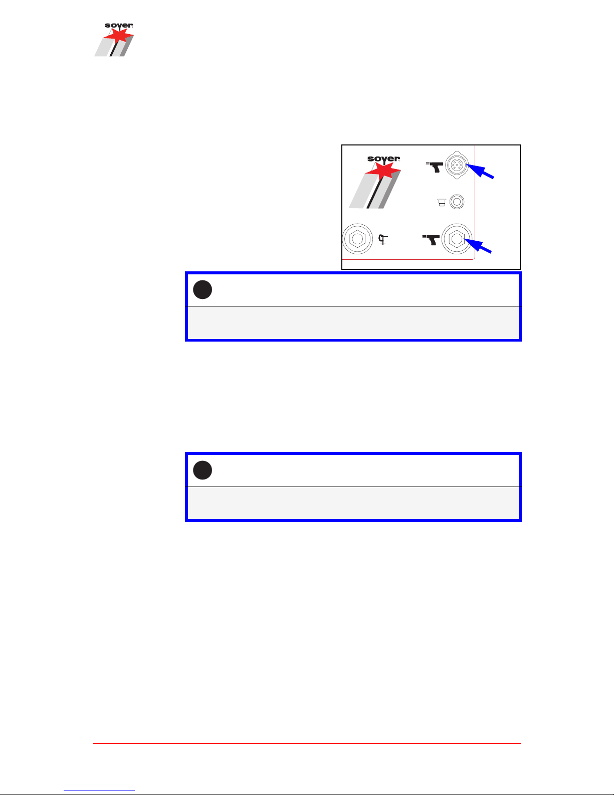
10.2.3 Connecting the stud welding gun
Only use the welding guns approved by the manufacturer. To do so, observe
Chapter "6.5 Permitted stud welding guns" on page 26.
Plug the welding cable into the
socket (a) and turn the plug to the
right up to the end stop.
Plug the control cable into the control cable socket (b) and tighten the
union nut.
10.2.4 Connecting the shielding gas supply
Prior to welding with shielding gas, a suitable gas supply must be established.
The gas connection on the back of the device is used for supplying gas to the stud
welding device via a pressure reducer (pressure reduction valve not included in
the scope of delivery).
i
Check whether the connection of the gun requires any special adapters
(see Chapter "6.5 Permitted stud welding guns" on page 26).
R
BMK-8i
www.soyer.com
a
b
i
The maximum permissible operating value for the shielding gas amount
is 12 l/min.

Setup and connection
44 Operating Manual Soyer Bolzenschweißtechnik
Example of a shielding gas cylinder with connection fittings (not included
in the scope of delivery).
Figure 6: Example of a gas supply
Item Designation
a Gas cylinder with shielding gas (for recommended mixtures, see
below)
b Main shut-off valve
c Pressure gauge for indicating the gas pressure in the gas cylinder
[bar]
d Gas flow rate meter [l/min] (pressure reduction valve)
e Shut-off valve for the gas connection hose of the stud welding device
f Gas connection hose of the stud welding device
g Valve for regulating the gas flow rate (maximum permissible gas
amount: 12 l/min)
a
b
d
c
e
g
f
Setup and connection
Operating Manual Soyer Bolzenschweißtechnik 45
Establishing the gas supply
Step 1: Check the gas cylinder, the connection fittings and the gas hose
with the connecting plugs for integrity and functionality.
Step 2: Connect the gas connection hose to the pressure reduction
valve of the gas cylinder and the stud welding device.
Step 3: Open the main valve of the gas cylinder and the shut-off valve of
the gas connection hose.
Step 4: Use the regulating valve to set a shielding gas flow rate of
approx. 4 - 5 l/min.
Step 5: Plug the shield gas hose of the gun into the stud welding device.
The gas supply is established.
BMK-8i
www.soyer.com

Setup and connection
46 Operating Manual Soyer Bolzenschweißtechnik
WARNINGWARNING
!
Danger from escaping gas
Numerous dangers can occur due to escaping gas, such as oxygen deprivation or line/gas cylinder whipping around.
• Make sure the gas cylinder is adequately secured against falling over and
damage.
• Make sure the gas cylinder, fittings and lines are always in a good condition.
• Make sure there is an adequate supply of fresh air when using, storing or
transporting the gas cylinder.
• Comply with the instructions of the gas/gas cylinder manufacturer.
• Carry out all necessary, prescribed checks of the gas cylinder, fittings and
lines.
• Safeguard the gas supply against unauthorised access.
i
The following shielding gas mixtures are recommended:
• 82% argon and 18% CO2 (preferred)
• 90% argon and 10% CO2
• 85% argon and 15% CO2

Settings
Operating Manual Soyer Bolzenschweißtechnik 47
11. Settings
The stud welding device and gun must be matched and adjusted for the respective processing.
11.1 Setting the welding parameters
How to set the welding parameters of the
• welding current
• welding time
•SRM current
• gas preflow time and
• lift time/height of lift
is explained in the following.
To achieve an optimum stud welding result, it is necessary to carry o ut some s ample welds with different settings.
The parameters to be set on the stud welding device also depend on the following
influencing factors:
• Material of the workpiece
• Thickness of the workpiece
• Material of the welding stud
• Diameter of the welding stud
11.1.1 Help tables for device setting
The values given in the following table can be useful as guide values for an initial
sample weld.
How the respective settings are made is explained in later chapters.
Settings
48 Operating Manual Soyer Bolzenschweißtechnik
The values were determined using a 2 mm thick plate.
The values were determined using a 2 mm thick plate.
BMK-8i SRM welding parameters setting aid
PH-9 SRM12 gun
Stud material Steel 4.8 A2-50 Steel 5.8 Steel 8.8 A2-50
Stud thread - type M6-MF M6-MF M8-HZ-1 M8-HZ-1 M8-HZ-1
General welding parameters
Welding current, approx.
[A]
200 200 270 270 270
Welding time, approx.
[ms]
250 250 300 300 300
SRM current, approx. [A] 0.30 0.30 0.30 0.30 0.50
Gas preflow time, approx.
[s]
1.0 1.0 1.0 1.0 1.0
Lift time/Height of lift
Required height of lift approx.: 1 - 1.5 mm
Lift time, approx. [ms] 13.5 13.5 13.5 13.5 13.5
BMK-8i SRM welding parameters setting aid
PH-3N SRM gun
Stud material Steel 4.8 A2-50 Steel 5.8 Steel 8.8 A2-50
Stud thread - type M6-MF M6-MF M8-HZ-1 M8-HZ-1 M8-HZ-1
General welding parameters
Welding current, approx.
[A]
200 200 270 270 270
Welding time, approx.
[ms]
250 250 250 250 250
SRM current [A] 0.20 0.20 0.30 0.30 0.50
Gas preflow time [s] 1.0 1.0 1.0 1.0 1.0
Lift time/Height of lift
Required height of lift, approx.: 1 - 1.5 mm
Lift time, approx. [ms] 12.5 10.0 8.5 8.5 8.5

Settings
Operating Manual Soyer Bolzenschweißtechnik 49
11.1.2 Setting the welding current and the welding time
If you do not have specified values, the table in Chapter "11.1.1 Help tables for
device setting" on page 47 can be used as an aid for a basic setting.
Setting the welding current and the welding time
Step 1: Connect the device as described in Chapter "10.2 Connection of
the stud welding device and the stud welding guns" on page 42.
Step 2:
Use the ↑↓ arrow keys to
select the position for the
welding current setting.
The LED lights up if the selection is correct.
Step 3: Use the +/- keys to set the
required value for the welding
current on the display.
The welding current has been set.
Step 4: Use the ↑↓ arrow keys to
select the position for the
welding time setting.
The LED lights up if the selection is correct.
Step 5: Use the +/- keys to set the
required value for the welding
time on the display.
The welding time has been set.
+
[A]
[ms]
[A]
[s]
[ms]
GAS
SRM
>
>
>
>
+
SRM
GAS
+
[A]
[ms]
[A]
[s]
[ms]
GAS
SRM
>
>
>
>
+
SRM
GAS

Settings
50 Operating Manual Soyer Bolzenschweißtechnik
11.1.3 Setting/deactivating the SRM current
If you do not have specified values, the table in Chapter "11.1.1 Help tables for
device setting" on page 47 can be used as an aid for a basic setting.
If an SRM current value > 0 A is set, SRM is automatically activated during welding with the set current value. If the setting is 0 A, SRM is deactivated.
Setting/deactivating the SRM current
Step 1: Connect the device as described in Chapter "10.2 Connection of
the stud welding device and the stud welding guns" on page 42.
Step 2: Use the ↑↓ arrow keys to
select the position for the SRM
current setting.
The LED lights up if the selection is correct.
Step 3: Use the +/- keys to set the
required value for the SRM
current on the display.
The SRM current is
adjustable from 0 - 1500 mA
(display in A) in 50 mA steps
(0.05 A).
i
If the setting is "0", SRM is deactivated.
The SRM current has been set.
+
[A]
[ms]
[A]
[s]
[ms]
GAS
SRM
>
>
>
>
+
SRM
GAS

Settings
Operating Manual Soyer Bolzenschweißtechnik 51
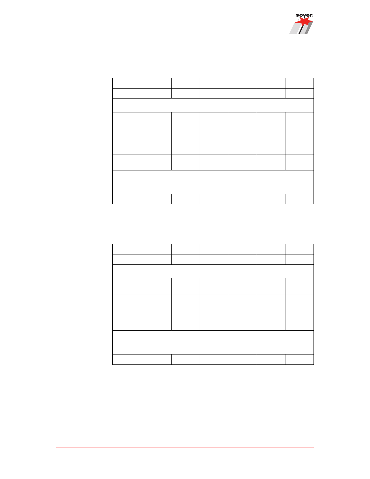
11.1.4 Setting the gas preflow time
If you do not have specified values, the table in Chapter "11.1.1 Help tables for
device setting" on page 47 can be used as an aid for a basic setting.
The "Gas test" mode can be used to check that the shielding gas flows through
the shielding gas cap of the gun. As soon as the release knob on the gun is
pressed, shielding gas flows out of the shielding gas cap of the gun for the time
set in seconds. This means the gas lines can also be purged with shielding gas
before starting work.
Setting the gas preflow time
Step 1: Connect the device as described in Chapter "10.2 Connection of
the stud welding device and the stud welding guns" on page 42.
Step 2: Use the ↑↓ arrow keys to
select the position for the gas
preflow time setting.
The LED lights up if the selection is correct.
Step 3: Use the +/- keys to set the
required value (1-5 s) for the
gas preflow time on the display.
The gas preflow time has been set.
+
[A]
[ms]
[A]
[s]
[ms]
GAS
SRM
>
>
>
>
+
SRM
GAS

Settings
52 Operating Manual Soyer Bolzenschweißtechnik
11.1.5 Setting the lift time (height of lift) in "Setup" mode
For drawn arc welding guns, the weld stud is lifted for a defined height/time just
before the welding process and automatically lowered again during the welding
process.
As the height of lift of the stud is difficult to measure, the equivalent lift time is
specified on the stud welding device.
In the following setting of the lift time, the welding process is simulated in "Setup"
mode. The lifting and lowering of the stud is the same as during welding, only the
welding current is not activated.
Operating modes
• Setup mode: No welding is carried out when simulating a welding process.
• Operating mode (normal mode): Welding is carried out
WARNINGWARNING
!
Danger from incorrect operating mode
If the following adjustment work is not carried out in "Setup" mode but in operating mode, pressing the trigger button on the gun causes a weld to be carried
out.
• Make sure that "Setup" mode is activated for the lift test.
Setting the lift time/height of lift with the stud welding device
Step 1: Connect the device as described in Chapter "10.2 Connection of
the stud welding device and the stud welding guns" on page 42.
Switch on the device.
Step 2: Fit the gun with a welding stud.
Step 3: Use the ↑↓ arrow keys to
select the position for the lift
test.
The LED lights up if the selection is correct.
+
[A]
[ms]
[A]
[s]
[ms]
GAS
SRM
>
>
>
>

Settings
Operating Manual Soyer Bolzenschweißtechnik 53
Notes on "Setup" mode
• The setup process can be repeated as often as required. However, to avoid
the magnetic coil overheating, maintain a waiting time of approx. one second
between two test strokes.
Step 4: Set the gun on the workpiece and
press the trigger button on the gun
for the weld.
Make sure the green "Stud on workpiece" control lamp lights up before
triggering.
The currently set value for the lift
time in [ms] appears on the display.
The longer the lift time, the higher
the height of lift. Determining the correct lift time requires experience and some trials. Guide values for the correct lift time can be
found in Chapter "11.1.1 Help tables for device setting" on
page 47.
The lift time is changed using the adjustment ring on the welding gun for the
height of lift of the stud.
Step 5: Make sure the device is in operating mode by selecting one of
the three functions above (green LEDs).
Setting the lift time/height of lift with the stud welding device
SRM
GAS

Welding operation
54 Operating Manual Soyer Bolzenschweißtechnik
12. Welding operation
How welds are carried out and how any weld defects can be avoided are described in the following.
12.1 Carrying out welding
How a weld is carried out with the stud welding gun is described in the following.
DANGER
!
Danger from incorrect operation
During stud welding, many hazards can arise if the devices are not operated
correctly.
• Before operating the stud welding device, observe Chapter "2. Important
safety instructions" on page 10.
• If you have any problems understanding the operating manual, please
contact the manufacturer, Soyer.
• Before each use, check that the devices and the lines with the plugs are
intact.
Carrying out welding
Step 1: Before welding, observe Chapter "2. Important safety instruc-
tions" on page 10.
Step 2: Connect the gun to the stud welding device (see Chapter "10.2
Connection of the stud welding device and the stud welding
guns" on page 42).
Pay attention to any necessary connection adapters.
Step 3: Insert the matching stud chuck and a welding stud (see Chapter
"7. Description of the SRM stud chuck" on page 28).
Only use Soyer welding studs.
Step 4: Check the welding parameters (see Chapter "11. Settings" on
page 47).

Welding operation
Operating Manual Soyer Bolzenschweißtechnik 55
Step 5: Make sure the device is in
operating mode by selecting
one of the three above functions.
Step 6: Check that the welding points on the stud and workpiece are
bare metal.
Step 7: Press the gun onto the workpiece at an angle of 90°.
If the contact to the workpiece and the earth connection are correct, the second LED from the top lights up.
Step 8: Press the gun trigger button.
Welding is carried out. During welding, the LED
for the trigger button and (when activated
accordingly) the LEDs for SRM welding and the
shielding gas also light briefly.
i
During the welding process, hold the gun still and only
pull the gun vertically away from the welded stud after
completing the welding process. This prevents the stud
chuck widening and becoming damaged.
The welding process is now complete.
Carrying out welding
+
[A]
[ms]
[A]
[s]
[ms]
GAS
SRM
>
>
>
>
SRM
GAS
SRM
GAS

Welding operation
56 Operating Manual Soyer Bolzenschweißtechnik
12.2 Notes on checking the quality of the weld
If the SOYER stud welding system is used properly and the correct materials are
chosen, the strength of the weld joint (weld zone) is always higher than that of the
stud or the basic material.
The following production weld tests have been proven in practice:
• Visual inspection
• Bend test
Further information is given in the standard:
DIN EN ISO 14555 Welding - Arc welding of metallic materials or in the DVS d ata
sheets DVS 0904 Instructions for practice - Arc stud welding.
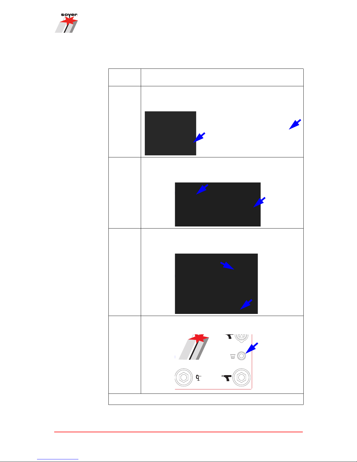
12.2.1 Visual inspection
Visual inspection is used for a rough check for major defects. The uniformity of
the weld is assessed here.
The following table serves as an aid for assessing a weld result.
Visual inspection
Welding image Note
Good weld joint.
Optimum setting.
Small weld bead, uniform, shiny and
closed.
Poor weld joint, e.g. due to excessive welding energy or immersion distance/lift too
low.
The stud is constricted at the weld joint. The
stud is only partly welded.
Poor weld joint, e.g. due to insufficient welding energy or immersion distance/lift too
low.
The weld bead is weak and unevenly
formed.

Welding operation
Operating Manual Soyer Bolzenschweißtechnik 57
12.3 Switching off the device
Switch off the stud welding device at the mains switch.
This also automatically switches off the connected welding gun.
Make sure that the stud welding device cannot be switched on and used by unauthorised persons.
Close the shut-off valves to the gas supply.
Poor weld joint, e.g. through arc blow out
effect, welding gun shaken or applied at a
slant.
The stud flange is not fully welded and has
visible defects. Undercuts are visible.
Visual inspection
Welding image Note

Welding operation
58 Operating Manual Soyer Bolzenschweißtechnik
12.4 Weld defects and their causes
The most common weld defects, their possible causes and how to troubleshoot
them are described in the following.
If the fault cannot be remedied as described, please contact Heinz Soyer Bolzenschweißtechnik GmbH.
Faults Possible cause and troubleshooting
The device cannot be
switched on.
• Check the mains supply fuses.
The device does not
weld, there is no (or
very little) spark formation.
The device is not connected to the mains or not switched on.
• Connect the device to the mains and switch it on. The LED displays light
up briefly when switching on.
The welding cable, control cable or gas hose are not correctly connected or
damaged.
• Connect the cables or gas hose correctly or examine for damage, replace
if necessary.
The connection plugs or sockets of the device are damaged.
• Have the plugs or sockets replaced by SOYER Customer Service.
Both earth cables are not (or not correctly) connected, or the earth clamps
are not fastened to the workpiece.
• Connect the earth cable, fasten the earth clamps to the workpiece.
The weld points or earth connection points on the workpiece are not bare
metal.
• Prepare the workpiece or studs.
The height of lift or the immersion depth is not set correctly.
• Set the height of lift or the immersion depth correctly in accordance with
the operating manual for the stud welding gun.
The gas flow rate is set too high, i.e. greater than 12 l/min (the arc is blown
out).
• Set the gas flow rate to a lower value.
The stud sits too loose in the stud chuck.
• Press the stud chuck together or reclamp.
Defect on the controller or on the welding gun.
• Notify SOYER Customer Service.

Welding operation
Operating Manual Soyer Bolzenschweißtechnik 59
The shielding gas
does not flow during
the welding process.
The gas cylinder is not (or is not correctly) connected to the device or the
valve, or the shut-off valve is not open.
• Connect the gas cylinder or open the valve or the shut-off valve.
The time for the gas preflow time is set to "0".
• Set the gas preflow time to the required preflow time.
The gas flow rate is set too low.
• Set the gas flow rate to 4 - 5 l/min with the regulating valve.
The solenoid valve in the device is soiled or defective.
• Contact Customer Service and have it replaced.
The stud does not lift,
there is no main current arc although the
"Stud on workpiece"
LED lights up.
The height of lift is not set correctly.
• Set the height of lift in accordance with operating manual for the stud
welding gun.
The controller of the device or the welding gun is defective. (The stud does
not lift despite correctly set height of lift).
• Notify SOYER Customer Service.
The stud lifts but the
main current is not
ignited.
The lift is too large.
• Set the lift in accordance with the operating manual for your welding gun.
The gas pressure is too high.
• Set the gas pressure to the specified value.
Faults Possible cause and troubleshooting

Welding operation
60 Operating Manual Soyer Bolzenschweißtechnik
Different weld results SRM current not set correctly
• Increase the SRM current parameter in steps and check if there is any
improvement.
Welding energy not set correctly.
• Adjust the welding energy.
Cable connections are too loose, there are transfer resistances.
• Check the proper seating of all cable connections and earth clamps.
Stud is too loose or not up to the end stop in the stud chuck.
• Press the stud up to the end stop, replace the stud chuck if necessary.
There is a magnetic arc blow out effect. The arc is pushed in a specific
direction
• Change the fastening of the earth clamps, place pieces of iron on the
edges or turn the welding gun.
The height of lift and/or the immersion depth are/is not set correctly.
• Set the height of lift and/or the immersion depth in accordance with the
operating manual for your welding gun.
Low quality studs with imprecise dimensions or poor surface quality have
been used.
• Only use Soyer welding studs.
The welding time and/or the gas flow rate are/is not set correctly.
• Set the welding time and/or the gas flow rate again.
Basic material is not suitable for welding.
• Use suitable material combinations.
One-sided beads are
formed at the same
points.
The formation of a bead is caused by magnetic arc blow out effect.The arc
is pushed in a specific direction
• Change the fastening of the earth clamps, place pieces of iron on the
edges or turn the welding gun.
The SRM current is set to 0 or is set too low.
• Increase the SRM current parameter in steps and check if there is any
improvement.
Very heavy spark formation,
stud flange almost
melted away.
Main current duration set too long.
• Re-adjust the time for the main current duration according to the table.
Welding current set too high.
• Re-adjust the welding current.
Faults Possible cause and troubleshooting

Welding operation
Operating Manual Soyer Bolzenschweißtechnik 61
Stud does not weld
with the entire flange
area, the strength of
the weld insufficient.
Main current duration set too short.
• Re-adjust the time for the main current duration according to the table.
Faulty earth connection.
• Check proper seating of the earth cable and earth clamps, tighten if necessary.
Excessive soiling of the workpiece surface.
• Clean the workpiece surface.
Front surface of the welding stud deformed.
• Use a new welding stud.
Stud protrusion beyond the stud chuck not set correctly.
• Set the distance between the stud chuck and the end of the weld stud to
3 - 5 mm.
Welding gun applied at a slant.
• Press the gun onto the workpiece at an angle of 90°.
Lift not set correctly.
• Adjust the lift.
The device switches
itself off.
The stud lift is not set correctly.
• Set the stud lift in accordance with the operating manual for the welding
gun and switch on the device.
The welding gun has been pulled off the workpiece during the main current.
• Switch the device back on.
The arc breaks off because the gas pressure is too high.
• Set the gas pressure to the specified value.
The surface of the workpiece has poor electrical conductance – the arc
breaks off.
• Grind off the surface.
Faulty mains supply.
• Check the mains supply fuses.
Fuse in the device defective
• Notify Customer Service.
Stud thread is burned. The stud chuck is worn out.
• Replace the stud chuck.
Faults Possible cause and troubleshooting

Maintenance and repair
62 Operating Manual Soyer Bolzenschweißtechnik
13. Maintenance and repair
The stud welding device and the stud welding guns must only be maintained and
repaired by Heinz Soyer Schweißtechnik GmbH or its authorised specialists.
14. Service
In the event of service, please contact:
Heinz Soyer Bolzenschweißtechnik GmbH
Inninger Straße 14
82237 Wörthsee
Tel.: 0049-8153-885-0
Fax: 0049-8153-8030
Mail: info@soyer.de
Please have the serial number at hand during service requests.
Alternatively, you can contact your respective Soyer representative. The contact
data is available on our web site at
www.soyer.de or
www.soyer.com (English)
15. Warranty conditions
The warranty period for commercial use or corresponding use is 12 months. In
the event of repair, we guarantee the elimination of deficiencies at the Etterschlag
factory. Wear parts are excluded.
The warranty claim expires if damage occurs through improper operation, repairs
or interventions by unauthorised persons as well as due to the use of accessories
and spare parts not intended on our system.
If third party welding studs are used, we accept no responsibility for the proper
functioning of the stud welder and the quality of the weld joint.

Warranty conditions
Operating Manual Soyer Bolzenschweißtechnik 63

Heinz Soyer Bolzenschweißtechnik GmbH
Inninger Straße 14
82237 Wörthsee
Tel.: 0049-8153-885-0
Mail: info@soyer.de
www.soyer.com
www.srm-technology.de
 Loading...