

SOYAL
ACCESS CONTROL SYSTEM
Contents
1
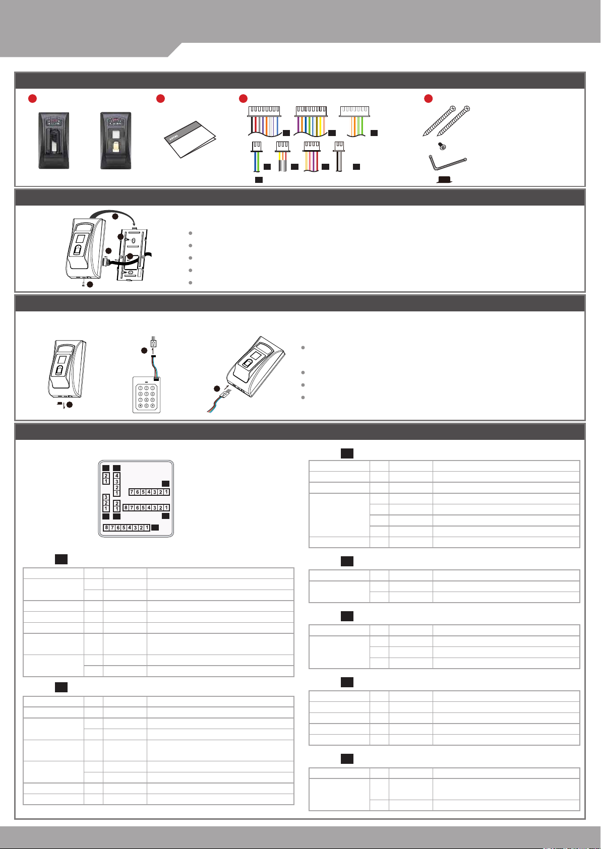
Product
or
AR- 881EFAR-881EV
Installation
4
®
2
User Guide
AR-881EF/AR-881EV
3
Terminal Cables
P1 P2 P3
P4 P5 P6 P7
P7
only provide to the controller that have doorbell function.
※
※
4
V110221
Tools
Flat Head Cap Philips
Tapping Screw: 4x38
Flat Head Hex Socket
Screw: M3x8
Security Torx Wrenches
Protection Plug
2
3
1
5
External WG keyboard
If you want to program system on controller directly, please order WG keyboard then install it according to the following pattern.
※
2
1
Connector Table
Pull the cables from the square hole of the mounting plate.
Use a screwdriver to screw the base onto the wall.
Connect the terminal cables to the body and attach the body to the mounting plate.
Assemble the covers with the Allen key and screws (accessories supplied).
Turn on the power and LED will light and beep will sound.
Remove the Protection plug that in the bottom left.
(※ Do not lose protection plug or it will affect the protection level.)
WG Keyboard cable will be connected to the pin board.
3
WG Keyboard connected to the controller from the bottom left of the hole.
When you nish programming system, please put protection plug back to the
controller.
P3Cable:
P6P4
P3
P7P5
P2
P1
Wire Application Wire Color Description
1 --- --2 --- --3
TCP/IP Output
Orange White
4 Orange
5 Green White
6 Gerrn
7 --- ---
Net - RXNet - RX+
Net - TXNet - TX+
P1Cable:
Wire Application Wire Color Description
Lock Relay
Common-COM-Point
Door Contact 4 Orange Negative Trigger Input
Exit Switch 5 Purple Negative Trigger Input
Alarm Relay 6 Gray
Power
1 Blue White (N.O.)DC24V1Amp
Purple White
2
3 White (COM)DC24V1Amp
7 Thick Red DC 12V
8 Thick Black DC 0V
(N.C.)DC24V1Amp
Transistor Output Max. 12V/100mA
(Open Collector Active Low)
P2Cable:
Wire Application Wire Color Description
Beeper 1 Pink Beeper Output
LED
Door Output 4 Blue White
Wiegand
WG Door
WG Exit Switch 8 Purple Negative Trigger Input
Contact
2 Yellow Red LED Output
3 Brown Green LED Output
Transistor Output Max. 12V/100mA
(Open Collector Active Low)
5 Thin Green Wiegand DAT: 0 Input
6 Thin Blue Wiegand DAT: 1 Input
7 Orange Negative Trigger Input
5V/100mA, Low
5V/20mA, Max
5V/20mA, Max
P4Cable:
Wire Application Wire Color Description
RS-485 for Lift
Controller
1 Thick Green RS-485(B-)
2 Thick Blue RS-485(A+)
P5Cable:
Wire Application Wire Color Description
Anti-Tamper
Switch
1 Red N.C.
2 Orange COM
3 Yellow N.O.
P6Cable:
Wire Application Wire Color Description
Power 1 Red DC 12V
Security trigger signal
Arming 3 Red White Arming Output
Duress 4 Yellow White Duress Output
P7Cable:
Wire Application Wire Color Description
Doorbell
2 Purple Security trigger signal Output
For the controller that doorbell function.
(
1 Black White
2
Black GND
Transistor Output Max. 12V/100mA
(Open Collector Active Low)
Output
)
Notice
Biometrics Device Access controller
Fingerprint & Finger Vein
V110221
1.Tubing:
2.Wire selection:
3.Power supply:
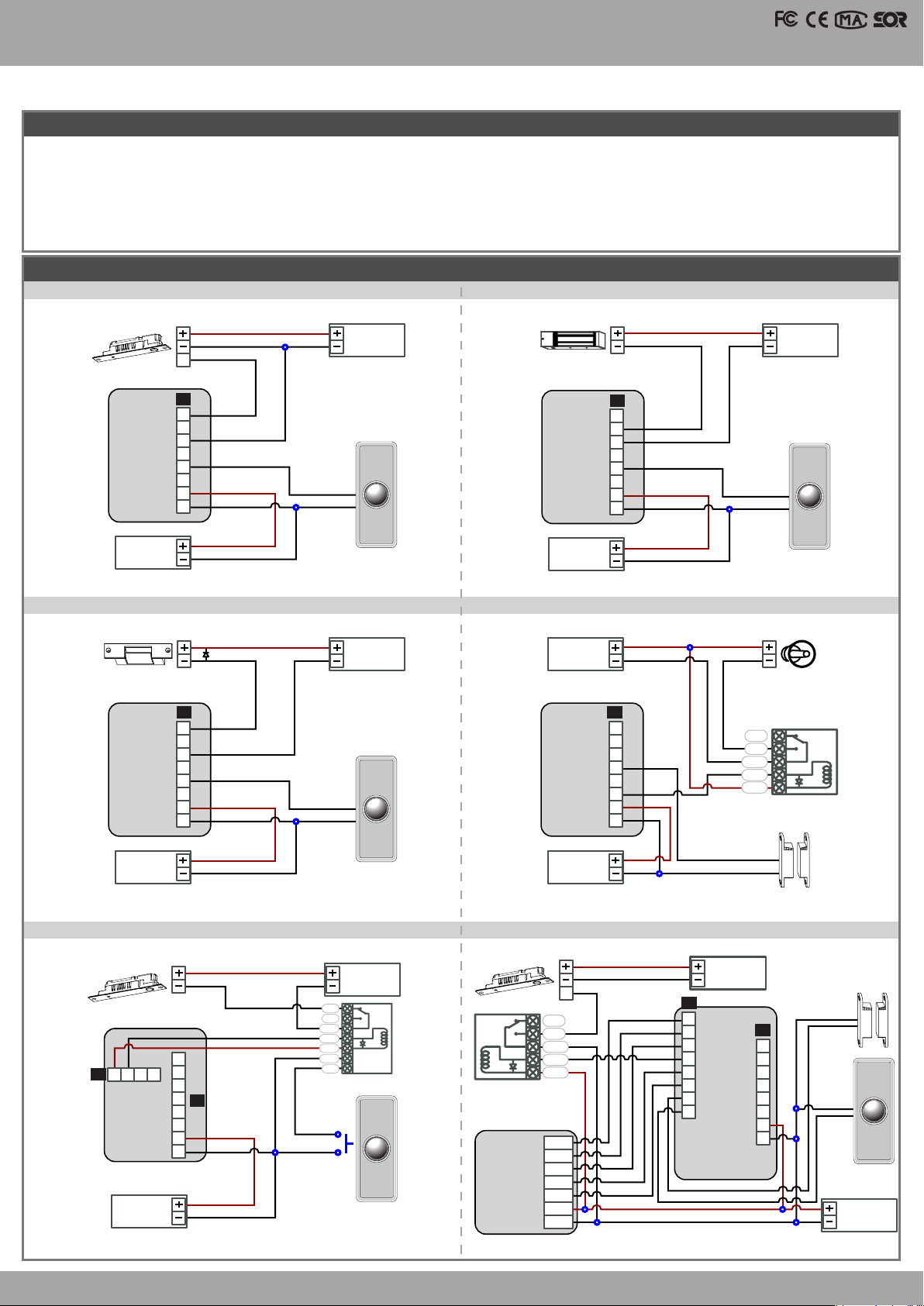
The communication wires and power line should NOT be bound in the same conduit or tubing.
Use AWG 22-24 Shielded Twist Pair to avoid star wiring.
Don’t equip controller and lock with the same power supply. The power for controller may be unstable when the lock is activating, that may make
the controller malfunction.
The standard installation: Door relay and lock use the same power supply, and controller use independent power supply.
Wiring Diagram
AR- 321H
Connect to Electric Bolt Connect to Magnet Lock
Electric Bolt
Controller
N.O.
COM
12V
GND
POWER
12VDC
PB
E
P1
1
2
3
4
5
6
7
8
12V
GND
Exit Switch
12V
GND
12V
GND
N.O.
GND
POWER
12VDC
EXIT
RTE
Controller
Magnet Lock
N.C.
COM
PB
12V
GND
POWER
12VDC
P1
1
2
3
4
5
6
7
8
12V
GND
12V
GND
12V
GND
POWER
12VDC
N.O.
GND
EXIT
RTE
Connect to Electric Strike
12V
GND
Electric Strike
1
N.O.
2
3
COM
4
5
PB
6
7
12V
8
Controller
GND
POWER
12VDC
12V
GND
Strengthen security with AR-721RB
12V
GND
Electric Bolt
1
2
4
1 2 3
P6
Controller
DDR
12V
POWER
12VDC
12V
GND
3
4
P1
5
6
7
8
12V
GND
12V
GND
12V
GND
N.O.
GND
N.C.
N.O.
COM
CTL
12V
GND
PB
AR-721RB
N.O.
POWER
12VDC
EXIT
RTE
POWER
12VDC
EXIT
RTE
Connect to Door Contact
ALM
12V
12V
GND
P1P1
1
2
3
4
5
6
7
8
12V
GND
Controller
POWER
12VDC
Door Contact
GND
POWER
12VDC
Connect to Reader
12V
GND
Exit Switch
E
N.C.
N.O.
COM
CTL
12V
BZ
RLED
GLED
Reader
WG 0
WG 1
12V
GND
POWER
12VDC
P2
BZ
1
RLED
2
GLED
3
Door Output
4
WG 0
5
WG 1
6
7
DS
8
PB
Controller
12V
GND
Alarm
N.C.
N.O.
COM
CTL
12V
Relay Outpot Module
N.C.
Door Contact
Door Contact
N.C.
P1
1
2
3
4
5
6
12V
7
GND
8
POWER
12VDC
EXIT
RTE

®
AR-881EF/AR-881EV
SOYAL
ACCESS CONTROL SYSTEM
Adding and Deleting Tag
Add Single Tag or Random tags
Input 123456 (or Master Code)
[e.g.] 2 readom cards with user addresses No. 100 and No. 101:
Access programming mode
Add the Sequential tags
Input 123456 (or Master Code)
[e.g.] User Address NO.101 to NO.120 have 20 pcs of sequential tags:(62312~62332)
Access programming mode
Delete a Single Tag
Input 123456 (or Master Code)
[e.g.] Delete User Address: 00058
Access programming mode
Delete a batch of Tags
Input 123456 (or Master Code)
[e.g.] Delete User Address: 00101~00245
Access programming mode
Delete All Tags
Input 123456 (or Master Code)
19 UUUUU 00001
→
19 00100 00001
→
19 UUUUU QQQQQ
→
19 00101 00120
→
10 SSSSS EEEEE
→
10 00058 00058
→
10 SSSSS EEEEE
→
10 00101 00245
→
29 29
→
Present the tag(s) with Controller
→
Present the tags one by one
→
→
Close Tag into RF Area
→
9
9
9
9
Present the tags
:
(only use th e tag NO.6 2312)
Tag Information
(single tag or random numbered cards one by one)
Done
→
(Present the tag with t he lowest number rst.)
OK
→
CARD CODE
SITE CODE
→
OK
CARD CODE
SITE CODE
V110221
Done
→
Programming
A. Entering and Exiting Programming Mode
Entering
Input 123456 or PPPPPP
[e.g.] The Default Value= 123456, if already changed the Master Code= 876112, input
Exiting
Input
Changing the Master Code
Access programming mode
[e.g.] If want to changing the Master Code= 876112, input
09 PPPPPPRRRRRR [Input the 6-digit new master code twice.]
→
123456
09 876112876112
→
87 6112
Access programming mode
→
B. Changing the Node ID of Reader
Access programming mode
[NNN= Node ID: 000 ~254; MMM=AR-881EF/EV Door NO.:1~255; AAA=WG Reader Door NO.:1~255
00 NNN MMM AA A
→
C. Anti-pass-back
Usually, anti-pass-back is commonly applied to parking areas in order to prevent from multi-entry with one card at a time, or somewhere wants to
monitor not only the access but also exit condition.
Enable device
Access programming mode
[e.g.] If the AR-881EF/EV set to exit reader, WG Reader set to access reader.
Access programming mode
Enable card user
Access programming mode
[e.g.] User address from 00152 to 00684 enable the anti-pass-back function: 26 00152 00684 0
20 U DDD U= Enable target unit(0=AR-881EF/EV,1=Reader) [Please refer to function default value for details.]
→
20 0 128
→
26 SSSSS EEEEE P
→
20 1 192 [Please refer to function default value for details.]
→
SSSSS= starting user address; EEEEE= ending user address [P=0 Enable/ P=1 Disable/ P=2 Reset]
D. Auto Open Zone
Door will keep opening after rst man ashing card. When the reader is stand-alone, suppor ting only 16 sets of auto-open zone by device setting.
Auto-open zone can extend up to unlimited sets by Networking.
Enable/Disable auto open zone
Access programming mode
[e.g.] If the AR-AR-881EF/EV set to Enable aut open zone.
Access programming mode
Enable/Disable auto open door without presenting card
Access programming mode
[e.g.] If the WG Reader set to Enable aut open door without presenting card.
Access programming mode
Setting up access time
Access programming mode
auto-open zone (NN=00~15); HHMMhhmm=Star ting time to ending time; 6543217H= 7 days of week + Holiday (F= 0: disable; 1: enable)]
[e.g.] AR-881EF/EV (without WG reader), to set second time zone which could be passed only at 9:30am to 4:20pm on Mon, Wed and Fri.
Access programming mode
20 U DDD U= Enable target unit(0=AR-881EF/EV,1=Reader) [Please refer to function default value for details.]
→
20 0 004 [Please refer to function default value for details.]
→
24 U DDD U= Enable target unit(0=AR-881EF/EV,1=Reader) [Please refer to function default value for details.]
→
24 1 128 [Please refer to function default value for details.]
→
08 MW NN HHMMhhmm 6543217H [M=AR-881EF/EV; W=Reader(0=disable,1=enable); NN: 16 sets of
→
08 10 02 09301620 01010100
→
setting is completed
→

Biometrics Device Access controller
Fingerprint & Finger Vein
E. Lift control
Connect with AR- 401RO16B to control oors which the user will be able to access. [BAUD9600]
Single oor
Access programming mode
UUUU=User Address LL=Floor number (01~64 oor)
[e.g.] User address NO. 45 only can reach the elevator to the 24th oor: 27 00045 24
Multi oors
Access programming mode
[UUUUU=User address G: 8 sets of lift control (Input: 0~7) LLLLLLLL:
8 oors setting (L=0=Disable, L=1=Enable)
[e.g.] User address NO. 168 can reach only the 6th and 20th oor:
Access programming mode
→ 21 00168 2 00001000
F. Setting Up the Arming
Conditions:
1. Arming is enabled
2.Alarm system connected
Enable Arming status:
Standby Mode
Card only
Enable all devices
Induct valid card → Input 4 digit
arming code
Enter Program Mode
Enable all devices: Access programming mode
Disable Arming status:
Standby Mode
Card only
Disable all devices
Induct valid card → Input 4 digit
arming code
Factory default armingcode is: 1234. U=Reader unit (0=AR-881EF/EV, 1=WG Reader).
※
→
→
9
G. Adding / Deleting Fingerprint or Finger-Vein
27 UUUUU LL
→
21 UUUUU G LLLLLLLL
→
21 00168 0 00100000
→
OK (Please refer to oor char t as right.)
→
Application:
1. Door open too long: Door is open longer than door relay time plus door close time.
2. Force open (Opened without a valid user card): Access by force or illegal procedure.
3. Door position abnormal: Arming is enabled and the power is suddenly off then on.
Enable particular device
Induct valid card → Input 4 digit
arming code → U
→
Disable particular device
Induct valid card → Input 4 digit
arming code → U
Card or Passcode
Input 5 digit user address → Input 4
digit pass code
arming code
Enable particular device: Access programming mode
Card or Passcode
Input 5 digit user address → Input 4
digit pass code
arming code
→ →
→
→ →
→
Please refer to below oor chart
Set
Floor
(G)
L
L
8
Input 4 digits
or U
Input 4 digits
9
or U
0
1
2
3
4
5
6
7
7
16
15
24
23
32
31
40
39
48
47
56
55
64
63
Card and Passcode
Induct valid card → Input 4 digit pass
code → → Input 4 digits arming
code
Card and Passcode
Induct valid card → Input 4 digit pass
code → → Input 4 digits arming
code
L
6
14
22
30
38
46
54
62
→
→
L
5
13
21
29
37
45
53
61
V110221
L
L
L
L
4
3
2
1
12
11
10
9
20
19
18
17
28
27
26
25
36
35
34
33
44
43
42
41
52
51
50
49
60
59
58
57
or U
→
9
or U
U
Adding
Access programming mode
[F=1= Adding 1 Finger data; F=2= Adding 2 Finger data; UUUUU=
How to add a nger data:
Adding
1 FingerVein
Adding
2 FingerVein
Adding
1 Fingerprint
(By DO)
Adding
2 Fingerprint
(By DO)
If you hear continuous "beep..." sounds when you place nger on the sensor, please release your nger from the sensor.
※
Deleting
Access programming mode
UUUUU=
Note:
※
1. For dual-ngerprint sensor module version, optical sensor module is the only enabled way for enrolling FP.
2. For dual-ngerprint sensor module version, user just can select one of the ngerprint sensor for identication and can´t put two ngerprint to
different sensor at the same time.
3. Extra WG keypad panel is needed for adding card or downloading data connected to PC.
4. Each nger
Finger
1
Finger
1
User address
need to be collected
(release)
(release)
Finger
93
→ Place your nger on the sensor
Bi
Bi
1
→ 0 UUUUU
F UUUUU
User address]
Finger
Finger
93
3 times
(Highe r)
Bi
(release)
1
(Highe r)
Bi
(release)
1
Finger
1
enrolling for AR-881EV / Each nger need to be collected
Finger
Finger
High pit ch
Long Bi
(OK)
1
1
(Highe r)
Bi
(release)
(Highe r)
Bi
(release)
Long Bi
(OK)
Deleting All
Access programming mode
Finger
2
Finger
(release)
2
High pit ch
Long Bi
(OK)
Bi
Finger
Bi
(release)
2
High pit ch
Long Bi
(OK)
93
→ 9 99999
1 times
enrolling for AR-881EF.
(Highe r)
Finger
High pit ch
Long Bi
2
(OK)
(Highe r)
Bi
(release)
High pit ch
Long Bi
(OK)

®
AR-881EF/AR-881EV
SOYAL
ACCESS CONTROL SYSTEM
Restoring Factory Settings
Reset all device parameters and user card data
Reset all device parameters and user card data:
Use the command:
Access programming mode
Use the Button on the PCB:
Press “IP Reset Button” of main board for few seconds. (Reference to the picture)
After operation as above, you will hear the reminder sound. And then please reopen the controller.
※
Restore factory default, the biometric identication system will stop using, please refer to [38 DDD ]
command to reopen.
Reset all user card data:
Access programming mode
Firmware Upgrade
→ 29
→ 29
Get the upgrade software from SOYAL or our distributor and run “UdpUpdater” software
29
29
9
V110221
Execute the soft ware
The software is within SOYAL CD or Login the
SOYAL web to downloads
Update the rmware
[Please login the SOYAL web to download the new ISP Firmware.]
1. Input the Target Address and Port
2. [Load Fide] open the documents that have the new ISP Firmware
3. Click the new ISP Firmware and [Open] it
4. Click [Update Device] to start the rmware update
5. Till the screen shown [Program Completed]
Front Panel & Indicator
Error
Processing
Left button Right button
OK
1
4
3
5
Indicator:
Left and right buttons can be used to select function
(for time attendance)
F1=Light=Duty on / F5=Flash=Break out
F2=Light=Duty off / F6=Flash=Break Return
F3=Light=Overtime on / F7=Flash=Go out
F4=Light=Overtime off / F8=Flash=Return
2
F1=Light=Duty on
F5=Flash=Break out
How to place nger for nger vein authentication unit
1. Set up the nger vein reader to the position where nger can easily be placed.
2. Use the middle or ring nger of either hand for the registration/authentication
purpose.
3. Put your nger tip rst to the top of the unit and lower the nger down along
the nger guide slowly.
The top of the unit
F2=Light=Duty off
F6=Flash=Break Return
F3=Light=Overtime on
F7=Flash=Go out
Use the middle or ring nger
(suggestion)
F4=Light=Overtime off
F8=Flash=Return
4. There is touch sensor on the rear end of the unit. Lower your nger
to touch the sensor to start verifying.
5. Red LED generates during the authentication.Please release the
nger when red LED turns off.
※Do not bend the nger to authenticate
※Do not press your nger on the recognition unit violently.
Lower the nger down along the nger
guide slowly.Release the nger when red
LED turns off.

Biometrics Device Access controller
IP Setting
Open your Web Browser and input factory default IP
address: http://192.168.1.127
If the IP address of AR-881EF/EV
has changed We must enter the
new IP address.
Page menu
Monitor the on-line computer
IP Setting
Change the Log-in information
Fingerprint & Finger Vein
V110221
Current State
Online Status is able to monitor and show which computer is linking on
Ethernet Module
Show which computer is li nking
on Ethernet Module.
Current IP address of the AR-881EF/EV
Log-in User Password
When you choose the "Networking Setting" or "User Password" at rst.
Log-in window will pop out and please input
At the Factory Default
※
User name: admin
Password: No as default value,so please just press “OK ” to log-in
Networking Setting
You will nd initial IP Address 192.168.1.127 and check
MAC Address is the same as sticker on Ethernet Module
device. Please revise IP address you want, and then click
“Update” button. After updating the IP, please re-connect
the Web Browser by new IP address.
admin
User Password
Change the log-in password to lock the IP setting of
Ethernet Module.
The password composes of 10 characters at most, it can be
either A~Z or 0~9.
寫入一 組新 的IP位置之後
Update
再按下
變更新的登入者密碼最多可設定
10
個字元
既可寫入新的IP位置
A~Z和0~9
來組合

SOYAL
ACCESS CONTROL SYSTEM
®
AR-881EF/AR-881EV
V110221
Command List (By WG Keyboard
)
Function Command Exposition
Entering programming mode PPPPPP
Exiting programming mode
Exiting programming mode and enabling all device
into arming status.
Enabling each device into arming status. U
Node ID setting 00 NNN MMM AAA
01 0 CCCCCCCCCCCC
IP Address assign (Must power reset)
01 1 255255255000
01 2 192168001254
Door relay time setting 02 U TTT
Alarm relay time setting 03 TTT
Arming delay
Alarm delay time setting 06 TTT
Master card setting 07 SSSSS EEEEE
Auto-open zone setting
Master code settings 09 PPPPPPRRRRRR
Suspend or delete tags
Recover tag
Setting up Card or PIN mode by user address 12 UUUUU PPPP
Arming output setting 14 TTT
Duress code setting 15 PPPP
Arming PWD setting 17 PPPP
Enabling or Disabling into arming status
Enabling or Disabling each device into arming status.
Enabling all device into arming status.
Disabling
Door open waiting time 18 TTT
Set the card by induction 19 UUUUU QQQQQ
Reader additional setting 20 U DDD
Lift control setting: multi-doors 21 UUUUU G LLLLLLLL
AR-401RO16/ AR- 401RO16B relay time setting 23 MMM TTT
Factory setting 24 U DDD
Real time clock setting 25 YYMMDDHHMMSS
time setting
all device into arming status.
05 TTT
MW NN
08
65 43217H
Suspend:10 SSSSS EEEEE
Delete
11 SSSSS EEEEE
Card+
Card+
Card+
Card+
10 SSSSS EEEEE
:
NNNN
NNNN U
NNNN
NNNN
HHMMhhmm
9
9
PPPPPP: Master Code, (Default value: 123456)
Including 881EF/EV, WG Reader
U=Enable target unit (0=881EF/ EV
NNN=Node ID,(001~254)
MMM=881EF/V Door Number,(001~255)
AA A=WG
default value =
CCCCCCCCCCCC = 192168001127
If set to 0 00.000.000.000 will enable DHCP otherwise
will disable DHCP
Netmask
Gateway assign
U=Enable target unit (0=881EF/EV , 1=WG Reader)
TTT=Door relay time
000 (Output constantly)
001~600=1-600 Sec.;601~609=0.1~0.9Sec.
TTT=Alarm relay time
001~600=1~600
Base on second, range: 001~255
Base on second, range: 001~255
SSSSS- EEEEE=00000~15999
SSSSS= starting user address; EEEEE= ending user address
M=881EF/EV; W=WG Reader (
NN=16 sets of auto-open zone (Range: 00~15)
HHMMhhmm=staring time to ending time
(e.g.: 08301200=08:30 to 12:00)
6543217: 7 days of week -Sat/Fri/Thu/Wed/Tue/Mon/Sun
(Input value: 0=disable; 1=enable)
H: Holiday (Input value: 0=disable; 1=enable)
PPPPPP= New master code
RRRRRR= Repeat the new master code
:Suspend :Delete
SSSSS= starting user address; EEEEE= ending user address
SSSSS= starting user address; EEEEE= ending user address
UUUUU= user address; PPPP=4-digit individual PWD
(Access mode: Card or PIN)
Base on 1ms, range:1~255, default value=10,
Input 0= Timeless
PPPP=4-digit PWD (0001-9999)
Default value:4321 ;disable PIN=0000)
PPPP
Default value:
NNNN:Arming PWD
U=Enable target unit (0=AR-881EF/EV , 1=WG Reader)
TTT=Doo r open wai ting time: 001~ 60 0=1~60 0 sec.;
default value: 15 sec.
UUUUU=user address
QQQQQ=Card quantity(00001=Continuously inducting)
U=Enable target unit (0=A
DDD=Function default value
UUUUU
LLLLLLLL=8 assigned oor (F=0: Disable, 1: Enable)
MMM=Node ID of lift controller
TTT= relay time: 000~600=1~600 sec.
U=Enable target unit (0=AR-881EF/EV , 1=WG Reader)
DDD:Function default value
YYMMDDHHmmSS: Year/Month/Day/Hour/Min./Sec.
Reader
Door Number,(001~255)
192.168.1.127
Sec.
9
=4-digit PWD (0001-9999)
1234
;disable PIN=0000)
R-881EF/EV , 1=WG Reader)
=user address;
G=4 sets of lift c ont rol(0~3);
1=WG Reader
,
0=disable; 1=enable
)
)

Biometrics Device Access controller
Fingerprint & Finger Vein
V110221
Command List (By WG Keyboard
)
Function Command Exposition
Anti-pass-back (Enable user) 26 SSSSS EEEEE P
Lift control setting: single door 27 UUUUU LL
Duress Function and Arming output setting 28 FFF
Delete all tag 29 29
Same tag reading interval time 31 TTTT Base on 10ms, range from 0 to 6000
Auto ring the clock alarm schedule 32 SS HHMMTT 6543217H
Holiday Setting 35 MMDD F
Enabling or Disabling into Full Access status 36 U E
RS485 port function setting
(Needs to be restarted after setting)
Biometric forms set
(Needs to be restarted after setting)
Adding / Deleting Fingerprint or Finger-Vein 39 F UUUUU
Deleting All Fingerprint or Finger-Vein 39 9 99999
Function Default Value
37 E
38 DDD
SSSSS= starting user address; EEEEE= ending user address
P=0=Enable; P=1=Disable; P=2=Initial
UUUUU
=user address;LL:
Arming output: FFF= 008 (default value)
Duress Function: FFF= 000
SS= 16 sets auto alarm schedule, range 0~15
HHMM= HH:MM (ex. 0830: Ring bell at 08:30)
TT=Period of time to ring bell
(Base on second, range 01~99 sec.)
6543217: 7 days of week -Sat/Fri/Thu/ Wed/Tue/Mon/Sun
(Input value: 0=disable; 1=enable)
H: Holiday (Input value: 0=disable; 1=enable)
MM= Month of year (01=Jan...10=Oct.)
DD= Date of month (01=1st day of month)
F= 0:Del; 1: Add
U=Enable target unit (0=AR-881EF/EV , 1=WG Reader)
E=1: Enable
E=0:AR401RO 9600
1:Host 9600
2:LED Panel 57600
3:Printer 115200
002=Finger-Vein recognition
004=Optical ngerprint recognition
008=Capacitive ngerprint recognition
012=Optical & Capacitive ngerprint recognition
F=1: Adding one nger data
2: Adding two nger data
0: Delete
UUUUU=user address
, 0:
Disable
Floor number(01~63 oor)
20 U DDD
Function Option Value Application
Time Attendance
Auto Re-lock
Auto Open
When Access Mode is "Card and PIN", Readers can skip pressing PIN code.※0: Disable 1: Enable 008 Networking/Stand-Alone
Exit by Push Button
Enable force Open
As Access/Exit Reader
Anti-pass-back
[e.g.] DDD value of AR-881EF to Enable "Auto Open" + "Exit by Push Button" + "Anti-pass-back" =004+016+128= 148
As a result of that, the command will be 20 0 148
0: Yes 1: No 001 Networking
※
0: Disable 1: Enable 002 Networking/Stand-Alone
※
0: Disable 1: Enable 004 Networking/Stand-Alone
※
0: Disable※1: Enable 016 Networking/Stand-Alone
0: Slave 1: Mater 032 Networking
※
0: Exit 1: Access 064 Networking
※
0: Disable 1: Enable 128 Networking
※
24 U DDD
Function Option Value Application
Reader and controller can control the same lock (only for reader)
Stop Alarm by...
Open door immediately without 1st card presented at auto open zone ※0: Disable 1: Enable 128 Networking/Stand-Alone
[e.g.] To enable two functions for WG reader. The DDD value will be "Control the same lock" + "Stop alarm by door closed" = 016 + 064 = 080
As a result of that, the command will be 24 1 080
※ U=Enable target unit (0=AR-881EF/EV , 1=WG Reader)
DDD:Function default value
0: Disable 1: Enable 016 Networking/Stand-Alone
※
0: None 1: Push button/Door Closed 064 Networking/Stand-Alone
※
Default Value
※
Default Value
※
http://www.soyal.com
SOYAL
Thanks for You
 Loading...