

Page 1
SOYAL
Copyright by SOYAL Technology Co., Ltd.. All rights reserved.
ACCESS CONTROL SYSTEM
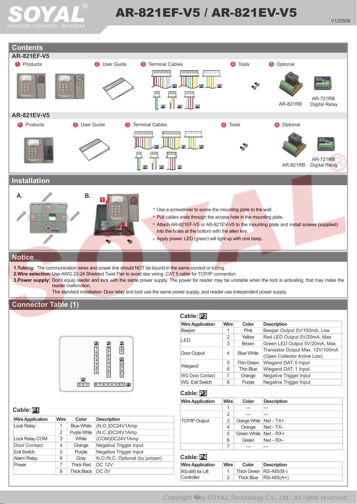
Contents
AR-821EF-V5
1
Products
®
2
User Guide
AR-821EF-V5 / AR-821EV-V5
3
Terminal Cables
P1 P2 P3
4
Tools
5
Optional
V120508
AR- 821EV-V5
1
Products
2
Installation
A. B.
Notice
1.Tubing:
2.Wire selection:
3.Power supply:
The communication wires and power line should NOT be bound in the same conduit or tubing.
Use AWG 22-24 Shielded Twist Pair to avoid star wiring ,CAT 5 cable for TCP/IP connection
Don’t equip reader and lock with the same power supply. The power for reader may be unstable when the lock is activating, that may make the
reader malfunction.
The standard installation: Door relay and lock use the same power supply, and reader use independent power supply.
User Guide
AR-721RB
3
Terminal Cables
P4 P5 P6
P1 P2 P3
AR-821RB
4
Tools
5
Optional
Digital Relay
AR-721RB
P4 P5 P6
AR-821RB
Digital Relay
1
Use a screwdriver to screw the mounting plate to the wall.
Pull cables ends through the access hole in the mounting plate.
2
Attach AR-821EF-V5 or AR-821EV-V5 to the mounting plate and install screws (supplied)
into the holes at the bottom with the allen key.
Apply power. LED (green) will light up with one beep.
Connector Table (1)
P3
P2
P4
8
2
1
7
6
P6
5
4
4
3
3
2
2
1
1
2
1
P1
Cable:
P1
P5
321
7
6
5
4
3
2
1
876 543
Wire Application Wire Color Description
Lock Relay 1 Blue White (N.O.)DC24V1Amp
2
Purple White
(N.C.)DC24V1Amp
Lock Relay COM 3 White (COM)DC24V1Amp
Door Contact 4 Orange Negative Trigger Input
Exit Switch 5 Purple Negative Trigger Input
Alarm Relay 6 Gray N.O./N.C. Optional (by jumper)
Power 7 Thick Red DC 12V
8 Thick Black DC 0V
Cable:
P2
Wire Application Wire Color Description
Beeper 1 Pink Beeper Output
LED
Door Output 4 Blue White
Wiegand
WG Door
Contact
2 Yellow Red LED Output
3 Brown Green LED Output
Transistor Output Max. 12V/100mA
(Open Collector Active Low)
5 Thin Green Wiegand DAT: 0 Input
6 Thin Blue Wiegand DAT: 1 Input
7 Orange Negative Trigger Input
5V/100mA, Low
5V/20mA, Max
WG Exit Switch 8 Purple Negative Trigger Input
Cable:
P3
Wire Application Wire Color Description
1 --- ---
2 --- ---
TCP/IP Output 3
Orange White
4 Orange
5 Green White
6 Green
Net - TX+
Net - TX-
Net - RX+
Net - RX-
7 --- ---
Cable: P4
Wire Application Wire Color Description
RS-485 for Lift
Controller
1 Thick Green RS-485(B-)
2 Thick Blue RS-485(A+)
5V/20mA, Max
Page 2
PW R
ER R
AR M
OK
PR E
V
5
SE RI ES
12/07
14 : 49 : 04
WED
Duty : 0
PW R
ER R
AR M
OK
PR E
V
5
SE RI ES
12
07
14 : 49 : 04
WED
Duty : 0
Biometrics Device Access controller
Copyright by SOYAL Technology Co., Ltd.. All rights reserved.
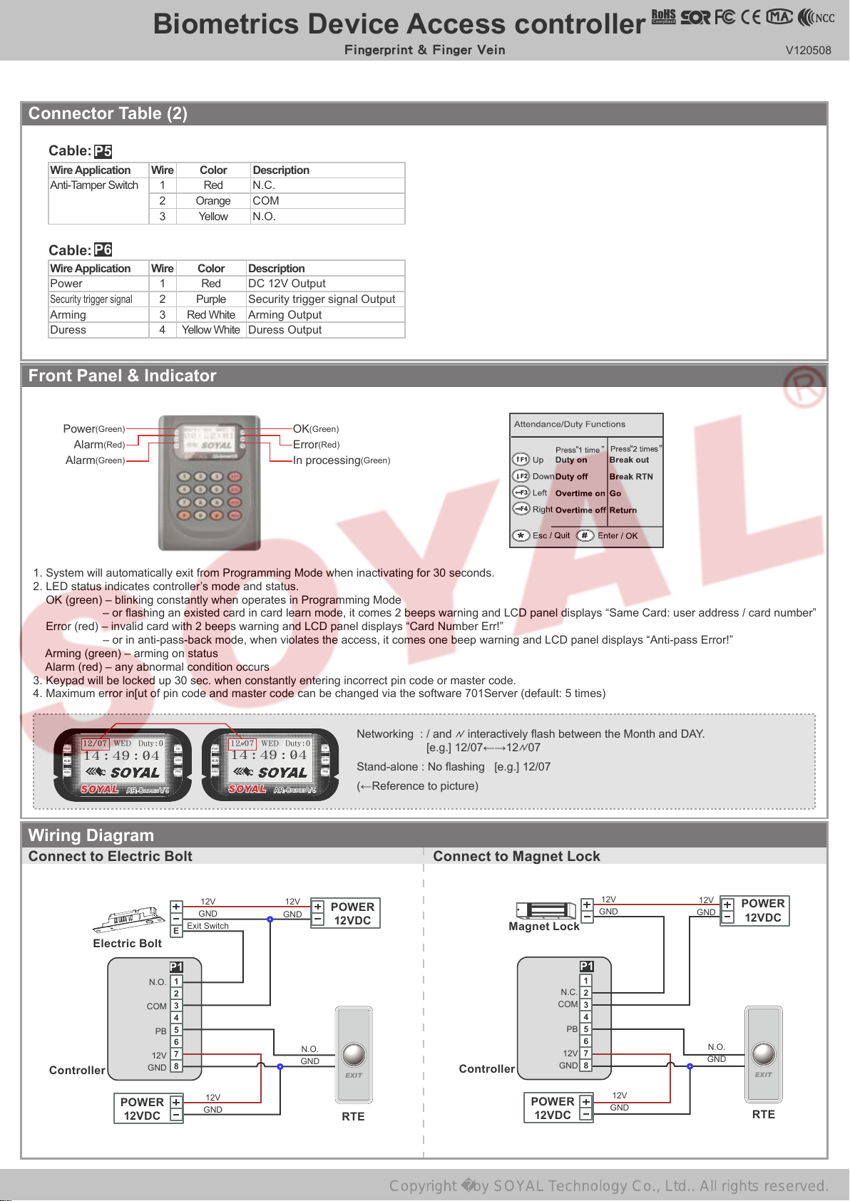
Connector Table (2)
Fingerprint & Finger Vein
V120508
Cable:
P5
Wire Application Wire Color Description
Anti-Tamper Switch 1 Red N.C.
2 Orange COM
3 Yellow N.O.
Cable:
P6
Wire Application Wire Color Description
Power 1 Red DC 12V
Security trigger signal
2 Purple Security trigger signal Output
Arming 3 Red White Arming Output
Duress 4 Yellow White Duress Output
Front Panel & Indicator
(Green)
Power
(Red)
Alarm
(Green)
Alarm
Output
(Green)
OK
Error
(Red)
In processing
(Green)
1. System will automatically exit from Programming Mode when inactivating for 30 seconds.
2. LED status indicates controller’s mode and status.
OK (green) – blinking constantly when operates in Programming Mode
– or ashing an existed card in card learn mode, it comes 2 beeps warning and LCD panel displays “Same Card: user address / card number”
Error (red) – invalid card with 2 beeps warning and LCD panel displays “Card Number Err!”
– or in anti-pass-back mode, when violates the access, it comes one beep warning and LCD panel displays “Anti-pass Error!”
Arming (green) – arming on status
Alarm (red) – any abnormal condition occurs
3. Keypad will be locked up 30 sec. when constantly entering incorrect pin code or master code.
4. Maximum error in[ut of pin code and master code can be changed via the software 701Server (default: 5 times)
Networking : / and interactively ash between the Month and DAY.
[e.g.] 12/07←→12 07
Stand-alone : No ashing [e.g.] 12/07
(←Reference to picture)
Wiring Diagram
Connect to Electric Bolt
E
12V
GND
Exit Switch
12V
GND
POWER
12VDC
Connect to Magnet Lock
Magnet Lock
12V
GND
12V
GND
POWER
12VDC
Electric Bolt
N.C.
COM
12V
GND
PB
P1
1
2
3
4
5
6
7
8
12V
GND
N.O.
GND
EXIT
RTE
Controller
POWER
N.O.
COM
GND
12VDC
PB
12V
P1
1
2
3
4
5
6
7
8
12V
GND
N.O.
GND
EXIT
RTE
Controller
POWER
12VDC
Page 3
®
Copyright by SOYAL Technology Co., Ltd.. All rights reserved.
AR-821EF-V5 / AR-821EV-V5
SOYAL
ACCESS CONTROL SYSTEM
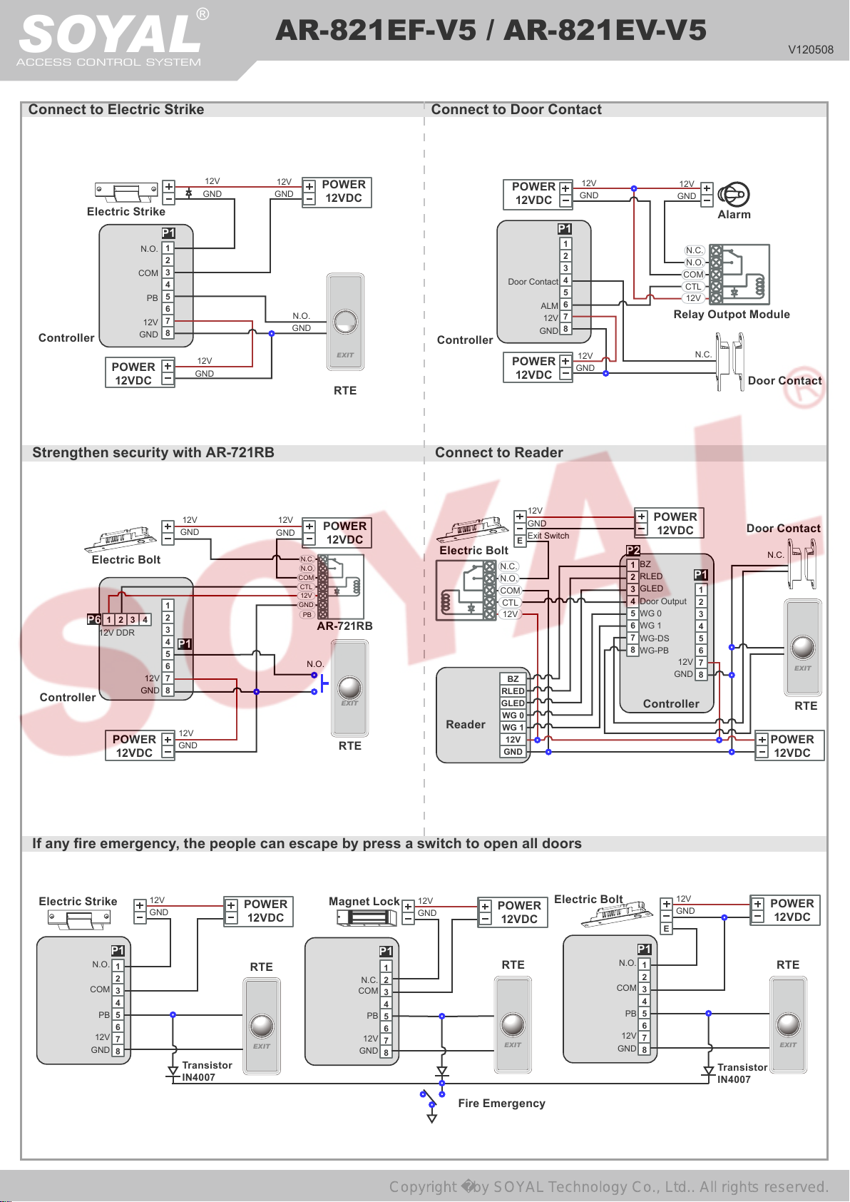
Connect to Electric Strike Connect to Door Contact
V120508
12V
GND
Electric Strike
P1
1
N.O.
2
3
COM
4
5
PB
6
7
12V
8
Controller
GND
POWER
12VDC
12V
GND
Strengthen security with AR-721RB
12V
GND
Electric Bolt
1
2
4
1 2 3
Controller
P6
DDR
12V
POWER
12VDC
12V
GND
3
4
P1
5
6
7
8
12V
GND
12V
GND
12V
GND
N.O.
GND
N.C.
N.O.
COM
CTL
12V
GND
PB
N.O.
POWER
12VDC
EXIT
RTE
POWER
12VDC
AR-721RB
EXIT
RTE
POWER
12VDC
Door Contact
ALM
12V
Controller
GND
POWER
12VDC
Connect to Reader
12V
GND
Exit Switch
Electric Bolt
Reader
E
N.C.
N.O.
COM
CTL
12V
BZ
RLED
GLED
WG 0
WG 1
12V
GND
P1
12V
GND
12V
GND
Alarm
1
2
3
4
5
6
7
8
12V
GND
N.C.
N.O.
COM
CTL
12V
Relay Outpot Module
N.C.
Door Contact
POWER
12VDC
P2
BZ
1
RLED
2
GLED
3
Door Output
4
WG 0
5
WG 1
6
7
WG-DS
8
WG-PB
Controller
12V
GND
P1
1
2
3
4
5
6
7
8
Door Contact
N.C.
EXIT
RTE
POWER
12VDC
If any re emergency, the people can escape by press a switch to open all doors
Electric Strike
N.O.
COM
PB
12V
GND
P1
12V
GND
POWER
12VDC
Magnet Lock
12V
GND
POWER
12VDC
P1
1
2
3
4
5
6
7
8
RTE
EXIT
Transistor
IN4007
N.C.
COM
PB
12V
GND
1
2
3
4
5
6
7
8
EXIT EXIT
Fire Emergency
Electric Bolt
N.O.
COM
PB
12V
GND
P1
12V
GND
E
1
2
3
4
5
6
7
8
POWER
12VDC
RTERTE
Transistor
IN4007
Page 4

Biometrics Device Access controller
Copyright by SOYAL Technology Co., Ltd.. All rights reserved.
Fingerprint & Finger Vein
Programming
A. Keyboard Lock/ Unlock
Lock/ Unlock
Press and , and at the same time to lock keyboard. Press again to unlock.
B. Entering and Exiting Programming Mode
Entering
Input 123456 or PPPPPP
[e.g.] The Default Value= 123456. If already changed the Master Code= 876112, input
P.S.If entering no instruction within 30 sec., it will automatically leave the programming mode.
Exiting
Press the repeatedly
Changing the Master Code
Access programming mode
C. Initial setup
Language Setting
Access programming mode
6
Quit or Quit and Arming (Please refer to alarm / arming setting)
→
5 2
Tool s
→
5 1 0
→
Tool s
7
→
→
Master Code
Language
Input the 6-digit new master code
→
EN → Succeeded → Initial system...
→
87 6112
Access programming mode
→
Succeeded
→
V120508
Node ID of Reader Setting
Access programming mode
WG1 Door Number : 0~255 → Show UID (0 =No,1=WG,2=ABA,3=HEX) → Enable DHCP(0:No,1:En,2=Exit) → Succeeded
→
3 1
Parameters[1]
→
→
Node ID
Input New Node ID : 1~254 (default value:001) → Main Door Number : 0~255
→
D. Adding and Deleting Tag
User capacity: 16384 (00000~16383)
※
Tag Information
CARD COD E
SITE COD E
Adding Tag by Tag ID
Access programming mode
Adding Tag by RF Learn Function
Access programming mode
Input Tag Units(pcs)
→
If a batch of tags are Sequential, input Tag Units(pcs) in the quantity of the tags and present the tag with
※
the lowest number to the controller.
Suspend User Address
Access programming mode
Suspend Tag by Tag ID
Access programming mode
Recover User Address
Access programming mode
CARD COD E
SITE COD E
1 1
Add/Delete
→
1 2
Add/Delete
→
Close Tag into RF Area
→
1 3
Add/Delete
→
1 4
Add/Delete
→
1 7
Add/Delete
→
Add -> Card ID
→
Add -> RF-Learn
→
Suspend -> Addr
→
Suspend -> ID #
→
Delete -> Addr
→
Input 5 -digit user address
→
Input 5 -digit user address
→
Input Start address
→
Input Site Code
→
Input Start address
→
→
Input End address
→
Input Card Code
→
Input End address
→
Input Site Code
Input Card Code
→
Recover Tag by Tag ID
Access programming mode
Deleteing User Address
Access programming mode
Deleteing Tag by Tag ID
Access programming mode
Setting up the access mode
Access programming mode
1 8
→
1 5
→
1 6
→
2 2
→
E. PIN Code
Access programming mode
Or via 701Client set it on Users screen
→
2
User Setting
Add/Delete
Add/Delete
Add/Delete
User Setting
Delete -> ID #
→
Delete -> Addr
→
Delete -> ID #
→
→
→
1
Access Mode
Password
→
Input Site Code
→
Input Start address
→
Input Site Code
→
Input User Address → 0: Invalid; 1: Card ; 2: Card or PIN; 3: Card & PIN
→
Input 5 -digit user address
Input Card Code
→
Input End address
→
Input Card Code
→
Input 4 -digit PIN (0001~9999)
→
Succeeded
→
Page 5

®
Copyright by SOYAL Technology Co., Ltd.. All rights reserved.
AR-821EF-V5 / AR-821EV-V5
SOYAL
ACCESS CONTROL SYSTEM
F. Adding / Deleting Fingerprint or Finger-Vein
Adding
Access programming mode
P.S. The AR- 821EF need to collect twice for each ngerprint, and the AR-821EV need to collect three times.
Deleting
Access programming mode
P.S. If you want to delete all users’ FP, key in 99999
G. Access Mode
Access programming mode
Access Mode
→
2
Key in 5-digit user address (00000~08999)
→
0:Invalid; 1:Card; 2: Card or PIN; 3: Card and PIN
→
Finger Identify: 0: Must ; 1: Ignore
→
Succeeded
→
2 6
User Setting
→
2 7
User Setting
→
2
User Setting
→
→
→
Enroll FP
Delete FP
#
Hardware 701Client Hardware 701Client
0:Invalid
1:Ca rd
2:Card or PIN
3:Card and PIN
Key in 5-digit user address →1 or 2 different ngers on the sensor lens → Succeeded
→
Key in 5-digit user address
→
Access Mode Finger Identif y Result
0: Must
1: Ignore
0: Must
1: Ignore
0: Must
1: Ignore
0: Must
1: Ignore
→
Succeeded
Just ngerprint
Just card control
Just ngerprint
Just card control
Just ngerprint
Just card control
Just ngerprint
Just card control
Just ngerprint
Just card control
Just ngerprint
Just card control
Just ngerprint
Just card control
Just ngerprint
Just card control
Invalid User
Finger+Card
1. Card Only
2. Finger Only
1. Finger+Card
2. Finger+PIN
3. Card+Finger+PIN
4. Card+Finger+Card
5. PIN+Finger+PIN
6. PIN+Finger+Card
1. Card Only
2. PIN Only
3. Finger Only
Finger+Card+PIN
1. Card+PIN
2. Finger+PIN
V120508
H. Arming Password
Access programming mode
Or via 701Server and set it on AR-829E screen
3
→
Parameters[1]
8
→
Arming PWD
Input 4 -digit PIN (0001~9999; Default: 1234)
→
Succeeded
→
I. Arming Delay Time
Access programming mode
Armed pulse out- put time. (10ms) ,Range:000~255
3
→
Par ameters[1]
7
ArmingDelayTm
→
→
Succeeded
Enter armed sta. Delay time(Sec) ,Range:000~255
→
;
J. Duress Code
Access programming mode
Or via 701Server to set it on AR-829E-V5 screen
Duress Code is only available in networking mode. It will substitute a personal pin code and send the message of Duress to computer as a
※
warning signal.
4 7
Parameters[2]
→
→
Duress Code
4 sets (select one)
→
Input 4 -digit PIN (0001~9999)
→
Succeeded
→
K. Terminal Port
Access programming mode
(default value:9600)
Succeeded
→
Tool s
→
5 4
→
Terminal Port
0:Lift ; 1:Host ; 2:LED ; 3:PRN (default value:1) → Baud Selection
→
L. Setting up the alarm / arming
Conditions:
1. Arming enabled
2.Alarm system connected
Application:
1. Door open too long: Door is open longer than door relay time plus door close time.
2. Force open (Opened without a valid user card): Access by force or illegal procedure.
3. Door position abnormal: When power is off and then on, reader on arming before power off.
Enable/Disable the arming status:
Standby Mode
Card only Card or PIN Card and PIN
Open the door
Present the tag to reader
4 digits arming PWD
Access Programming mode
Enable: Access programming mode
[Use FP] can substitute for [Induct valid card].
※
→
→
Input
No open the door
→
Present the tag to reader
→
7
→
Input 4 digits arming PWD
Quit & Arming
Input user address
digits individual PWD
Input 4 digits arming PWD
Disable: Access programming mode
Input 4
→
→ →
→
Present the tag to reader
4 digits individual PWD
Input 4 digits arming PWD
6
Quit
→
Input
→
→ →
→
Page 6

Biometrics Device Access controller
Copyright by SOYAL Technology Co., Ltd.. All rights reserved.
Fingerprint & Finger Vein
M. Anti-pass-back
While connect with AR-721U, AR-737H/U(WG mode) and AR-661U for anti-pass-back function, the access mode needs to be "Card" only.
Device enable
Access programming mode
Card user enable
Access programming mode
address
must select [1: Yes]
→
N. Lift control
[e.g.] Connect with AR- 401RO16B to control which oors the user will be able to access. (BAUD9600)
Setting Lift control
Access programming mode
Access programming mode
(need to use 725L485)
Set
Floor/ Stop
1
3
2
4
0
1
0
17
19
18
0
2
0
33
35
34
0
3
0
49
51
50
0
4
0
5
0
0
0
20
21
0
0
0
36
37
0
0
0
52
53
0
0
0
4 6
Parameters[2]
→
1 9
Add/ Delete
→
5 4
Tool s
→
5 5
Tool s
→
9
7
8
0
0
1
25
24
0
0
0
41
40
0
0
0
57
56
0
0
0
22
38
54
6
0
23
0
39
0
55
0
Terminal Port
→
Terminal Port
→
11
10
0
27
26
0
43
42
0
59
58
0
→
→
12
0
0
28
0
0
44
0
0
60
0
0
Anti-pass-back
Antipass Group
→ 0:
Lift Controller
→ 1:
13
14
15
30
46
62
16
0
0
1
31
32
0
0
0
47
48
0
0
0
63
64
0
0
0
0
29
0
45
0
61
0
master controller select [1: Yes] → WG select [1: Yes]
→
Input 5 -digit star ting user address
→
→
Lift Controller → Baud Selection 0: 9600
Input 5 -digit ending user
V120508
Single oor
Access programming mode
Input 5 -digit user address
2 4
User Setting
→
Input single oor number: 1~64
→
Multi oors
Access programming mode
→
2
User Setting
multi oors number [0:disable, 1: enable]
[e.g.] Set NO. 114, can use it with the 8 F and 16F:
Access programming mode
→
2
User Setting
O. Alarm Clock (for Factory)
Access programming mode
(Seconds as the bell time, Range:1~255)
Hardware installation
Music Box
Horn
5 9
→
Board
Tool s
→
Mike device
Mike device
Single Floor
→
5
Multi Floor
→
5
→
Daily Alarm
Set Weekday (0:disable, 1: enable) → Succeeded
→
→
→
Input 5 -digit user address
→
Multi Floor
→
114
→
1
→
Set (00~15) → Set Start Tm (24 Hours) ; Set Effect Sec.
POWER
12VDC
DC 12V Relay Board
12V
CTL
COM
N.O.
N.C.
Mike's sound wire
Mike's sound wire
M1
M2
GND
Music Box
Output to M1 and M2
Select range: 1 or 2 or 3 or 4
→
0000000100000001
P1
1
2
3
4
5
6
ALM
7
12V
8
GND
Controller
Input 16 digits
→
P. OpenZone
Access programming mode
Open Door Imm. During Open Zone (0 :No ,1:Yes)
Open Zone (0:No,1:Yes)
3 2
Parameters[1]
→
Succeeded
→
OnOff OpenZone
→
WG1 Port Auto Open Zone (0:disable,1:enable) → Open Door Imm. During
→
Q. Open TimeZone
Access programming mode
WG Port (0:disable, 1: enable) → Weekday (0:disable, 1: enable)
5 6
→
Tool s
Open TimeZone
→
Main Controller Auto Open Zone (0:disable,1:enable)
→
Set (00~15) → Time (24 Hours) ; Main Port (0:disable, 1: enable) ;
→
succeeded
→
→
Page 7

®
Copyright by SOYAL Technology Co., Ltd.. All rights reserved.
AR-821EF-V5 / AR-821EV-V5
SOYAL
ACCESS CONTROL SYSTEM
Firmware Upgrade
Get the upgrade software from SOYAL or our distributor and run “UdpUpdater” software
Execute the software The software is within SOYAL CD or Login the SOYAL web to downloads
V120508
2
1
5
Update the rmware
[Please login the SOYAL web to download the new ISP Firmware.]
1. Input the Target Address and Port
2. [Load F/W] open the documents that have the new ISP Firmware
3. Click the new ISP Firmware and [Open] it
4. Click [Update F/W] to start the rmware update
5. Till the screen shown [Firmware Update is Complete]
4
3
Restoring Factory Settings
Reset all device parameters and user card data
Reset all device parameters and user card data:
Access programming mode
1 : User Setting ; 2 : System & User
Reset IP Setting:
When the device's power is on, press the【RESET】button the main board untill the ERR (Red) LED of
screen lights up. (Reference to picture)
After operation as above, you will hear the long reminder sound,and wait until the sound
※
disappear then reset the power of the controller,the device will restore factory setting.
After done the "Factory Reset", the External Communication Port must be reset. Or the
※
biometric sensor won't be functional.
5
Tools → Ext. Comm Port (0:FP-200 ; 1:Lif t ; 2:Vein2000 ; 3:FP-9000 ; 4:Reserved )
Manu Tree
1. Add/ Delete
1. Add > Card ID
2. Add > RF Learn
3. Suspend > Address
4. Suspend > ID #
5. Delete > Address
6. Delete > ID #
7. Recover > Address
8. Recover > ID #
9. Antipass Group
5
2. User Setting
1. Password
2. Access Mode
3. Extend Options
4. Single Floor
5. Multi Floor
6. Enroll Finger
7. Delete Finger
→
Parameters2
Factory Reset →0 : System Param ;
→
94
3. Parameters[1]
1. Node ID
2. OnOff OpenZone
3. Door Relay Tm
4. Door Close Tm
5. Alarm Relay Tm
6. Alarm Delay Tm
7. Arming Delay Tm
8. Arming PWD
4. Parameters[2]
1. Auto Relock
2. Egress(R.T.E)
3. Miscellaneous
4. Force Open
5. Close & Stop
6. Anti-pass-back
7. Duress Code
8. Password Mode
9. Factory Reset
5. Tools
1. Language
2. Master Code
3. Master Range
4. Terminal Port
5. Ext.Comm Port
6. Open Time Zone
7. Informations
8. Clock Setting
9. Daily Alarm
RESET
6. Quit
7. Quit & Arming
Page 8

Biometrics Device Access controller
Copyright by SOYAL Technology Co., Ltd.. All rights reserved.
IP Setting
Open your Web Browser and input factory default IP
address: http://192.168.1.127
If the I P a ddress o f AR -821Ev 5
has changed We must enter the
new IP address.
Page menu
Monitor the on-line computer
IP Setting
Change the Log-in information
Current State
Online Status is able to monitor and
show which computer is linking on Ethernet Module
Fingerprint & Finger Vein
V120508
Show which computer is li nking
on Ethernet Module.
Current IP address of the AR-821Ev5
Log-in User Password
When you choose the "Networking Setting" or " User Password" at rst.
Log-in window will pop out and please input
At the Factory Default
※
User name: admin
Password: No as default value,so please just press “OK” to log-in
Networking Setting
You will nd initial IP Address 192.168.1.127 and check
MAC Address is the same as sticker on Ethernet Module
device. Please revise IP address you want, and then click
“Update” button. After updating the IP, please re-connect
the Web Browser by new IP address.
admin
User Password
Change the log-in password to lock the IP setting of
Ethernet Module.
The password composes of 10 characters at most, it can be
either A~Z or 0~9.
 Loading...