

Page 1
SOYAL
ACCESS CONTROL SYSTEM
Contents
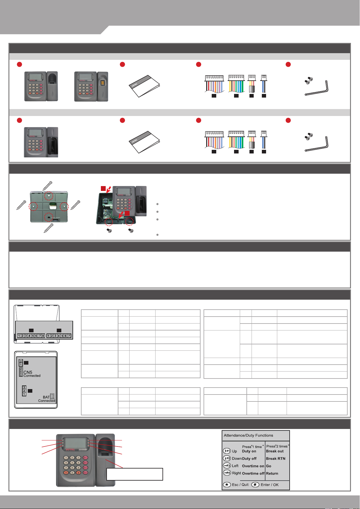
AR-821EF [Fingerprint]
1
Products
®
AR-821EF / AR-821EV
2
User Guide
3
Terminal Cables
4
Allen Key and Screws
V091028
or
DO MT
P1 P2 P3 P4
AR-821EV [Finger Vein]
1
Products
2
User Guide
3
Terminal Cables
P1 P2 P3 P4
4
Allen Key and Screws
Installation
A. B.
1
Use a screwdriver to screw the mounting plate to the wall.
2
Pull cables ends through the access hole in the mounting plate.
Attach AR-821EF or AR-821EV to the mounting plate and install screws (supplied) into the
holes at the bottom with the allen key (supplied).
Apply power. LED (green) will light up with one beep.
Notice
1. Tubing: The communication wires and power line should not be housed in the same electrical conduit or tubing.
They should always be installed in separate tubes.
2. Cable selection: Use AWG 22-24 “Shielded Twisted Pair” to avoid star wiring.
3. Power supply: Do not connect the reader and lock to the same power suppy. While the lock activates, it will cause the reader’s power to be unstable
and affect the readers operation. The standard connection of power supply is to have the door relay and the lock use one supply;
the reader uses an independent supply.
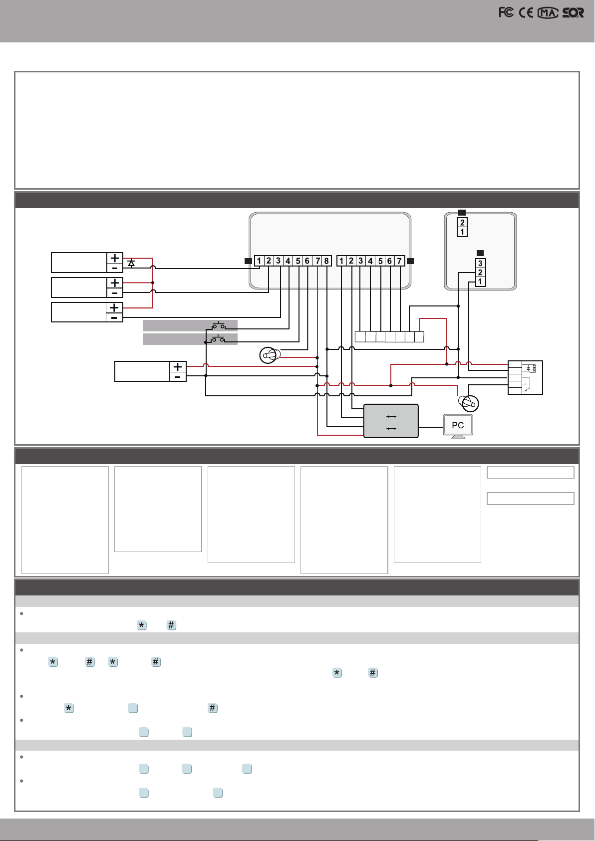
Connector Table
P1 P2
P4
P3
P1.
Wire Application
Door Relay
Common-COM-Point
Door Sensor
Exit Switch
Alarm Relay
Power
P3.
Wire Application
Tamper Switch
Wire
1
2
3
4
5
6
7
8
Wire
1
2
3
Color
Blue White
Purple White
White
Orange
Purple
Gray
Thick Red
Thick Black
Color
Red
Orange
Yellow
Description
(N.O.)DC24V1Amp
(N.C.)DC24V1Amp
(COM)DC24V1Amp
Negative Trigger Input
Negative Trigger Input
N.O./N.C. Optional
(by jumper)
DC 12V
DC 0V
Description
N.C.
COM
N.O.
P2.
Wire Application
Networking
Wiegand
Buzzer
LED
P4.
Wire Application
Serial Port
Wire
1
2
3
4
5
6
7
Wire
Color
Thick Green
Thick Blue
Blue
Green
Pink
Brown
Yellow
Color
1
Black
2
Blue
Description
RS-485 (B-)
RS-485 (A+)
WG DAT: 1 Inpu
ABA Clock Input
WG DAT: 0 Input
ABA Data Input
Buzzer Output 5V/100mA, MAX
LED Green Output 5V/20mA, MAX
LED Red Output 5V/20mA, MAX
Description
Signal Ground
TTL Serial Data Output in
4800, N, 8, 1
Front Panel & Indicator
(Green)
Power
(Red)
Busy
(Red)
Alarm
Card Present/ Arming
(Green)
OK
(Red)
Error
Fingerprint or Finger-Vein
Scan Area
(Green)
Page 2
LCD Access Controller
Fingerprint & Finger Vein
1. System will automatically exit from Programming Mode when inactivating for 30 seconds.
2. LED status indicates controller’s mode and status.
Busy (red) – blinking constantly when operates in Programming Mode
– or ashing an existed card in card learn mode, it comes 2 beeps warning and LCD panel displays “Same Card: user address / card number”
Error (red) – invalid card with 2 beeps warning and LCD panel displays “Card Number Err!”
– or in anti-pass-back mode, when violates the access, it comes one beep warning and LCD panel displays “Anti-pass Error!”
Arming (green) – arming on status
Alarm (red) – any abnormal condition occurs
3. Keypad will be locked up when constantly entering incorrect pin code or master code.
4. Maximum error times of pin code and master code can be changed via the software 701Server (default: 3 times)
Diagram
P4
TTL
GND
N.O.
N.C.
COM
Strike Lock
Bolt Lock
(Magnet Lock)
Door SENPBALMV+V-
P1 P2
B-A+WG0
Blue
Thick Blue
Thick Green
WG1BZGLED
Pink
Green
Brown
RLED
Yellow
P3
N.O.
COM
N.C.
V091028
Lock Power
Magnetic Door Contacts
Push Button
N.C.
N.O.
V-
+12V
Power
Manu Tree
1. Add/ Delete
1. Add > Card ID
2. Add > RF Learn
3. Suspend > Address
4. Suspend > ID #
5. Delete > Address
6. Delete > ID #
7. Recover > Address
8. Recover > ID #
9. Antipass Group
Programming
2. User Setting
1. Password
2. Access Mode
3. Extend Options
4. Single Floor
5. Multi Floor
6. Enroll FP
7. Delete FP
3. Parameters[1]
1. Node ID
2. Auto open Zone
3. Door Relay Tm
4. Door Close Tm
5. Alarm Relay Tm
6. Alarm Delay Tm
7. Arming Delay Tm
8. Arming PWD
4. Parameters[2]
1. Auto Relock
2. Egress(R.T.E)
3. Attendance
4. Master Node
5. Force Open
6. Close & Stop
7. Anti-pass-back
8. Duress Code
9. Check User FP
A. Keyboard Lock/ Unlock
Lock/ Unlock
At the same time according to and keyboard can be locked, and then press once to unlock.
B. Entering and Exiting Programming Mode
Entering
Input 123456 or PPPPPP
[i.e.] The Default Value= 123456. If already changed the Master Code= 876112, input
87 6112
P.S.If within 30 sec. entering no instruction, it will automatically leave the programming mode.
Exiting
Press the repeatedly
→
6
Quit
then press to conrm
→
Changing the Master Code
Access programming mode
5 2
Tool s
→
→
Master Code
Input the 6-digit new master code
→
C. Initial setup
Changing the Language
Access programming mode
Changing the Node ID of Reader
Access programming mode
in which format? (1.No, 2.WG, 3.ABA, 4.HEX) → Succeeded
5 1 1
Tool s
→
3 1
Parameters[1]
→
→
Language
→
EN → Succeeded → Initial system...
→
Node ID
Input New Node ID:1~254(default value: 001) → Input: 1~4 to Show Card ID
→
WG1
BZ
WG0
A+
Converter
B-
RS-485 RS-232
V-
RS-485 USB
V+
→
→
LEDGRLED
V- V+
RED
V-
+12V
or
RS-232
USB
5. Tools
1. Language
2. Master Code
3. Master Range
4. Terminal Port
5. AR401RO16 Node
6. Open Time Zone
7. Informations
8. Clock Setting
Access programming mode
Succeeded
12V
CTL
COM
N.O
N.C
6. Quit
7. Quit & Arming
Page 3

®
AR-821EF / AR-821EV
SOYAL
ACCESS CONTROL SYSTEM
D. Adding / Deleting Fingerprint or Finger-Vein
Adding
Access programming mode
P.S. The AR-821EF need to collect twice, and the AR-821EV need to collect three times.
Deleting
Access programming mode
P.S. If you want to delete all users’ FP, key in 9999
E. Access Mode
Access programming mode
Check FP Image: 1: Yes; 2: No → Succeeded
Access Mode
1: FP/Tag
2: or PIN
3: and PIN
4: Pause
4 9
Parameters[2] → Check User FP → must select [1: Yes]
※
F. PIN Code
Access programming mode
Or via 701Client to set it on Users screen
G. Arming Password
Access programming mode
Or via 701Server to set it on AR-821EF or AR-821EV screen
H. Duress Code
Access programming mode
Or via 701Server to set it on AR-821EF or AR-821EV screen
Duress Code is only available in networking mode. It will substitute a personal pin code and send the message of Duress to computer as a warning
※
signal and access door.
I. Setting up the alarm
Conditions:
1. Arming enabled
2.Alarm system connected
Application:
1. Door opened too long (After Normal Opening): The Door is Opened over the time of door relay time and door close time.
2. Door sensor error: Door sensor is open loop.
3. Force open (Opened without a valid user card being showed): Access by force and illegal procedure.
Flow char t:
A.Normal Opening:
2 6
User Setting
→
2 7
User Setting
→
2
User Setting
→
User Access Type
[Check FP Image] must select [1: Yes]
FP only/ Tag + FP
FP only/ Tag + FP/ PIN + FP
FP + PIN
Pause
2
User Setting
→
3
Parameters[1]
→
4
Parameters[2]
→
Enroll FP
→
Delete FP
→
#
Access Mode
→
2
Password
→
1
→
8
→
8
Door Op ened
Arming PWD
Duress Code
Key in 5-digit user address
→
Key in 5-digit user address
→
Key in 5-digit user address
→
[Check FP Image] must select [2: NO]
FP only/ Tag only
FP only/ Tag only/ PIN only
FP + PIN/ Tag + PIN
Pause
Key in 5-digit user address
→
Key in 4-digit PIN (0001~9999; Default: 1234)
→
4 sets (select one)
→
→
→
→
2 different ngers on the sensor lens → Succeeded
Succeeded
1:FP/Tag; 2:or PIN; 3: and PIN; 4: Pause
→
Key in 4-digit PIN (0001~9999)
→
Succeeded
→
Key in 4-digit PIN (0001~9999)
Alarm s ystem activat ed
→
Succeeded
→
→
Succeeded
V091028
Enable Arming Arming Delay TM
Arming settingArming setting Alarm triggerAlarm triggerDoor open durationDoor open duration
B.Abnormal Opening:
Enable Arming Arming Delay TM
Arming settingArming settingAlarm triggerAlarm trigger
Function
Door Relay TM
Door Close TM
Alarm Relay TM
Alarm Delay TM
Arming Delay TM
Command Description
1
2
4
3
3
3
3
4
3
2
1
5
3
6
3
7
Door Relay TM
1 Door Close TM2 Alarm Delay TM3 Alarm Relay TM4
Alarm s ystem activat ed
Alarm Delay TM
1 Alarm Relay TM2
To set how long the door relay (lock release) is active after showing a card.
Range: 0 ~ 600 (sec.); 601~609 (0.1~0.9 second). To set value “0” will make door keep opening til the card is
presented again, and then door close. (Default value: 7 sec.)
Setting how long the door can remain open before activating the alarm.
(Based on second, range: 000~255, default value: 15 sec.)
When an alarm condition has arisen, the alarm will activate for this duration. Range: 1 ~ 600 (sec.)
To set value “0” will make alarm relay keep on until disarming, then alarm relay off. (Default value: 7 sec.)
To delay the activation of the alarm relay after an alarm condition has arisen, so that user can have enough time
to disable alarm. (Based on second, range: 000 ~255, dfault value: 1 sec.)
To delay the time of enabling arming, so that user can have enough time to disable arming.
(Based on second, range: 000~255, default value: 1 sec.)
Page 4

LCD Access Controller
Fingerprint & Finger Vein
J. Anti-pass-back
Access mode Card and Pin, Card Pin or Card only for the model AR-721K
Access mode Card only for the model AR-721U, AR-737H/U (WG mode) and AR-661U
Device enable
Access programming mode
Card user enable
Access programming mode
address
Software Settings on 701Server
select [1: Yes]
→
1. Click “82X” icon
2. Click “Read From Controller”
3. Click “Write To Controller” once setting completed
4. Click “Exit”
4 7
Parameters[2]
→
1 9
Add/ Delete
→
→
Antipass Group
→
Anti-pass-back
must select [1: Yes]
→
Key in 5-digit starting user address
→
1.
Key in 5-digit ending user
→
V091028
5.
0004 FP Image !
2.
3.
6.
7. 8.
4.
Please note that the ngerprint data will be saved in dif ferent format V3 and V9, so the data is not compatible.
※
Uploading ngerprint database to PC
First of all, please make sure users have registered their ngerprints to the device.
1. select node number of the device
2. click “Read from Controller”
3. set range to 20 (it is suggested not to exceed more than 20 ngerprints each uploading and downloading)
4. click “Upload from Device to File”
5. status popped up
Downloading ngerprint database from PC to the device(s)
6. by selecting “Single” or “All Connected”, the FP database can be downloaded to one single device or all connected devices.
(Suggest to download by "Single".)
7. click “Download”
Deleting ngerprint database on the device
3. select the range of the ngerprints to delete (Not over 20 Fingerprints.)
8. click “Delete”
SOYAL
To have more detailed information, E-learning, and Q&A, please visits our website.
http://www.soyal.com
Thanks for You
 Loading...