

Page 1
v080813
WG OUTPUT
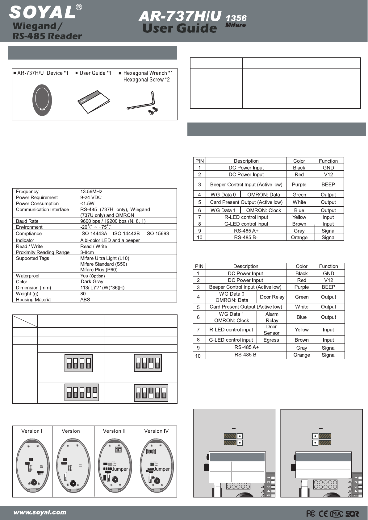
1. AR-737H/U1356 INTODUCTION
1.1 Contents
1.2 MIFARE
Mifare is the most widely applied contactless smart card technology
developed by PHILIPS with ISO standard.
1.3 Function Support
AR-737H/U 1356 adopts PHILIPS high-security proven standard and
meets the high performance.(On the mode of 737 platform) Its MIFARE
chip equip the read & write function to ensure auxiliary WG reader
(AR-737U 1356) or networking reader (AR-737H 1356) .
1.4 Specification
1.6 Wiegand Format Setting
Output format
WG34
WG26
ABA10
Serial ASCII
J1 (DIP_SW1)
Open (OFF)
Close (ON)
Open (OFF)
Close (ON)
2. PIN DEFINE
2.1 Wiring of AR-737H/U (Version I )
J2 (DIP_SW2)
Open (OFF)
Open (OFF)
Close (ON)
Close (ON)
1.5 Difference in Versions
Version
III
IV
I
II
Mode
JP3 Open JP3 Close
JP3 Open JP3 Close
6-PIN Jumper select “WG”
DIP_SW
6-PIN Jumper select “WG”
DIP_SW
6-PIN Jumper select “OUTPUT”
DIP_SW
1ON2 3 4
6-PIN Jumper select “OUTPUT”
DIP_SW
1ON2 3 4 5
AR-737HAR-737U
1ON2 3 4
1ON2 3 4 5
Note: 1.Version IV & afterward could be adjusted to H or U by dip-switch
and 6-pin jumper
2.Version I-III have to be changed by hardware modification.
DIP_SW
DIP_SW
2.1 Wiring of AR-737H/U (Version II & afterward)
2.3 Adding for Version III & afterward
The version III adds a 6-pin jumper for door&alarm relay driver and
WG switching. Its setting should follow the rule below:
WG OUTPUT
WD1
WD0
ALARM
DOOR
AR-737U
PIN
Function Wiegand
Green/Blue
Data 0
Data 1
WD1
WD0
PIN
Function
AR-737H
Orange/Gray
Relay triger
ALARM
DOOR
Page 2

3.1.1 AR-737H1356 connection to PC
1
3.1.2 Software setting from Soyal device tools
2
3
4
5
6
Select communication port.
Enter the target AR-737H’s Node ID (To ignore Node ID , enter 255)
Enable or disable the functions of AR-737H.
Click “write” to download new setting to device.
Click ”Read” to upload parameters from device to
Node737 application.
The screen will show current device parameter and its version,
and then key-in the Node ID you want to change.
6
4
5
2
1
3
Read Write
Exit
3. INSTALLATION DIAGRAM
3.2 AR-737U connect to AR-721H
AR-721H
3.4 AR-737H connect to EM lock & Exit Button with
Relay board
3.3 AR-737U connect to AR-829E, AR-727H
AR-737H
RS-485 A+
RS-485 B-
Exit Button
4. APENDIX
Be sure to record the user number, the user name, the card ID number
(card code)and the user code. It’s import to keep this information
in a secure place. A block user log form has been included for purpose.
Do not write on this form; the form is as a photocopy master.
User No. User Code User Name Site code : Card code
v080813
Page 3

1
2
3
4
5
6
Mode
Unit
737U
125(WG)
Version IV
DIP_SW6.7.8
737H
125(RS-485)
1.6 Indicator Displaying Way While Card Flashin
1. AR-737H/U
125 INTRODUCTION
1.3 Difference in Versions
AR-737HAR-737U
Mode
Version
JP2 Open
JP2 Open
4-PIN Jumper select“WG”
JP2 Close
6-PIN Jumper select “OUTPUT”
JP2 Close
4-PIN Jumper select “OUTPUT”
I
II
III
IV
V
The AR-737H/U125 is a proximity reader which allows performing
as an auxiliary WG reader(AR-737U
125) or networking
reader(AR-737H
125)
1.1 Contents
1.2 Specification
JP2
Jumper
6
6
7
7
Jumper
JP2
Jumper
Jumper
JP2
6-PIN Jumper select “WG”
8-PIN Jumper select “OUTPUT”8-PIN Jumper select “WG”
Version I Version II Version III Version IV
Version V
1.7 Adding for Version II & III & IV
The version ll , lll & IV add a 6-pin jumper for wiegand signal or relay output
selection. Its setting should follow the rules as below:
Frequency
Power Requirement
Power Consumption
Baud Rate
Environment
Indicator
Read / Write
Proximity Reading Range
Supported Tags
Waterproof
Color
Dimension(mm)
Weight(g)
Housing Material
Communication Interface
125KHz
9-24 VDC
<1.5W
RS-485(737H only),Wiegand
(737U only)and OMRON
9600 bps / 19200 bps(N,8,1)
-20 C~+75 C
A bi-color LED and a beeper
Read only
12-20cm
EM4001/EM4012 compliant
Yes(Option)
Dark Gray
113(L)x71(W)x36(H)
80
ABS
o
o
1
2
3
4
JP2 Open
5-PIN Jumper select“WG”
1
2
3
4
5
JP2 Close
5-PIN Jumper select “OUTPUT”
1
2
3
4
5
1
2
3
4
1
2
3
4
5
6
1
2
3
4
5
6
1
2
3
4
5
6
7
8
7
8
WG OUTPUT
WG OUTPUT
AR-737U
Function Wiegand
Green/Blue
PIN
AR-737H
Function
PIN
Relay triger
Green/Blue
SOYAL warrants that the product(s)shall be free from manufacturing
defects in materials and workmanship for a period of fifteen(15)
months from the date of delivery provided that the product was properly
installed and used.
on the PCB board ,
because it is SOYAL warranty.
Please visit WWW.SOYAL.COM to download
the Soyal software, Manual, Catalog & User guide
Data 0
Data 1
0506-123456
AR-737HXXXXXX
Note: Do not tear a paster that
1.4 Mode Setting
1.5 Wiegand Format Setting
JP2
VersionI,II,III
Open(Off)
Close(On)
Version IV
DIP_SW6
Open(Off)
Close(On) J7.Open(Off)
J8.Open(Off)
J6.Close(On)
J6.Open(Off)
J7.Close(On)
J8.Close(On)
Page 4

3. INSTALLATION DIAGRAM
3.1.1 AR-737H125 connection to PC
PIN DEFINE
2.1 Wiring of AR-737H/U 125 (Version I)
2.2 Wiring of AR-737H/U 125 (Version II& III & IV)
PIN DEFINE
v080821
1
2
3
4
5
6
Select communication port.
Enter the target AR-737H’s Node ID (To ignore Node ID , enter 255)
Enable or disable the functions of AR-737H.
Click “write” to download new setting to device.
Click ”Read” to upload parameters from device to
Node737 application.
The screen will show current device parameter and its version,
and then key-in the Node ID you want to change.
3.2 AR-737U connect to AR-721H
AR-721H
3.4 AR-737H connect to EM lock & Exit Button with Relay board
3.3 AR-737U connect to AR-829E, AR-727H
AR-737H
RS-485 A+
RS-485 B-
Exit Button
3.1.2 Software setting from Soyal device tools
6
4
5
2
1
3
Read Write
Exit
 Loading...