

Page 1
Soyal AR727HV3 hardware operation manual
Revision: V1
Date released: 1 Nov 2006
UM_SoyalAR727HV3V1
SOYAL
Access Control System
1
1. Add - Card ID
2. Add - RF-learn
3. Suspend - Addr
4. Suspend – ID #
5. Delete - Addr
6. Delete – ID#
7. Recover - Addr
8. Recover –ID #
9. Antipass Group
1.Node ID
2.Auto Open Zone
3.Door Relay Tm
4.Door Close Tm
5.Alarm Relay Tm
6.Alarm Delay Tm
7.Arming Delay Tm
8.Arming PWD
9.Arming Pulse
1.Password
2.Access Mode
3.Extend Options
4.Single Floor
5.Multi Floors
1.Auto Relock
2.Egress(R.T.E.)
3.Attendance
4.Master Node
5.Force Open…
6.Close & Stop
7.Anti-passback
8.Duress Code
9.Factory Reset
0.Key(#) is Bell
1.Add/Delete
2.User Setting
3.Parameters(1)
4.Parameters(2)
5.Tools
6.Quit
7.Quit & Arming
1.Language
2.Master Code
3.Master Range
4.Terminal Port
5.AR721R32 Port
6.Open TimeZone
7.Informations
8.Clock Setting
9.Control Mode
0.View Events
Function Menu
2
Table of Contents
Page
1. Main Feature --------------------------------- 4
2. Control Mode --------------------------------- 5
3. Notice --------------------------------- 6
How to know card ID of user address? -------------------------------- 6
LCD display show card ID except user address
(ex. 00005) when the user flash card? -------------------------------- 6
How to know how many users in the system now? -------------------------------- 6
How to know which item at your hand? --------------------------------- 7
How to start/suspend (auto open zone)? ---------------------------------- 7
How to disarming? ---------------------------------- 7
How to restore master code to the factory default?--------------------------------- 7
How to reset all parameter to the factory default?----------------------------------- 7
How to set the time on AR-727H? ---------------------------------- 8
How to enable bell output? ----------------------------------- 8
How to check the historical records? ------------------------------------ 8
4. Front Panel & Functions ------------------------------------- 9
5. Mode 4 / 8 / 9 ------------------------------------- 10
5.1 Card Editing ------------------------------------- 10
5.2 Access Mode ------------------------------------- 11
5.3 Duress function ------------------------------------- 12
5.4 Force on/off code ------------------------------------ 12
6 Mode 6 ------------------------------------ 14
6.1 Card editing ----------------------------------- 14
6.2 Access mode ----------------------------------- 14
7 Quick Guide ----------------------------------- 15
8 Function description ----------------------------------- 16
9 Special designed --------------------------------- 19
9.1 Connecting one AR-727H with 2 AR-661U for Anti-pass-back ------------- 19
9.2 How AR-727 connects with a weigand reader
(AR-721K, AR-721U, AR-661U) and to apply
to anti-pass back --------------------------------- 20
9.3 How to set multi AR-727H connects with a net
controller and to apply to anti-pass-back -------------------------------- 20
9.4 How to setting the weigand reader
(AR-721U, AR-721K, AR-661U) and AR-727H
at the same net controller to apply to the
anti-pass-back -------------------------------- 20
9.5 How to set that user arrive single floor or multi-floor -------------------------- 21
3
9.6 How to set AR-401RO16 parameter ------------------------------
22
10 Installation -------------------------------- 23
10.1 Step -------------------------------23
10.2 Installation Notice --------------------------------- 23
11 Wiring --------------------------------- 26
12 Installation diagram -------------------------------- 27
12.1 Magnetic lock --------------------------------
27
12.2 Electric bolt lock -------------------------------- 28
12.3 Electric strike -------------------------------- 29
12.4 Magnetic door contacts and alarm system ---------------------------------- 30
12.5 Wiegand reader --------------------------------
31
12.6 Networking installation -------------------------------- 32
12.6.1 two set of AR-716EV2 parallel installation ----------------------------- 33
12.6.2 AR-716EV2, AR-829E and AR-727H
parallel installation ---------------------------- 34
12.7 Lift controller AR-401RO16 installation ------------------------------- 35
12.1 AR-727H & AR-801CM & PC installation ------------------------------- 36
12.2 RS-232 Printer --------------------------------------------------- 37
13 Software Application ----------------------------------------------------- 38
14 Troubleshooting --------------------------------------------------------- 39
15 Return of Products ------------------------------------ 39
16 Warranty --------------------------------- 39
17 Transponder Record Table ---------------------------------- 40
18 Specification -------------------------------- 41
Page 2
4
1. Main Features
With waterproof, could be installed outside.
Special feature for stand-alone use:
◎ Keep last 1200 transactions
◎ Editable 2 time zone for door release purpose
◎ Controller needless anti-pass back:: AR-727H supports
anti-pass back with its external reader.
Master Cards range assignable.
Unlimited Site Code.
Clear and big LCD panel with 4 line
messages. (128 * 64 graphic)
One RS-485 Port supported for networking(via controller or directly).
Built-in one Door sensor and Arming on/off input.
Support with keypad locks immd & all cards entrance allowance before cards editing
finished.
Support remote operation to relays on networking controller AR-716EV2/AR-716Ei via
Force on/off code.
Support with Auto-relock automatically and keypad locked if continuous wrong code
inputted.
Control mode, card capacity and card type assignable by user directly.
Built-in a proximity reader, a external wiegand reader port and IC card reader
(optional).
Auto-discriminating between stand-alone & networking system, AR-727H could
connect with controller AR-716EV2, AR-716Ei to have multi-door anti-pass back.
Alarm function available. (Tamper, Force entrance, door open too long)
Universal serial port supported for LED display, printer, lift controller, etc
5
2. Control Mode
AR-727HV3
MODE 4
Stand-alone
MODE 6
Stand-alone
MODE 8
Stand-alone
Networking
Card user
Capacity
1024 65536 1024
Depend on
Controller
Access Mode
Card only
Card & PIN
User nbr. & PIN
Card only
Card only
Card & PIN
PIN only
Depend on
Anti-pass Back Single door
×
Single door
Multi-door
anti-pass back
(16 doors)
Control Mode in
Networking
Mode 4
×
Mode 8
Mode 4
Or
Mode 8
Note WG32 WG 16 WG32 WG32
Lift control
32 stop
1024 card users
×
32 stop
1024 card user
32 stop
1024 card
users
How to set Mode 4 ,Mode 6 , Mode 8 and Mode 9:
Step1: * + 1 2 3 4 5 6 + #
enter the “FUNCTION MENU”
Step2: Tool / control mode (command:59)
1:M4 2:M6 3:M8 4:M9, input Mode value.
tags format—1:EM 2:SOYAL, input card value.
Note:
1. M4=M9 In AR-727HV3 version.
2. Changing control mode “from Mode 6 to Mode 4” or “from Mode 4 to Mode 6”, it is
necessary to delete all card user data first.
Depend on controller: For example, controller AR-716EV2 has 15,000 card users
capacity.
Lift control: For 1024 card users, everyone could be assigned for single floor or
multi-floor access.
6
3. Notice
Keep AR-727H away from the followings:
Keep away from magnets or any magnetized items.
Do not apply strong shock to 727H
After flash master card and press F1 F2 F3 F4 or #
within 2 seconds can enter the “FUNCTION MENU”.
Master Cards range assignable.
Default value: user address 00000 – 00004.
Each card has 10 digits code, including Site code (5 digits) and Card code (5 digits).
Neither the Site Code nor the Card Code numbers can be 0.
After card editing finished, Site Code and Card Code is not important anymore.
System will require a USER ADDRESS instead.
User can request to exit through the controlled door without using transponder (and
without causing an alarm condition), by pressing an exit button. This will operate the
door relay for the programmed door relay release time & stop alarm.
How to know card ID of user address? (For example: which card ID do we want to
know user address 00003)
Step1: * + 1 2 3 4 5 6 + #
enter the “FUNCTION MENU”
Step2: Add/Delete (command 1)
Step3: Add / Card ID (command 1)
Step4: Enter user address 00003, then you will see card ID.
LCD display show card ID except user address (ex. 00005) when the user flash card?
How to do?
Step1: * + 1 2 3 4 5 6 + #
enter the “FUNCTION MENU”
Step2: Parameters (1) (command 3)
Step3: Node ID (command 1)
Step4: Set Node ID
Step5: Then, the system will ask if show card ID?
1. No 2. WG 3. ABA 4. HEX Cur.: 1
Step6: If select 2. WG, for example as follows:
User address 00005 for card ID 00020:25000
When user flash card, LCD display will show
both user address 00005 and card ID 00020:25000.
Note that CPU version must be at least 4.1 or up.
How to know how many users in the system now? (Not including suspend card)
Step1:
*
+ 1 2 3 4 5 6 + #
enter the “FUNCTION MENU”
Step2: Tools (command 5)
Step3: Informations (command 7)
AR-727H Ver 3.4 Users: 00010 (There are already 10 users in the system)
How to know which item at your hand?
7
(For 125K system or Mifare system)
Step1: * + 1 2 3 4 5 6 + #
enter the “FUNCTION MENU”
Step2: Tools (command 5)
Step3: Informations (command 7)
"AR-727H1356 V4.2""Users: 00000 ""Messages: "
Or
"AR-727H Ver 4.2 ""Users: 00000 ""Messages: "
How to start/suspend (auto open zone)?
Step1: main manual
Step2: tools (command 5)
Step3: setting Open Time Zone (command 6)
Step4: come back to main manual
Step5: Parameters (1) (command 3)
Step6: start Auto open zone function (command 2)
Step7: Yes / No
Note: The electronic lock would be locked until first one flash card on the reader
when the system enter auto open time zone.
And electronic lock will be locked that sensor feels door closed when system exit
auto open time zone.
How to disarming?
(1) User can be disarming by normal access mode once
violating anti-pass-back resulting in alarm.
(2) User can be disarming by valid card when alarm happen.
(3) * + 1 2 3 4 5 6 + #
enter the “FUNCTION MENU”
Step1: main manual
Step2: Parameters (2) (command 4)
Step3: Close Door Stop Alarm (command 6), then enter 1: YES.
How to restore master code to the factory default (123456)?
If the master code is forgotten it can be restored to the factory default (123456).
Remove the AR-727H from the mounting plate, disconnect power, remove AR-727H
CPU, install AR-727H-CLE CPU, and restore power about 10 seconds. Then
disconnect power, remove AR-727H-LCE CPU, install AR-727H CPU, and restore
power.
How to reset all parameter to the factory default?
Step1: * + 1 2 3 4 5 6 + #
enter the “FUNCTION MENU”
Step2: Parameters(2) (command 4)
Step3: Factory Reset (command 9)
Then, LCD display will show “Initial System……” message to reset all parameter to
factory default.
Note that CPU version must be at least 3.8 or up.
How to set the time on AR-727H?
Page 3
8
Step1: * + 1 2 3 4 5 6 + #
enter the “FUNCTION MENU”
Step2: Tools (command 5)
Step3: Clock Setting (command 8)
Step4: Input Date&Time YyMmDdHhMmSs
How to enable bell output?
Step1: * + 1 2 3 4 5 6 + #
enter the “FUNCTION MENU”
Step2: Parameter(2) (command 4)
Step3: Key(#) is Bell (command 0)
Step4: Press(#) On Bell 1:YES 2:No Data:0
Step5: Enter 1:YES
How to check the historical records?
(1) Press * + 1 2 3 4 5 6 + #
enter the “FUNCTION MENU”.
(2) “Tools (Command 5)” -> “View Events (Command 0)”
(3) Then, you will see the following message from LED screen:
A
01/16 15:45
:25
FRI 00001 001
Work Status :
A: Duty On
B: Duty Off
C: Overtime on
D: Overtime off
E: Break out
F: Break RTN
G: Go
H: Return
Date Time
Serial Number
Week User Address
9
Error (Red)
Input ndicator Arming Green)
Alarm (Red)
Transmission:
Receive (Green)
OK(Green)
Reading (Green)
Send (Red)
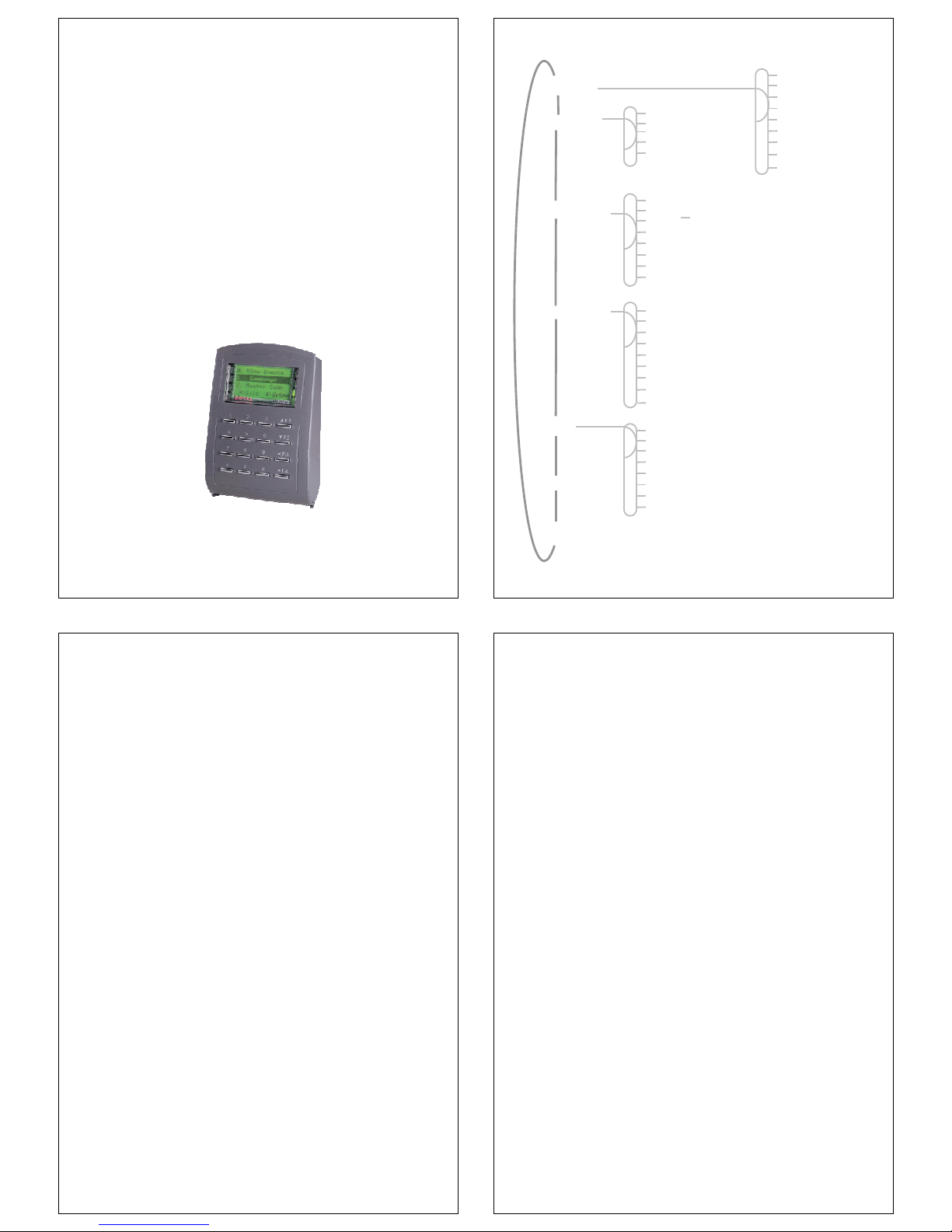
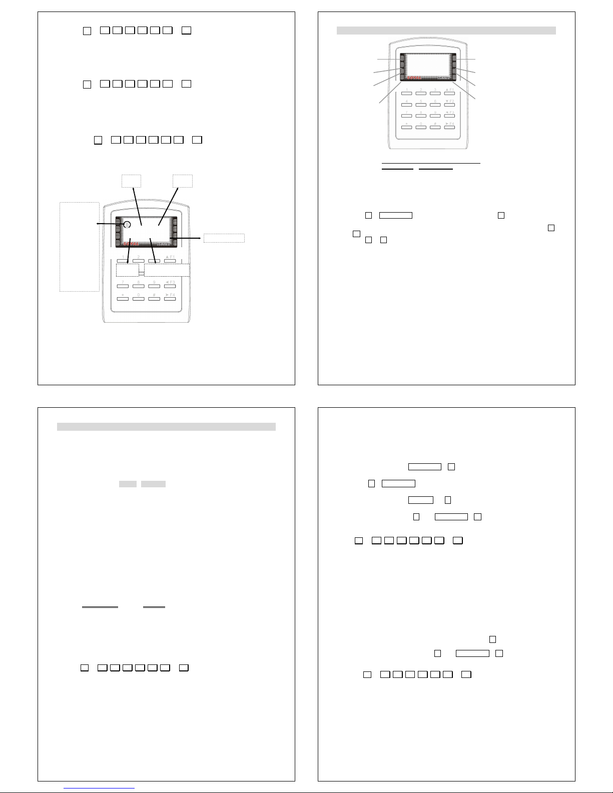
4. Front Panel & Functions
Keypad
Attendance
Press 1 time Press 2 times
F1 Up Duty on Break out
F2 Down Duty off Break RTN
F3 Correct Overtime on Go
F4 Overtime off Return
* Esc
# Enter
Other:
◎ Press * + Master Code (default : 123456, changeable) + #,
to enter “Function Menu”
◎ Before card editing finished, the master could enter “Function Menu” and press 0
+ F4 for all cards entrance allowance.
◎ Press * + # to lock / unlock keypad immd.
Functions:
1. System will automatically exit from FUNCTION MENU, if no key or card entry is
made within 30 seconds.
2. In FUNCTION MENU, LED [OK] will flash continuously and quickly.
3. In card access mode, flashing qualified card on the unit
LED [OK] and LED [Reading] will light up, a beep sound and LCD panel message
shown [OK],
4. Flashing unqualified card on the unit
LED [ERROR] and LED [Reading] light up, two beeps sound and LCD panel
message shown [Invalid Card!].
5. Green LED [ARMING] light up in “Arming On”.
6. Red LED [ALARM] lights up if any abnormal condition arisen.
7. Continuous wrong “PIN Code” or “Master Code” will make keypad locked for 30
seconds, LED [Error] light up and LCD panel shown [keypad Locked].
8. Once Alarm arisen, user must push exit button or flashing qualified card to release
and return to standby state.
9. Transmission:
Receive [Green] lights up when it receives message from PC or its external reader.
Send [Red] lights up when AR-727H sends data to PC
10
5. Mode 4 / 8
Pre-explanation
Arming PWD (4 digits)
Default value:1234
Could be setup via Function Menu (Function no. 38)
PIN Code (4 digits)
Could be setup via Function Menu (Function no. 21)
Or, via 701 Client \ Setting \ User card
Duress Code (4 sets, 4 digits)
Networking System:
Default value:1111 ; 2222 ; 3333 ; 4444
Changeable via 701 Server\ Setting \ 701 Configuration \
Duress Code
Stand-alone System:
Default value:4321
Changeable via Function Menu (Function no. 48)
Force on/off Code (4 sets, 4 digits)
Networking System:
Default value:1111 ; 1111 ; 1111 ; 1111
Changeable via 701 Server\ Setting \ 701 Configuration \
Duress Code
5.1 Card Editing
After entering Function Mode, user uses following order to edit cards.
Function Nbr.
Add→Card ID 11
Add→RF learn 12
Delete→Addr 15
Delete→ID# 16
Recover→Addr 17
Recover→ID# 18
How to edit ten pcs sequential cards?
( Default access mode is Card only)
Step1: * + 1 2 3 4 5 6 + #
enter the “FUNCTION MENU”
Step2: Add/Delete (command 1)
Step3: Add→RF learn (command 2)
Step4: Then, LCD display will show as follow:
Please follow LCD display indicator to edit card
Step5: InputStartAddr (0-00999)
Enter 1, start from user no. 1
Step6: Tag Uints (pcs) Must be Sequence (1-00999)
Enter 10
Step7: Close Tag Into RF Area
Present the lowest card code of card to the unit.
11
5.2 Access Mode
Users can select one of the following access modes
5.2.1 Card Only
Access the door by flashing card
Open door & turn Arming on / off:
Flash card, then press Arming PWD + F1
Not open door & turn arming on / off:
Press * + Arming PWD, then flash card
5.2.2 Card and PIN
Flash card, then press PIN Code + #
Open door & turn Arming on / off:
Flash card, press PIN code & #, then Arming PWD + F1
Not open door & turn arming on / off: Not available
How to set access mode of user is card and PIN?
Step1: * + 1 2 3 4 5 6 + #
enter the “FUNCTION MENU”
Step2: User Setting (command 2)
Step3: Access Mode (command 2)
Step4: Enter user number, Then, LCD display will show as follow:
1:Card 2:or PIN 3:& PIN 4:Pause Data: 1
Please select number 3: & PIN
Step5: Return to main menu to set the password of user
Step6: User Setting (command 2)
Step7: Password (command 1)
Step8: Enter user number
Then, LCD display will show as follow:
Input 4 Digit No. Range:0001~9999 Data:
5.2.3 User address and PIN (Mode 4)
Press keypad: User address (5 digit), then PIN code & #
Open door & turn Arming on / off:
User address, press PIN code & #, then Arming PWD + F1
Not open door & turn arming on / off: Not available
How to set access mode of user is card or PIN?
Step1: * + 1 2 3 4 5 6 + #
enter the “FUNCTION MENU”
Step2: User Setting (command 2)
Step3: Access Mode (command 2)
Step4: Enter user number, Then, LCD display will show as follow:
1:Card 2:or PIN 3:& PIN 4:Pause Data: 1
Please select number 2:or PIN
Step5: Return to main menu to set the password of user
Step6: User Setting (command 2)
Step7: Password (command 1)
Step8: Enter user number
Then, LCD display will show as follow:
Input 4 Digit No. Range:0001~9999 Data:
Page 4
12
5.2.4 PIN only (Mode 8)
Same as Card Only
Or, press keypad
◎ Door access: PIN code (4 digit)
◎ Open door & turn Arming on / off:
PIN code & #, then Arming PWD + F1
◎Not open door & turn arming on / off: Not available
How to set access mode of user is PIN only?
Step1: * + 1 2 3 4 5 6 + #
enter the “FUNCTION MENU”
Step2: User Setting (command 2)
Step3: Access Mode (command 2)
Step4: Enter user number, Then, LCD display will show as follow:
1:Card 2:or PIN 3:& PIN 4:Pause Data: 1
Please select number 2:or PIN
Step5: Return to main menu to set the password of user
Step6: User Setting (command 2)
Step7: Password (command 1)
Step8: Enter user number, Then, LCD display will show as follow:
Input 4 Digit No. Range:0001~9999 Data:
5.2.5 Change PIN code
AR-727H connects with PC, running 701 client and set PIN code variable.
By user: Flash card, then press PIN code (4 digit) twice + # )
By 701 client \ setting \ user card
Not connecting with PC
Entering Function menu \ User setting \ Password
5.3 Duress function
This function could help users to send a message to the computer asking for help.
Only available in networking state, running 701 Server and setting 4 sets of
Duress code on
PC. (Anyone of these 4 sets is workable.)
This function is not available for CARD ONLY access mode and mode 8 directly
4-digit PIN.
Access Mode Command Format
Card Only Not available
Card and PIN Flash card, then press Duress code & #
Users addr. and PIN
(Mode 4)
Press user address,
then Duress code & #
PIN Only (Mode 8) Duress code
5.4 Force on/off Code (4 sets, 4 digits)
Only workable in networking system, running 701 Server and setting 4 sets of
Force code on PC. (Anyone of these 4 sets is workable.)
User could press related code to turn on / off its connected equipment, diagram as
below.
13
After access OK, press following order to turn on / off its connected equipment.
Access mode ON/Off
Order
ON
Flashing card+Force code+ Code+0+ #
Card only
Off
Flashing card+Force code+ Code+1+ #
ON
Flashing card+User code +Force code+Code+ 0
+#
Card + user
code
Off
Flashing card+User code +Force code+Code+ 1+
#
ON
User no. + User code +Force code+ Code+ 0+ #
User no.
+ user
code (Mode 4)
Off
User no. + User code +Force code+ Code+ 1+ #
ON
User code +Force code+ Code+0 +#
User code only
(Mode 8)
Off
User code +Force code+ Code+1 +#
This function is good for force control television, air conditioning, audio, etc. by
Relay-1, 2, 3, 4 on the multi-door networking controller.
To avoid the conflict of the use of each controller relay, it is user responsibility to
define each controller relay for one purpose use only.
PC board of Controller AR-716EV2 / AR-727E
COM
JP4
V12
CN5
DI.4
DI.2
DI.1
DI.3
COM
D10
D9
D11
K4
RELAY
K3
D12
RELAY
JP3
K1
K3
K4
K2
K2
RELAYRELAY
K1
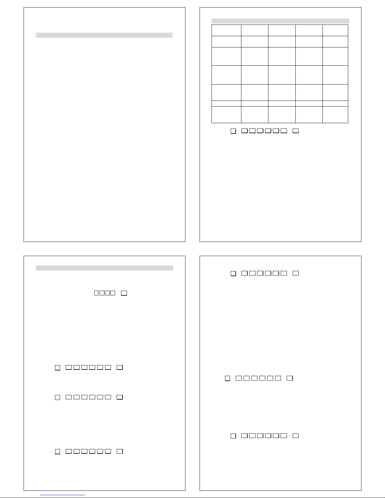
Relay Code
K1 16
K2 17
K3 18
K4 19
14
6. Mode 6
6.1 Card Editing
Under Mode 6, the system built in card code from 00001 to 63200 itself, so user
can only suspend or recover cards, not allowed to add or delete.
The card which its card code is over than 63200 can’t be used under Mode 6.
After entering Function Mode, user uses following order to edit cards.
Function Nbr.
Suspend→Addr 13
Delete→Addr 15
Recover→Addr 17
How to start / stop using cards?
Example: Start using cards, which card ID from 12345: 00001 to 12345: 00100,
totally 100 cards in sequence.
Step1: Entering Function Mode
Step2: Recover -> Addr. (Order no. 17)
Step3: Input Start Addr. -> 00001
Step4: Input End Addr.-> 00100
Succeed!
6.2 Access Mode
Under Mode 6, with different Arming PWD and Duress Code, users have different
access mode as below.
Arming PWD =
0
Arming PWD ≠
0
Duress Code =0 Duress Code
≠0
Mode 6
Access Mode
Card only Card and Arming
PWD
Duress Code
not workable
Duress Code
only
15
7. Quick Guide (Function Menu)
Under Function Menu, you could just press the indicative nbr. to get into concerning
set-up screen directly.
Function Nbr. Function Nbr.
Add→Card ID
11 Alarm Relay Tm 36
Add→RF – learn
12 Arming Delay Tm 37
Suspend→Addr
13 Arming PWD 38
Suspend→ID #
14 Arming Pulse 39
Delete→Addr
15
Delete→ID #
16 Auto Relock 41
Recover→Addr
17 Egress (R.T.E.) 42
Recover→ID #
18 Attendance 43
Antipass Group 19 Master Node 44
Force Open.. 45
Password 21 Close & Stop 46
Access Mode 22 Anti-pass back 47
Extend Options 23 Duress Code 48
Single Floor 24
Multi Floors 25
Language (English) 511
Master Code 52
Master Range 53
Terminal Port 54
AR721R32 Node 55
Node ID 31 Open Time Zone 56
Auto Open Zone 32 Information 57
Door Relay Tm 33 Clock Setting 58
Door Close Tm 34 Control Mode 59
Alarm Relay Tm 35 View Events 50
Page 5

16
8. Function description
24 Single Floor To setup user for single floor access
(This function is only workable under the situation that
AR-727H combined with AR-401RO16 and Control Mode is not
Mode 6.)
25 Multi Floors To setup user for multi floors access
(This function is only workable under the situation that
AR-727H combined with AR-401RO16 and Control Mode is not
Mode 6.)
For example: User 0001 access to floor 17, 22, 31, 32
(Supposed no basement)
1. Entering “Function Menu”
2. Press 25
3. Enter user address: 00001
4. Select range: 2 (for 17 – 32)
1: 01 –16 2: 17 – 32
5. 0 -> stop 1 -> Yes
1000010000000011
31 Node ID To setup Node ID (default: 001), range from 001 to 254
33 Door Relay Tm To setup how long the time will be that door close after a card
flashing.
Range: 0 ~ 600 (sec.)
To set value “0” will make door keep opening, after 2nd card
flashing, then door close. (Default value: 7 sec.)
34 Door Close Tm Extended time for door opening time.
(Default value: 15 sec.)
35 Alarm Relay Tm When abnormal condition arisen, how long the alarm will take
place.
Range: 0 ~ 600 (sec.)
To set value “0” will make alarm relay keep on until disarming,
then alarm relay off. (Default value: 7 sec.)
36 Alarm Delay Tm The time between setting Alarm on and its real starting working
time.
(Default value: 1 sec.)
37 Arming Delay Tm The time between setting Arming on and its real starting
working time.
Range: 0 ~ 600 (sec.)
(Default value: 1 sec.)
39 Arming Pulse Range: 0 ~ 2500 (sec.)
TTT = 000: Latch (Toggle)
(Default value: 1 sec.)
56 Open Time Zone Set door open / close automatically.
Details:
1. Enter “Function Menu”
2. Setup opening time first, Function no. 56
3. Auto Open Zone, Function no. 32
1: Yes 2: No
17
Drawing explanation:
1. Time schedule for Door Relay, Wait Delay (Door Close Tm),
Alarm Delay, Alarm Relay
2. Arming Delay, Arming on
Arming Delay Timing
Timing 1 Sequence-
Flashing card OK
Door
Close Tm
Alarm
Delay
Alarm
Relay
Door
Relay
Arming
Delay
Arming
Relay
Flashing card OK
If abnormal conditions arisen, will cause
Alarm
E.g. Door open too long (over allowed time)
Force open
Arming Delay Time
Timing 1
Check Point AArming is set
Signal Output
Arming
Signal Output
Arming
If TTT = 000
Level Triggle
Arming
Signal Output
If TTT = 200
Pulse Trigger
Pulse Trigger
If TTT = 050
0.5 Second
2.0 Seconds
Sequence
18
After arming is set, the system enters TTiimmiinngg 11 SSeeqquueennccee. Right on CChheecckk PPooiinntt AA, the
system is in arming situation and enters Arming Mode, if door is close, the system
engages the Timing 2 Sequences, if door is open, it will wait until the door is closed to
engage the Timing 2 Sequences.
Timing 2 Sequences-
Door opened by not using “Forced Open”:
In arming situation, the system enters TTiimmiinngg 22 SSeeqquueenncceess once the door is opened by
not using “Forced Open”. During TTiimmee PPeerriioodd BB, the system is back to arming situation
if door closed, if door is still open right on CChheecckk PPooiinntt CC, alarm is activated after TTiimmee
PPeerriioodd D
D. User can disarm the system in TTiimmee PPeerriioodd DD to avoid the alarm generated,
or disarm the system in TTiimmee PPeerriioodd EE to turn off the alarm which is activating.
Door opened by using “Forced Open” and if “Forced Open” feature, Command 28,
is disabled:
In arming situation, the system enters AAllaarrmm DDeellaayy TTiimmee right away once using “Forced
Open” opens the door and if “Forced Open” feature is disabled. The alarm is activated
after TTiimmee PPeerriioodd DD. User can disarm the system in TTiimmee PPeerriioodd DD to avoid the alarm
generated, or disarm the system in TTiimmee PPeerriioodd EE to turn off the alarm which is
activating.
Door opened by using “Forced Open” and if “Forced Open” feature, Command 28,
is enabled:
In arming situation, the alarm is generated and system enters AAllaarrmm TTiimmee right away
once using “Forced Open” opens the door and if “Forced Open” feature is enabled. User
can disarm the system in TTiimmee PPeerriioodd EE to turn off the alarm that is activating.
Signal Output
Arming or Disarming Signal Output- RED WHITE, CN2
Once arming is set, after Arming Delay Time period, the system generates a Level
Trigger if TTT=000, and a Pulse Trigger if TTT>000 and the time period of the Pulse
Trigger is based on the calculation 0.01xTTT second(s).
For TTT=000, entering the Edit Mode or disarming the system will reset the Level
Trigger.
For TTT>000, entering the Edit Mode every time or disarming the system will generate
a Pulse Trigger.
Timing 2
Sequences
Alarm Time
Alarm Delay Time
Check Point C
Arming Idle Time
Door Unlock Time
Door is opened
Time Period B Time Period D Time Period E
Arming Delay Time
Timing 1
Sequences
In Arming ModeArming is set
Signal Output
Arming
Signal Output
Arming
If TTT = 000
Level Triggle
Arming
Signal Output
If TTT = 200
Pulse Trigger
Pulse Trigger
If TTT = 050
0.5 Second
2.0 Seconds
DisarmingorEdit Mode
Enter
Edit Mode
Enter
19
Arming Switch Setting Signal Output- ORANGE WHITE, CN2
Once Arming switch is pressed, a Level Trigger is generated until Arming switch is
released to reset this signal.
Card Present Signal Output- Brown, CN2
Any identifiable tag in the RF field, it will output a low level signal; a Level Trigger is
generated until a tag is absent to reset this signal.
9. Special Design
9.1 AR-727H connected with 2 pcs of AR-661U long-range reader (Set one
AR-661U being Exit reader and the other one being Entry reader) to apply to
Anti-pass back.
CPU version must be at least 3.2 or up.
In stand-alone system, without connecting to any controller, AR-727H could
integrate with 2 pcs of AR-661U to apply to anti-pass back.
◎ No special setting up necessary for AR-727H.
◎ Set one AR-661U with wiegand 34 bit format output and the other one with
38 bit. (Please refer to manual of AR-661U to have details.)
◎ Set card to have anti-pass back checking.
(Order no. 19)
This special design is especially suitable for car parking control.
The special design is only workable with AR-661U, not available with AR-721U,
AR-721K. (wiegand reader)
Soyal Product AR-829E (CPU version at least 5.6) 、AR-721H4 (CPU version at
least 3.1V) also have this special design.
The original function that AR-727H connecting with one wiegand reader
(AR-661U, AR-721U, AR-721K) to apply to Anti-pass back is still available.
Arming Switch
Output
Press button for
Set Arming
Release utton
for disarming
Card Present
Signal Output
Identifiable
tag Present
Identifiable
tag
Absent
Page 6

20
9.2 How AR-727 connects with a weigand reader (AR-721K, AR-721U, AR-661U)
and to apply to anti-pass back?
(1) Main manu
(2) Input command:47,
enable antipass—1:YES 2:NO,input1;
in or out –1:in 2: out,input default value(1 or 2 ).
attention:if AR-727H would be in door and then the weigan reader would be out
door.
9.3 How to set multi AR-727H connects with a net controller and to apply to
anti-pass back?
Both card and reader have to apply to anti-pass back.
1.card setting:
step1:701 Client
step2:user card edit
step3:mark anti-pass back.
. 2. reader setting (AR-727H):
step1:main manu
step2:command 47
step3: enable antipass—1:YES 2:NO,input1;
in or out –1:in 2: out,input default value(1 or 2 ).
9.4 How to setting the weigand reader (AR-721U, AR-721K, AR-661U) and
AR-727H at the same net controller to apply to the anti-pass back?
Both card and reader have to apply to anti-pass back
Card setting: step1:701 Client
step2:user card edit
step3:mark anti-pass back.
Hardware setting: weigand reader (AR-721U, AR-721K):
Set controller WG port as in or out if WG port is port 1 then would be in door and
port 2 would be out door.
AR-716Ei PCB
Port 1
(Channel 17)
Port 2
(Channel 18)
21
Software setting: 701 Server.
Step1: 701E Parameter
Step2: door number
Step3:mark [Door Number 17]or [Door Number 18]
AR-727H setting:
(1) main manu
(2) command 47
enable anti-pass back 1:YES 2:NO,input1;
in or out –1:in 2: out,input default value(1 or 2)
Attention: if weigand reader would be in door then AR-727H would be our door.
9.5 How to set that user arrive single floor or multi-floor?
Either way to set user arrive single floor or multi-floor function.
1. Set by keypad for standalone installation
(AR-727H+AR-829L485+AR-401RO16)
Set user arrive single floor
Step1: * + 1 2 3 4 5 6 + #
enter the “FUNCTION MENU”
Step2: User Setting (command 2)
Step3: Single Floor (command 4)
Step4: Enter user address and set to access which one floor.
Set user arrive multi-floor
Step1: * + 1 2 3 4 5 6 + #
enter the “FUNCTION MENU”
Step2: User Setting (command 2)
Step3: Single Floor (command 5)
Step4: Please refer to “function description” to get detailed
explanation.
2. Set by software for networking installation
(PC+AR-801CM+AR-716EV2+AR-727H+AR-829L485+
AR-401RO16)
22
Go to 701 Client \ User card edit \ User Access Floor Edit
Select User.
Select controller and reader node that manages that elevator.
Select the card user can access which floor.
Click “Write to Controller”.
9.6 How to set AR-401RO16 parameter?
(ex. Card Release Tm)
Step1: * + 1 2 3 4 5 6 + #
enter the “FUNCTION MENU”
Step2: Tools (command 5)
Step3: AR-721R32 Node (command 5)
Step4: Input NodeID, Card Release Tm and P.B Release
Tm (Default value: 7 sec.)
Note:
1. AR-401RO16 has no push button input function, but you still enter push button
input second in order to complete this command. Otherwise, this command will be
failed.
2. They are one-way transmission is between AR-727H and AR-401RO16, so you
will find that you change Card Release Tm from 7 sec. to 10 sec. But the parameter
will be stay default value 7 sec. Don’t worry about this matter. Actually, it is already
changeable.
23
10. Installation
10.1 Steps:
1. Use the screwdriver to screw the mounting plate on the wall.
2. Pull cable ends through the access hole in the mounting plate.
Connect plug 7 pins to socket CN1
Connect plug 4 pins to socket CN2
Connect plug 8 pins to socket CN3
Connect plug 3 pins to socket CN5
3. Attach AR-727H to the mounting plate and install screw (supplied) into the hole at the
bottom with the Allen wrench (supplied).
4. Apply power. Green LED [POWER] will light up, a beep sound and LCD panel
message will show up.
10.2 Installation Notice:
1. The distance between AR-727H and its auxiliary reader should be more than 50 cm
and less than 12 meter. (Suggested value)
AR-727H could be fixed inside the secure area as an exit and its auxiliary reader
outside as an entrance reader, but not directly behind AR-727H.
2. The reading range of AR-727H will be up to15 cm. However, when AR-727H or its
auxiliary reader is mounted directly on a metal surface, the reading distance
decreases slightly. To reduce this effect, we suggest inserting a wood or plastic
between the mounting surface and the unit.
3. Exit Switch input must be a dry contact, without voltage present.
4. AR-727H does not supply power to operate electric strike or magnetic locks, a
separated power supply are required.
Refer to strike or magnetic lock manufactures instructions, if common power supply
is used for both AR-727H and electronic door lock; make sure to install the diode,
which is provided with AR-727H.
5. Power supply should be at least 9 VDC to max. 24 VDC and at least 3W. DC power
should be clean and filtered with no more than 0.3 VAC ripple (Peak to Peak). Do not
run AC power in the same cable with DC power to AR-727H. While it is always
preferable to use a separate power supply for AR-727H and strike.
Page 7

24
6. Run the following cables to the AR-727H location. Conduit is recommended to reduce
the effects of EMI/RFI and for physical protection of the wires.
Cable Types and Distances
Wire Application Cable Type Description
From Power Supply 2-cond, 18-22 AWG n/a
From Locking Device and power
supply or gate operator
2-cond. See Mfr’s
Specifications
n/a
From external alarm system’s Door
Monitor Switch (for shunting)
2-cond, 18-22 AWG 100 m
From Exit Button 2-cond, 18-22 AWG 100 m
From Optional Auxiliary Reader 2-cond unshielded 22 AWG,
plus a separate 4-cond,
shielded 22-24 AWG cable
50 cm - 12 m
7. Hardware connecting distance suggestion as follows:
a. RS-232: The distance between PC and converter (AR-801CM) can not be more
than 2 meters
b. RS-485: The distance between converter (AR-801CM) and
the farthest controller (or reader) can not be more than 300 meters.
c. Wiegand: The distance between RS-485 reader (or controller)
and Wiegand reader can not be more than within 3 to 5 meters.
d. Do not run AC power in the same pipe with communication wire (See drawing 2).
It should be separate installation (See drawing 1).
(Drawing 1)
(Drawing 2)
Separate installation
Reader Lock
Lock
In the same pipe
Reader
25
8. We suggest that the customer use ”Shield Twisted Pair” and avoid
Star wiring for good communication when installation.
a. We suggest using the following cable in RS-485 communication.
b. Please use the following installation method, it is correct.
c. Don’t use the following installation method, it will cause communication error.
801CM
OR
Controller
Controller
OR
Reader
801CM
OR
Controller
Controller
OR
Reader
vv
xx
26
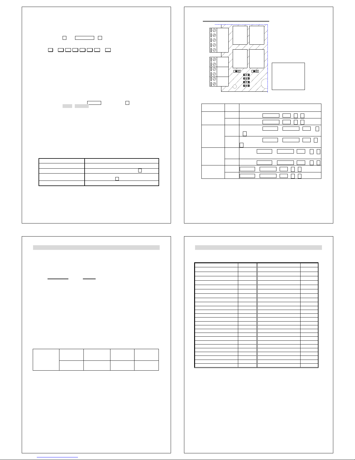
11. Wiring
Table 1 - Connector CN3 Color Coding
Wire Application Wire Color Description
1 Blue White (N.O.)DC24V1Amp
Door Relay
2 Purple White (N.C.)DC24V1Amp
Door/Alarm Relay
3 White (COM)DC24V1Amp
Door Sensor 4 Orange Negative Trigger Input
Exit Switch 5 Purple Negative Trigger Input
Alarm Relay
6 Gray N.O. / N.C. Optional
7 Thick Red DC Power 12V
Power
8 Thick Black DC Power 0V
Table 2 - Connector CN1 Color Coding
Wire Application Wire Color Description
1 Thick Green RS-485(B-)
Networking
2 Thick Blue RS-485(A+)
3 Thin Blue Wiegand DAT:1 Input
ABA Clock Input
Wiegand
4 Thin Green Wiegand DAT:0 Input
ABA Data Input
Buzzer 5 Pink Buzzer Output 5V/100mA, Low
6 Brown LED Green Output 5V/20mA, Max
LED
7 Yellow LED Red Output 5V/20mA, Max
Table 3 - Connector CN5 Color Coding
Wire Application Wire Color Description
1 Red N.C.
2 Orange COM
Tamper Switch
3 Yellow N.O.
Table 4 - Connector CN2 Color Coding
Function Wire Color Description
Arming
Setting Switch
1
Orange
White
Latch type
Serial Port 2
Yellow
White
Serial output (Transistor open collector)
(4800,N,8,1)
Arming LED 3 Red White Arming output (Active low)
Card Present 4
Brown
White
Card present output active low
(Transit output)
OFF ON
Purple White
Blue White
COM
Gray
White
NO
NC
JP1
Alarm Relay
Door Relay
K1
K2
27
12. Installation diagram
12.1 Magnetic lock
N
O
.
C
O
M
.
-
G
ND
+
1
2
V
D
C
The installation of 727H and magnetic lock
White( COM. )
Lock( -GND )
Purple White( N.C. )
-GND
Power Supply
12VDC 2A
Purple
Black( - GND )
Red( +12VDC )
DOOR EXIT
Push Button
CN3
Power Supply
12VDC 2A
Lock(+ 12VDC )
+ 12VDC
Magnetic Lock
CN3
AR-727H
CN5
CN1
CN2
Page 8

28
12.2 Electric bolt lock
Red( + 12VDC )
Black( - GND )
Purple
Push Button
+ 12VDC
-
G
N
D
Power Supply
12VDC 2A
White( COM. )
DOOR EXIT
Lock(+ 12VDC )
Lock( -GND )
Electric Bolt Lock
CN1
Blue White( NO. )
CN3
CN5
AR-727H
CN2
CN3
The installation of 727H and electric bolt lock
C
O
M
.
N
O
.
+
1
2
V
D
C
-
G
N
D
Power Supply
12VDC 2A
29
12.3 Electric strike
+
1
2
V
D
C
-
G
N
D
N
O
.
C
O
M
.
The installation of 727H and electric strike
Power Supply
12VDC 2A
DOOR EXIT
Push Button
Purple
Black( - GND )
Red( + 12VDC )
Blue White( NO. )
White( COM. )
CN3
Lock(+ 12VDC )
+ 12VDC
12VDC 2A
Power Supply
Electric Strike
Lock( -GND )
-GND
AR-727H
CN5
CN3CN1
CN2
30
12.4 Magnetic door contacts and alarm system
- GND
+ 12VDC
ALM.
N.C.
COM.
N.O.
+ 12VDC
-
G
N
D
+
1
2
V
D
C
The installation of 727H, magnetic door contacts
and alarm system
Alarm System
Power Supply
12VDC 2A
Black( - GND )
Red( +12VDC )
Gray( ALM. )
Red( + 12VDC )
Black( - GND )
Magnetic Door Contacts( COM. )
CN3
Orange( Door Sensor )
Magnetic Door Contacts
(
NC. )
12VDC 2A
Power Supply
Magnetic door
contacts
CN1
CN5
AR-727H
CN2
CN3
31
12.5 Wiegand reader
G
r
e
e
n
B
l
u
e
Y
e
l
l
o
w
P
u
r
p
l
e
B
r
o
w
n
The installation of 727H and auxiliary readers
721U
12VDC 2A
Power Supply
Red(+12VDC)
Black
Red
1
721K
Red
Black
CN1
1
~
Yellow
Brown
CN2
Green
Pink
Blue
661U
Black(-GND)
Brown
Yellow
Green
Pink
Blue
727H
CN3
CN1
Page 9

32
AR-737U
Black
Power Supply
12VDC 2A
The installation of 727H and auxiliary readers 737U
Red
P
u
r
p
l
e
B
l
u
e
G
r
e
e
n
B
r
o
w
n
Y
e
l
l
o
w
AR-727H
Yellow
Black(-GND)
Red(+ 12VDC)
1
CN3
Green
Brown
Pink
Blue
CN1
33
12.6 Networking installation
12.6.1 two set of AR-716EV2 parallel installation
To
Node: 009
Node: 016
To
Node: 008
Node: 001
Note:1.The connecting disance between the 801cm and your pc can not be more than 2m.
AR-727H
AR-727H AR-727H
Green
Blue
Blue
Green
Green
Blue
Green
Blue
CN1
CN1 CN1
connect to PC
15VDC 2A
Power Supply
Controller
Next
Red
Black
Blue
Black
Green
Red
AR-727H and AR-716E/727E neworking installation
AR-716E
or
AR-727E
CN1CN3
CN3CN1
CN5
CN2
~
~
CN1
~
~
CN1CN3
CN5
CN2
CH1
JP2JP1
HOST
CN3
CH2
CN2
BV+
Vin
Vin
GND
BV-
727i
CN2
AR-727H
CN5
CN3CN1
CN2
CN5
~ ~
~ ~
JP1 JP2
Vin
Vin
BV+
BV-
CN2
CN1
CN3
CH1
HOST
CH2
727i
AR-716E
or
AR-727E
GND
CN1
34
12.6.2 AR-716EV2, AR-829E and AR-727H parallel installation
727i
CN3
Red
JP1 J P2
Black
CH2
HOST
CN2
CN1
CN2
AR-727H, AR-829E and 716EV2 networking installation
CN2
Green
Blue
AR-829E
AR-727H
½u
¬ õ
½u
¶ Â
GND
Vin
CN1
Vin
BV-
BV+
綠
線
½u
ÂÅ
~
~
CH1
Power supply
15VDC 2A
CN2
CN1
CN5
CN3
AR-727H
Blue
Green
¦ Ü
Node: 009
Node: 016
CN1
CN3CN1
CN5
CN1
Green
Blue
CN3
CN5
CN1
CN1
Green
Blue
CN2
AR-727H
CN2
Next Controller
~
~
AR-716EV2
or
AR-727Ei
Minimum 2 meter
connect to PC
35
12.7 Lift controller AR-401RO16 installation
Power Supply
12VDC 2.4A
Diagram of AR-727H and AR-401RO16
Black
Yellow
-
+
CN
CN1
CN
CN3
Red
Red
+
-
+
Black
DC 12V
Green
Blue
-
-
+
+
-
+
-
Page 10

36
12.8 AR-727H & AR-801CM & PC installation
Power Supply
Red
Black
Blue
To PC
connect to PC
Minimum 2 meter
Green
AR-727H
15VDC 2A
Power Supply
Green
Blue
CN5
CN1 CN3
CN1
CN2
AR-801CM
CN3
-
G
N
D
+ 12VDC
Lock (+12VDC )
Lock ( -GND )
Electric Bolt Lock
Power Supply
12VDC 2A
Blue White ( NO. )
White ( COM. )
Purple
Black ( - GND )
Red ( +12VDC )
N
O
.
C
O
M
.
Push Button
DOOR EXIT
12VDC 2A
The installation of 727H, 801CM and PC
37
12.9 RS-232 Printer
12.9.1 Printer setting - Baud rate: 4800, N, 8, 1
12.9.2 Hardware installation
12.9.3 Hardware serial port format – select “printer format”
Step1:
*
+ 1 2 3 4 5 6 +
#
enter the “FUNCTION MENU”
Step2: Tools (command 5)
Step3: Terminal Port (command 4)
Step4: 1: AR401RO16 2: LED
3: PRN 4: Duress
Current Data: 1
Please enter 3, let serial port become printer format.
12.9.4 Print result
Date Week Time Card ID Status
05/03/2004 MON 20:24:16 0000000248 Power On Ver 3.5
05/03/2004 MON 20:24:18 02: Reader Off Line
05/03/2004 MON 20:24:22 0000000250 Clear Message!!
05/03/2004 MON 20:25:01 01: Set Clock!
05/03/2004 MON 20:25:30 01:00001 Card Access OK
05/03/2004 MON 20:26:20 01: Egress!
05/03/2004 MON 20:35:23 01:00001 Card Access OK
The above data is printer when someone flash card, Egress, power on/off, clear
message and set clock. But note that the data will be not printed from invalid card.
The Wiring of 727H and printer (SH24)
TP1 DATA
4K7
V12
GND
Serial Port
(2nd Pin of CN2)
Yellow White
AR-727H
4K7
B
GND
E
B
C
E
C
C1815
TX
DB25 male
Replace Circuit (Distance between
AR-727H & SH24 Printer <1M)
Suggest Circuit
MAX232A
TX
Black (8th Pin of CN3)
Pin GND
7
Pin RX (in)
2
SH24
Printer
38
13. Software Application
13.1 Configuration
PC + AR-801CM + AR-727HV3
13.2 The difference between AR-727H and AR-727HV3
AR-727HV3 CPU: Version 5.1 UP / Hardware: 24LC256
13.3 Software Version
Support 701 Server Ver 6.22 & 701 Client Ver 6.28
13.4 Software function via PC
1. Eleven sets of Time Zone (set via Time Zone Edit)
a. From Time zone 1 to Time zone 11
b. Support to linkable for each zone.
c. Support the holiday if enable
2. Up to 120 holidays that can be set in a year starting from the
editing date. (set via Holiday Edit)
3. Different time zone for each user (set via User Card Edit)
4. Which code will show in daily transaction record?
Code Status Code Status
M11 Normal Access M03 Invalid
M16 Door open via Egress Button M17 Alarming
M04 Time Zone error M30 Anti-pass-back error
M01 PIN code error
5. Time and Attendance function
6. Work status of LCD display of the reader when standalone
View Message when standalone, it will show work status on left top corner if it is
normal access (See Also: historical records page 10).
Other will show code.
7. Auto-show work status (set via Time Zone Edit)
a. Time zone 00 (Default), range from Sunday to Saturday.
b. Work status
00:00 – 00:00 stand for fixed Duty on in work status
23:59 – 23:59 stand for fixed Duty off in work status
00:01 – 00:01 stand for retain last status that user press in work status
XX:XX – YY:YY stand for as follows:
For example, 09:00-18:00
Work status will show Duty on before 9 o’clock, show Duty off between 9 o’clock
and 18 o’clock and show Overtime Off after 18 o’clock.
39
14. Troubleshooting
Questions Answer
No appearance 1. Check power, if it is 9 – 24 VDC adaptor?
2. Check if the polarity is correct?
Can not connect to PC 1. Check if Transmission LED light up? (Green / Red)
2. Check 701 Server, if set-up is correct?
Please refer to 701 Server manual for details.
3. If connecting to PC via AR-801CM converter, check if the
power (Green) light up?
How to find out Card
ID with a user
address?
1. Entering “Function Menu”
2. Press 11
3. Entering “user address”
How many Cards exist
in system?
1. Entering “Function Menu”
2. Press 57
15. Return of Products
Please contact the distributor who sold the unit. All service and repairs must be done
through an authorized distributor.
16. Warranty
SOYAL warrants that the product(s) shall be free from manufacturing defects in
materials and workmanship for a period of twelve (12) months from the date of delivery
provided that the product was properly installed and used. The foregoing warranty shall
not apply to defects resulting from abuse, misuse, accident, unauthorized alteration or
repair, neglect, acts of God (such as floods, fire, etc.). SOYAL shall, at its option, either
repair or replace product(s) which prove to be defective within the warranty period.
SOYAL will replace any product found to be defective within the first three months of
purchase provided said product was properly installed and used. Distributor agrees to
insure the product or assume the risk of loss or damage in transit to prepay shipping
charges and to use the original shipping container or equivalent. Customers shall seek
assistance from the distributor who sold you product(s). Repaired or replaced product(s)
are warranted for ninety (90) days from the date of repair or replacement, or for the
remainder of the original product’s warranty period, whichever is longer.
Note:
Don’t tear a paster such as S/N: 727H Warranty B-0307-000107 on the PCB
board, it is SOYAL warranty.
Page 11

40
17. Transponder Record Table
Be sure to record the user number, the user name, the card ID number (site code: card
code), and the user code and keep this information in a secure place. A black user log
form has been included for purpose. Do not write on this form; use it as a photocopy
master
.
User Add. User Name Site code: Card code PIN code
Programmed by: Date:
Company Name:
Company Address:
City:
Other Information:
41
18. Specification
Mode No. Mode 4 Mode 6 Mode 8
RF Frequency 125KHz / 13.56MHz
Event Log 1,200 - 1,200
Power Requirement 10-24VDC
Power Consumption < 3W
Communication Interface RS-485
Baud Rate 9600 bps (N, 8, 1)
Environment -20 to +75
DI Input Egress Button / Door Sensor / Arming Switch
Compliance ISO14443A (13.56M only)
Door Relay Time 0-600 sec.
Alarm Relay Time 0-600 sec.
Tamper Resist. Switch
Limit Switch (Form C)
Aux. WG Port WG 26/34, ABA-II, OMRON
Editing Interface Controller /
PC Software
Controller Controller / PC
Software
Proximity Reading Range
10-18cm (125K) / 3-8cm (13.56M)
Serial Out TTL (4800bps, N, 8, 1)
Color Dark Pearl Gray / Navy
Dimensions (mm) 126(H)*91(W)*46(D)
Weight (g)
200±10
Housing Material ABS
LCD Panel (pixel) 128*64 (4 line messages, 16 characters each line)
 Loading...