

Page 1
SOYAL
ACCESS CONTROL SYSTEM
®
AR-727iV3 / AR-727CM V3
V110107
VCC
VCC
VCC
B
A
U3
SN75176BP
U0RX
U0TX
VCC
R10
1K
Q1
2N2222A
R15
10K
R16
10K
RV1
SA85CA
FUSE1
F1
F2
BA+
FUSE2
RV2
SA85CA
R11
10K
Pin 21
Pin 18
Pin 19
U0RTS
GND
GND
8
7
6
5
2
1
3
4
RE
R
DE
D
GND
GND
GND
GND
GND
DS232
U1
1
2
3
4
5
6
7
8
16
15
14
13
12
11
10
9
1
CN2
DB9
6
2
7
3
8
4
9
5
PC_CTS
PC_RTS
U0CTS
U0RTS
U0TX
U0RX
Pin 20
Pin 21
Pin 19
Pin 18
PC_RX
PC_RTS
PC_CTS
DB9-6
PC_TX
DB9-4
A+
B-
C1+
V+
C1C2+
C2VT2OUT
R2IN
VCC
GND
T1OUT
R1IN
R1OUT
T1IN
T2IN
R2OUT
GND
VCC
PC_TX
PC_RX
C3
104P
C4
104P
C1
104P
C2
104P
C5
104P
CN1
8
7
6
5
4
3
2
1
RJ45
R18
727i J1
BASE
2.0mm
C12
103P/1206/1KV
Shading
G_GND
1
2
3
4
5
6
7
8
9
10
11
12
R17
RX-
TX-
RX+
TX+
75
75
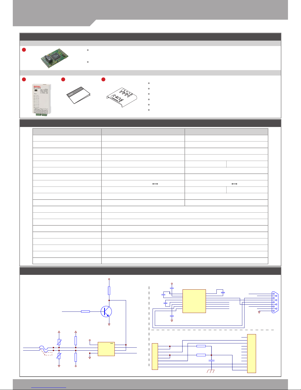
Contents
1
Product
1
Product
2
User Guide
3
Accessories
Specication
727i V3 Diagram
AR-727iV3
AR-727CM V3
AR-727iV3 Supports varies Ethernet protocol (TCP server/TCP), which is a Serial-to-Ethernet device to connect to
networking.
Small volume with compact design, 45mm*28mm size less than a semi credit card, easily connect to Serial device
to get on networking with 10/100M.
32 bits/50MHz ARM CPU upgrades serial device to networking device.
Compatible with 5V and 3V system.
Dual UART port supported and 4K/4K Rx/Tx buffer.
Easy to use with compact volume. Need for external components.
10/100 Mbps auto-negotiation Ethernet interface.
The Virtual COM software builds 1-255 virtual series communication ports
onto your computer.
Part NO.
Type
Input Voltage
Power Consumption
Dimensions
Port 1
Port 2
RS-485 Transmission Direction Control
Interface
Active Distance
Surge protection
N.W.(g)
Thunder Protection
Data Bits
Stop Bits
Parity Check
Baudrate
Network Protocols
Software Conguration Interface
Operating Temperature
Operating Humidity
AR-727i V3
36-pin 2mm compact package
5 VDC (±5%)
<0.5W
45(L)x28(W)x14(H)
TTL 3.3VDC (Rx, Tx, RTS, CTS)
TTL 3.3VDC (Rx, Tx, RTS, CTS)
RTS pin
10/100M Base T Ethernet UART(TTL)
-
-
15
AR-727CM V3
Ethernet to Serial Port Device
9-24 VDC (±5%)
<2W
106.5(L)x66(W)x27.7(H)
RS-485 (A+, B-)
-
10/100M Base T Ethernet RS-232/RS-485
16KV
86±5
1.5KV
8, 9
1, 2
None, Even, Odd
4800-115200 bps
ARP, IP, TCP Client, UDP, ICMP, HTTP, DHCP, NetBIOS, SNMP
V1, V2, V3
,
Web Console
-20℃~+60
℃
5 to 95% RH
RS-232 (Rx, Tx, RTS, CTS) RS-485 (A+, B-)
a.AR-727i V3 Connects to RS-485 b.AR-727i V3 Connects to RS-232
c.AR-727i V3 Connects to RJ-45
2M/RS-232 300M/RS-485
Page 2
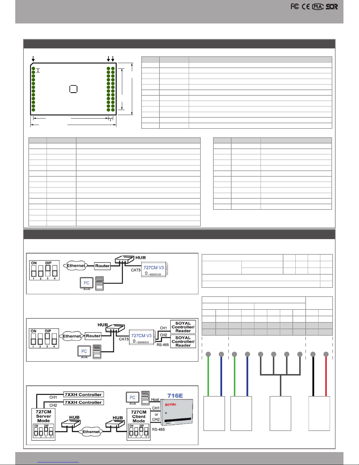
V110107
J1
Pin No.
1
2
3
4
5
6
7
8
9
10
11
12
Signal
5V
NET RX(-)
NET RX(+)
5V
BUSY LED
LINK LED
ACT LED
RX/TX LED
GND
NET TX(-)
NET TX(+)
BASE
Description
Power input.
Ethernet Network Receive Data(-).
Ethernet Network Receive Data(+).
Power input
Low active for external LED Driver to indicate busy status.
Low active for external LED Driver to indicate cable connected status.
Low active for external LED Driver to indicate TCP/UDP connect status.
Low active for external LED Driver to indicate Ethernet RX/TX status.
Power input.
Ethernet Network Tranceive Data(-).
Ethernet Network Tranceive Data(+).
Connect to shading through 103P/2KV capacitor.
J2
Pin No.
24
23
22
21
20
19
18
17
16
15
14
13
Signal
GND
Reserved
Reserved
U0 RTS
U0 CTS
U0 TX
U0 RX
Factory Reset
DHCP
50Hz
Reset
GND
Description
Power input.
UART channel 0 Request to Send.
UART channel 0 Clear to Send.
UART channel 0 Tranceive Data.
UART channel 0 Receive Data.
Connect to ground more then 3 seconds will reset the module
to Factory Default Value.
AR-727i support Auto Conguration of the IP and gateway
addresses and subnet mask function, but must make sure the
DHCP Server is active.
50Hz square ware output for external watchdog strobe use.
Low active. System reset input.
Power input.
J3
Pin No.
36
35
34
33
32
31
30
29
28
27
26
25
Signal
V33
Reserved
U1 RTS
U1 CTS
U1 RX
U1 TX
Reserved
Reserved
Reserved
Reserved
Reserved
Reserved
Description
3.3V voltage output.(max 20mA)
UART channel 1 Request to Send.
UART channel 1 Clear to Send.
UART channel 1 Receive Data.
UART channel 1Tranceive Data.
J1
1
78.74mil(2mm)
1598.43mil(40.6mm)
78.74mil(2mm)
866.14mil
(22mm)
12 13 25
24 36
J2 J3
28.52mm
1123mil
1835.363mil(46.6mm)
Serial to Ethernet Device
10/ 100 Base-T
AR-727i V3 PIN Assignments
AR-727CM V3 (2 UART Ports): Connection and Conguration
A. IP setting D. DIP Switch Settings
B. Normal use
C. Remoe use (Server mode and client mode)
Normal Run Mode
and Networking Setup
RS-232
Two RS-485 Wires
2
ON
OFF
LB-
1
20
COM
RTS
5
16
DO2
LB-
3
18
N.O.
Rx
7
14
DI3
GND
9
12
DI1
LA+
2
19
N.C.
CH2
RS-485
CH1
POWER
Tx
6
15
DO3
LA+
4
17
DO1
CTS
8
13
DI2
V12
10
11
DI0
1DIP Switch 3
OFF
ON
DHCP Enable (Auto IP Address Conguration)
DHCP Disable (Auto IP Address Conguration)
4
ON
OFF
RS-485
RS-232
Power
RS-485 RS-232RS-485
※
CH1 only can select either RS-485 or RS-232.
Page 3

SOYAL
ACCESS CONTROL SYSTEM
®
AR-727iV3 / AR-727CM V3
V110107
Web Console
Set up IP Address:
4. Click on [Network Setting] on Main Menu to set up new
IP address.
a. Type the new
IP address
b. Click it to update
5. Click on [User Password] on Main Menu to change.
Type the new User Name &
Password.
3. Login
Type "User name" & "Password" on
the pop up login window.
※
Factory Default :
User name: admin
Password:(NO need to type)
1. Connect the device to a computer, Then turn on your Web Browser
and type "http://192.168.1.127" on IP address to start factory default
webbrowser.
Factory Default
※
http://192.168.1.127 is the factory default, if the IP address has been
changed, the new IP address may be entered.
2. When you type the IP address, you will see the [Current State] page.
The version of ISP Firmware
Current IP address
Main Menu
Page 4

V110107
Serial to Ethernet Device
10/ 100 Base-T
Update the ISP Firmware
Step 1: Execute the software [ UdpUpdater.exe] provided by SOYAL.
Step 3: Click on the lastest rmware, and click on [Open].
Step 2: Click on [Load File] to open the Firmware
Step 4: Then follow the steps:
1. Type the IP address and COM Port
2. Click on [Update Device]
3. Until the screen appears [Program Completed]
4. It mean the upgrade is successed, and click on
[Exit] to leave.
1
3
2 4
6. Click on [Port 0 Setting] or [Port 1 Setting] on Main Menu to set the port.
Set the [Operation Mode] at the [Server] or the [Client]
.
At the [Server]: [Remote Port] need to be set [0].
At the [Client]: [Remote Port] need to be set as the server port.
At the [Server]: [Remote IP] need to be set [0.0.0.0].
At the [Client]: [Remote IP] need to be set as the server IP address.
[UART to NET minimum bytes]: Proposes to set more than 900.
 Loading...