

Page 1
SOYAL
ACCESS CONTROL SYSTEM
Contents
1
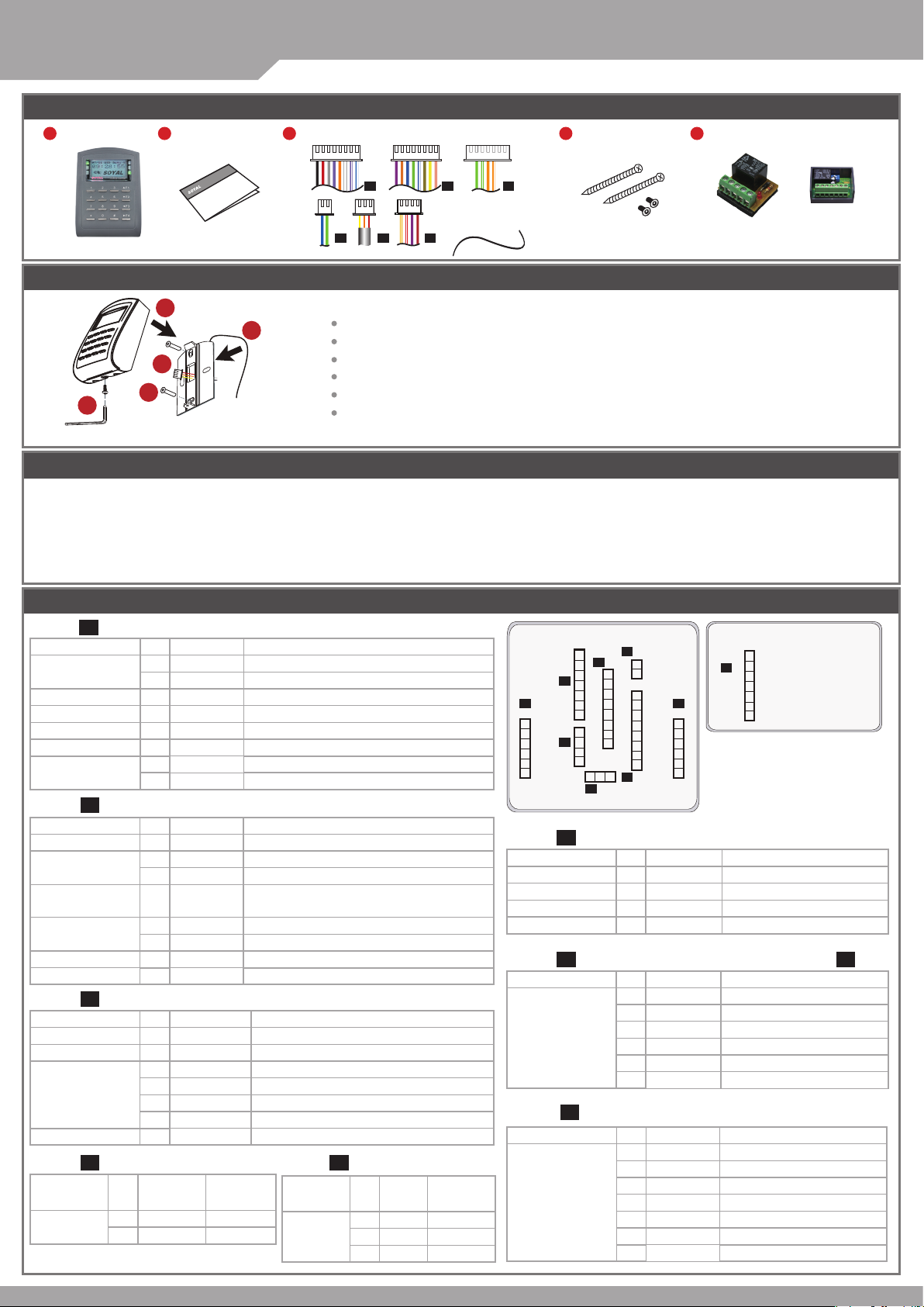
Products
2
User Guide
®
3
Terminal Cables
AR-727 (H-V5)
P1 P2 P3
V140701
4
Tools
5
Optional
P4 P5 P6
Installation
4
1
2
5
3
Notice
1.Tubing:
2.Wire selection:
3.Power supply:
Connector Table
Cable: P1
Wire Application Wire Color Description
Lock Relay 1 Blue White (N.O.)DC24V1Amp
Lock Relay COM 3 White (COM)DC24V1Amp
Door Contact 4 Orange Negative Trigger Input
Exit Switch 5 Purple Negative Trigger Input
Alarm Relay 6 Gray DC24V1Amp
Power 7 Thick Red DC 12V
Cable:
Wire Application Wire Color Description
Beeper 1 Pink Beeper Output
LED
Door Output 4 Blue White
Wiegand
WG Door
WG Exit Switch 8 Purple Negative Trigger Input
Cable:
Wire Application Wire Color Description
TCP/IP Output 3
Cable: P4
Wire
Application
RS-485 for Lift
Controller
The communication wires and power line should NOT be bound in the same conduit or tubing.
Use AWG 22-24 Shielded Twist Pair to avoid star wiring ,CAT 5 cable for TCP/IP connection
Don’t equip reader and lock with the same power supply. The power for reader may be unstable when the lock is activating, that may make the
reader malfunction.
The standard installation: Door relay and lock use the same power supply, and reader use independent power supply.
More details please go download by www.soyal.com
◎
2
Purple White
(N.C.)DC24V1Amp
8 Thick Black DC 0V
P2
5V/100mA, Low
2 Yellow Red LED Output
5V/20mA, Max
3 Brown Green LED Output
Transistor Output Max. 12V/100mA
(Open Collector Active Low)
5 Thin Green Wiegand DAT: 0 Input
6 Thin Blue Wiegand DAT: 1 Input
Contact
7 Orange Negative Trigger Input
P3
1 --- --2 --- ---
Orange White
4 Orange
5 Green White
6 Green
7 --- ---
Wire Color Description
1 Thick Green RS-485(B-)
2 Thick Blue RS-485(A+)
Net - TX+
Net - TXNet - RX+
Net - RX-
Cable:
Wire
Application
Anti-Tamper
Switch
P5
Water proof Strip
AR-821RB
AR-721RB
Digital Relay
Attach the water proof strip to the mounting plate.
Pull the cables from the square hole of the mounting plate.
Use a screwdriver to screw the base onto the wall.
Connect the terminal cables to the body and attach the body to the mounting plate.
Assemble the covers with the Allen key and screws (accessories supplied).
Turn on the power, the LED will light and hear the beep sound, you will see "Ready"" on LCD board.
Main PCB LCD-PCB
CN6
P4
7
CN5
P2
CN3
2
1
8
7
6
8
5
7
4
3
2
1
CN11
6
5
4
3
2
1
CN4
P1
6
5
P3
4
CN7
Optional Optional
P9
CN9
6
5
4
3
2
1
Cable:
P6
CN8
P6
3
2
1
4
3
2
1
321
P5
P7
6
5
4
3
2
1
Optional
P8
CN18
7
6
5
4
3
2
1
Wire Application Wire Color Description
5V/20mA, Max
Power 1 Red DC 12V
Security trigger signal
2 Purple Security trigger signal Output
Output
Arming 3 Red White Arming Output
Duress 4 Yellow White Duress Output
Cable: CN11
P7
(Optional:Lift Control w/ AR-725L485)
/ CN9
P9
Wire Application Wire Color Description
TTL Port 1 Black DC 0V
2 Yellow
3 White
4 Orange
TX
TE
RX
5 Red DC 5V
6 --- ---
Cable: CN18
P8
(Optional:HID ProxII RF Module)
Wire Application Wire Color Description
ANT 1
ANT 2
Wire Color Description
1 Red N.C.
2 Orange COM
3 Yellow N.O.
HID RF Module 1 Orange
2
Purple
3 Black DC 0V
4 Red DC 5V
5 Blue Wiegand DAT: 1 Input
6 Green Wiegand DAT: 0 Input
7 White --
Page 2
P
W
R
E
R
R
02/24
14 : 49 : 04
FRI
Duty : 0
P
W
R
E
R
R
02
24
14 : 49 : 04
FRI
Duty : 0
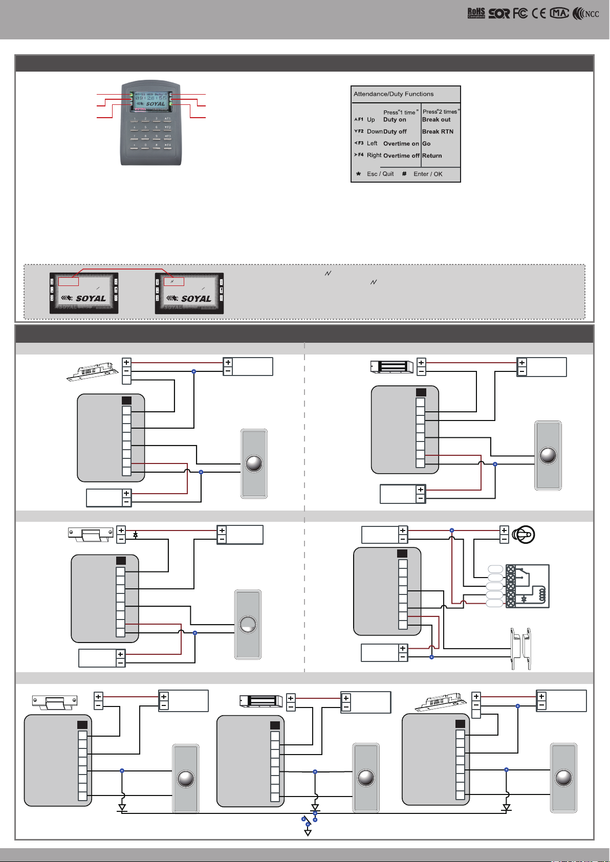
Front Panel & Indicator
LCD Access Controller
V140701
Power
Alarm
Alarm
(Green)
(Red)
(Green)
(Green)
OK
Error
(Red)
In processing
(Green)
1. System will automatically exit from Programming Mode when inactivating for 30 seconds.
2. LED status indicates controller’s mode and status.
OK (green) – blinking constantly when operates in Programming Mode
– or ashing an existed card in card learn mode, it comes 2 beeps warning and LCD panel displays “Same Card: user address / card number”
Error (red) – invalid card with 2 beeps warning and LCD panel displays “Card Number Err!”
– or in anti-pass-back mode, when violates the access, it comes one beep warning and LCD panel displays “Anti-pass Error!”
Arming (green) – arming on status
Alarm (red) – any abnormal condition occurs
3. Keypad will be locked up 30 sec. when constantly entering incorrect pin code or master code.
4. Maximum error in[ut of pin code and master code can be changed via the software 701Server (default: 5 times)
Networking : / and interactively ash between the Month and DAY.
[e.g.] 02/24←→02 24
Stand-alone : No ashing [e.g.] 02/24
(←Reference to picture)
Wiring Diagram
Connect to Electric Bolt
N.O.
COM
PB
12V
GND
E
P1
1
2
3
4
5
6
7
8
Controller
Electric Bolt
POWER
12VD C
12V
GND
Exit Switch
12V
GND
12V
GND
POWER
12VD C
N.O.
GND
EXIT
RTE
Connect to Magnet Lock
Magnet Lock
P1
1
N.C.
2
COM
3
4
5
PB
6
7
12V
8
Controller
GND
POWER
12VD C
12V
GND
GND
12V
GND
Connect to Electric Strike Connect to Door Contact
ALM
12V
GND
P1
12V
GND
1
2
3
4
5
6
7
8
12V
GND
12V
GND
N.C.
N.O.
COM
CTL
12V
Relay Outpot Module
N.C.
Controller
Electric Strike
N.O.
COM
PB
12V
GND
POWER
12VD C
P1
12V
GND
1
2
3
4
5
6
7
8
12V
GND
12V
GND
N.O.
GND
POWER
12VD C
EXIT
RTE
POWER
12VD C
Door Contact
Controller
POWER
12VD C
If any re emergency, the people can escape by press a switch to open all doors
Magnet Lock
P1
1
2
N.C.
COM
3
4
PB
5
6
12V
7
GND
8
12V
GND
POWER
12VDC
EXIT EXIT
Fire Emergency
Electric Bolt
N.O.
COM
PB
12V
GND
12V
GND
E
P1
1
2
3
4
5
6
7
8
Electric Strike
N.O.
COM
PB
12V
GND
P1
12V
GND
1
2
3
4
5
6
7
8
Transistor
POWER
12VDC
RTE
EXIT
IN4007
12V
N.O.
GND
Alarm
Transistor
IN4007
POWER
12VD C
EXIT
RTE
Door Contact
POWER
12VDC
RTERTE
Page 3

SOYAL
ACCESS CONTROL SYSTEM
®
AR-727 (H-V5)
V140701
Strengthen security with AR-721RB
12V
GND
Electric Bolt
1
2
4
1 2 3
P6
DDR
12V
Controller
POWER
12VDC
Adding and Deleting Tag
User capacity: 16384 (00000~16383)
※
12V
GND
3
4
P1
5
6
7
8
12V
GND
12V
GND
POWER
N.C.
N.O.
COM
CTL
12V
GND
PB
AR-721RB
N.O.
12VDC
EXIT
RTE
Connect to Reader
12V
GND
Exit Switch
Electric Bolt
Reader
E
N.C.
N.O.
COM
CTL
12V
BZ
RLED
GLED
WG 0
WG 1
12V
GND
Adding Tag by Tag ID
Access programming mode
→
1
Add/Delete
Add -> Card ID
→
1
Input 5-digit user address
→
Adding Tag by RF Learn Function
Access programming mode
Input Tag Units(pcs)
→
If adding a batch of Sequential tags, please input Tag Units(pcs) in the quantity of the tags and present the
※
1 2
Add/Delete
→
Close Tag into RF Area
→
Add -> RF-Learn
→
Input 5-digit user address
→
tag with the lowest card code to the access controller.
Deleting User Address
Access programming mode
1 5
Add/Delete
→
Delete -> Addr
→
Input Starting address
→
→
Deleting Tag by Tag ID
Access programming mode
1 6
Add/Delete
→
Delete -> ID #
→
Input Site Code
→
Input Card Code
→
Setting up the access mode
Access programming mode
2 2
User Setting
→
→
Access Mode
Input User Address → 0: Invalid; 1: Card ; 2: Card or PIN; 3: Card & PIN
→
P2
BZ
1
RLED
2
GLED
3
Door Output
4
WG 0
5
WG 1
6
7
WG-DS
8
WG-PB
Controller
Input Site Code
→
→
Tag Information
SITE COD E
Input Ending address
POWER
12VDC
P1
1
2
3
4
5
6
12V
7
GND
8
Input Card Code
CARD COD E
Door Contact
N.C.
EXIT
RTE
POWER
12VDC
CARD COD E
SITE COD E
Programming
A. Keyboard Lock/ Unlock
Lock/ Unlock
Press and , and at the same time to lock keyboard.
Press again to unlock.
B. Entering and Exiting Programming Mode
Entering
Input 123456 or PPPPPP
[e.g.] The Default Value= 123456. If already changed the Master Code=
876112, input
87 6112
Access programming mode
→
P.S.If entering no instruction within 30 sec., it will automatically leave the
programming mode.
Exiting
Press the repeatedly
6 7
Quit or Quit and Arming (Please refer
→
to alarm / arming setting)
Changing the Master Code
Access programming mode
6-digit new master code
→
Succeeded
→
5 2
Too l s
→
Master Code
Input the
→
C. Initial setup
Language Setting
Access programming mode
Succeeded → Initial system...
Node ID of Reader Setting
Access programming mode
Input New Node ID : 1~254 (default value:001) → Main Door
→
Number : 0~255 → WG1 Door Number : 0~255 → Show UID
(0=No,1=WG,2=ABA,3=HEX) → Enable DHCP(0:No,1:En,2=Exit)
Succeeded
→
5 1 0
Too l s
→
3 1
Par am eters[1]
→
→
Language
→
EN
→
Node ID
→
D. PIN Code
Access programming mode
5-digit user address
→
Or via 701Client set it on Users screen
2
→
User Setting
→
1
Password
Input 4-digit PIN (0001~9999)
Succeeded
→
→
Input
E. Setting up the alarm / arming
Conditions: 1. Arming enabled 2.Alarm system connected
Application:
1. Door open too long: Door is open longer than door relay time plus
door close time.
2. Force open (Opened without a valid user card): Access by force or
illegal procedure.
3. Door position abnormal: When power is off and then on, reader
on arming before power off.
F. Enable Voice Module (supporting version : F/w Ver 3.02
or later)
Hardware setting
Access programming mode
5
Too l s
2
Voice
→
5
Ext. Comm Port
→
Software Setting
701 Server or
Step 1. Click " Read."
Step 2. Select "Card Reader"
in RS485-2 section.
Step 3. Click "Write" to nish
the setting.
→
Page 4

LCD Access Controller
E. Setting up the alarm / arming
Enable/Disable the arming status:
Standby Mode
Card only Card or PIN Card and PIN
Open the door
Present the tag to reader
4 digits arming PWD
Access Programming mode
Enable: Access programming mode
Restoring Factory Settings
→
→
Input
No open the door
Input 4 digits arming PWD
→
Present the tag to reader
→
7
Quit & Arming
→
Input user address
digits individual PWD
Input 4 digits arming PWD
Disable: Access programming mode
Reset all device parameters and user card data
Reset all device parameters and user card data:
Access programming mode
1 : User Setting ; 2 : System & User
Reset IP Setting:
When the device's power is on, press the【RESET】button the main board untill the ERR (Red) LED of
screen lights up. (Reference to picture)
After operation as above, you will hear the long reminder sound,and wait until the
※
sound disappear then reset the power of the controller,the device will restore factory setting.
Manu Tree
1. Add/ Delete
1. Add > Card ID
2. Add > RF Learn
3. Suspend > Address
4. Suspend > ID #
5. Delete > Address
6. Delete > ID #
7. Recover > Address
8. Recover > ID #
9. Antipass Group
2. User Setting
1. Password
2. Access Mode
3. Extend Options
4. Single Floor
5. Multi Floor
→
Parameters2
Factory Reset →0 : System Param ;
→
94
3. Parameters[1]
1. Node ID
2. OnOff OpenZone
3. Door Relay Tm
4. Door Close Tm
5. Alarm Relay Tm
6. Alarm Delay Tm
7. Arming Delay Tm
8. Arming PWD
4. Parameters[2]
1. Auto Relock
2. Egress(R.T.E)
3. Miscellaneous
4. Force Open
5. Close & Stop
6. Anti-pass-back
7. Duress Code
8. Password Mode
9. Factory Reset
Input 4
→
→ →
→
5. Tools
1. Language
2. Master Code
3. Master Range
4. Terminal Port
5. Ext.Comm Port
6. Open Time Zone
7. Informations
8. Clock Setting
9. Daily Alarm
Present the tag to reader
4 digits individual PWD
Input 4 digits arming PWD
→
V140701
Input
→
→ →
→
6
Quit
6. Quit
7. Quit & Arming
IP Setting
Open your Web Browser and input factory default IP
ad d r ess: http :// 192 .168.1 .12 7
If the IP address of AR-727 (H-V5)
has changed We must enter the
new IP address.
Log-in User Password
When you choose the "Networking Setting" or "User Password" at rst.
Log-in window will pop out and please input
At the Factory Default
※
User name: admin
Password: No as default value,so please just press “OK” to log-in
Networking Setting
You will nd initial IP Address 192.168.1.127 and check
MAC Address is the same as sticker on Ethernet Module
device. Please revise IP address you want, and then click
“Update” button. After updating the IP, please re-connect
the Web Browser by new IP address.
admin
寫入一 組 新 的IP位置之後
Update
再按下
既可寫入新的IP位置
User Password
Change the log-in password to lock the IP setting of
Ethernet Module.
The password composes of 10 characters at most, it can be
either A~Z or 0~9.
變更新的登入者密碼最多可設定
10
A~Z和0~9
個字元
來組合
 Loading...