

Page 1
SOYAL
ACCESS CONTROL SYSTEM
Contents
AR-725E-M
1
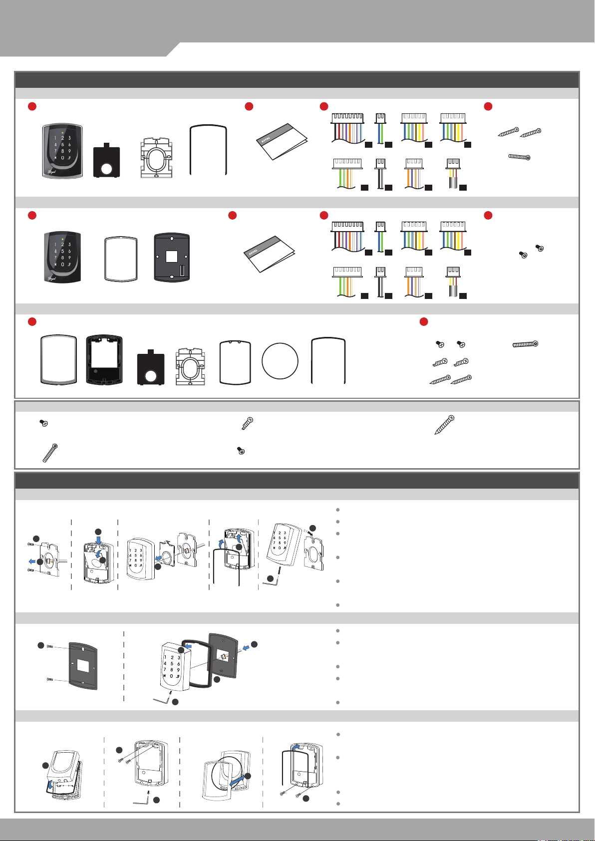
Products
®
AR-725E-M / AR-725E / AR-725X
2
User Guide
3
Terminal Cables
4
Tools
V090819
A.
AR-725E
1
Products
A1.
AR-725X
1
Products
A2. A3.
Parts Description
Button Head Pozidriv
a.
Tapping Screw: M3x10
d.
Security Torx Screw:
M3.5x15
P1
P2
P3
P4
c x2
d x1
B.
C.
D.
2
User Guide
3
P5
Terminal Cables
P1
P6
P2
P7
P3
P8
4
Tools
P4
e x2
E.
F.
P5
P6
P7
2
Tools
P8
a x2
d x1
b x2
c x2
B.
C. H.G. D.
b. c.
Button Head Pozidriv
Slotting Screw: 2.5x10
e.
Flat Head Hex Socket
Flat Head Cap Philips
Tapping Screw: 4x19.1
Screw: M3x8
Installation
AR-725E-M
2
C.
1
c.
AR-725E
1
AR-725X
A1.
1
G.
Pull the cables from the square access hole of the mounting plate C.
3
A.
A.
4
B.
B.
5
A.
C.
B.
A.
6
8
D.
g.
7
d.
Use a screwdriver to screw the metal plate C to the wall.
Take off the plastic mounting plate B from the body A, and pull the cables
C.
through the access hole of C and B, then connect to the body A.
Assemble plate B with the body A, and embed the water proof strip D
onto the plastic side frame.
Assemble the body A onto the mounting plate C with the Allen key and
screws (accessories supplied).
Turn on the power and LED will light and beep will sound.
E.
F.
A1.
F.
3
2
Use a screwdriver to screw the base F onto the wall.
Attach the water proof gasket to the body A1, and pull the cables
from the square hole of the base F, and connect to the body A1.
Assemble the body A1 with the base F.
4
e.
f.
5
Screw A1 and F tight with the Allen key and screws (accessories
supplied).
Turn on the power and LED will light and beep will sound.
Put on G, and attach A1 onto the plastic plate A3, and screw it with
the Allen key and screws (accessories supplied).
Put the ring O on the metal frame, and put them together onto the
reader A1+A3, and screw them and buckle up the 4 buckles on the
back.
Embed the water proof strip D onto the frame side of the base.
Following by the install process of AR-725E-M.
A3.
A2.
H.
A1.+A3.
2
b.
e.
3
f.
D.
4
a.
5
Page 2
3 Door Controller
Illuminated Touch-panel
Notice
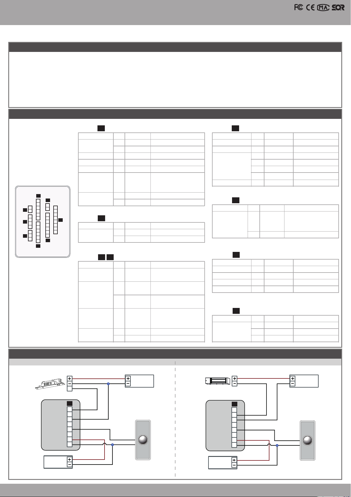
1. Tubing: The communication wires and power line should NOT be bound in the same conduit or tubing.
2. Cable selection: Use AWG 22-24 Shielded Twist Pair to avoid star wiring. Use CAT5 for TCP/IP connection.
3. Power supply: Don’t equip reader and lock with the same power supply. The power for reader may be unstable when the lock is activating, that may make the
reader malfunction. The standard installation: Door relay and lock use the same power supply, and reader use independent power supply.
4. Keypad lock: If 725E does not link [TCP / IP connection], the 725E keypad locks about 5 seconds after power transmission.Setting will work after
725E switches to stand-alone mode.
Connector Table
P1Cable: P5Cable:
Wire Application
Door Relay
Common-COM-Point
Door Sensor
Exit Switch
Alarm Relay
1
Blue White
2
Purple White
3
4
5
6
Color
White
Orange
Purple
Gray
Description
(N.O.)DC24V1Amp
(N.C.)DC24V1Amp
(COM)DC24V1Amp
Negative Trigger Input
Negative Trigger Input
Transistor Output
Max. 12V/100mA
Wire Application
Reservation
Reservation
TCP/IP Output
Reservation
Wire
(Open Collector Active Low)
P3
P2
6
5
2
2
P6
1
4
3
P7
2
1
3
2
P8
1
P4
8
4
1
7
3
6
2
7
5
1
6
P1
4
5
6
3
4
5
2
3
4
1
2
3
1
2
P5
1
Power
P2Cable:
Wire Application
RS-485 for Lift
Controller
P3 P4Cable:
Wire Application
Beeper
LED
7
8
Wire
1
2
Wire
1
2
3
Thick Red
Thick Black
Color
Thick Green
Thick Blue
Color
Pink
Yellow
Brown
DC 12V
DC 0V
Description
RS-485(B-)
RS-485(A+)
Description
Beeper Output
5V/100mA, Low
Red LED Output
5V/20mA, Max.
Green LED Output
P6Cable:
Wire Application
TTL Serial Port
P7Cable:
Wire Application
WGB Exit Switch
WGB Door Sensor
WGA Exit Switch
WGA Door Sensor
5V/20mA, Max.
Door Output
Wiegand
4
5
6
Blue White
Thin Green
Thin Blue
Transistor Output
Max. 12V/100mA
(Open Collector Active Low)
Wiegand DAT: 0 Input
Wiegand DAT: 1 Input
Wire Application
Anti-Tamper
Switch
P8Cable:
Wire
Wire
1
2
Wire
Wire
1
2
3
Orange White
4
5
Green White
6
7
Color
Black White
Black
1
Purple White
2
Orange White
3
4
1
2
3
Color
-
-
Description
Reservation
Reservation
Net - TX+
Orange
Net - TXNet - RX+
Green
-
Net - RXReservation
Description
Transistor Output
Max. 12V/100mA
(Open Collector Active Low)
GND
Color
Description
Negative Trigger Input
Negative Trigger Input
Purple
Orange
Color
Red
Orange
Yellow
Negative Trigger Input
Negative Trigger Input
Description
N.C.
COM
N.O.
V090819
Wiring Diagram
AR- 321H
Connect to Electric Bolt
Exit Switch
E
12V
GND
12V
GND
POWER
12VDC
Connect to Magnet Lock
Electric Bolt
P1
1
N.O.
2
3
COM
4
5
PB
6
7
12V
8
Controller Controller
GND
POWER
12VDC
12V
GND
N.O.
GND
EXIT
Push Button Push Button
Magnet Lock
N.C.
COM
PB
12V
GND
POWER
12VDC
P1
12V
GND
1
2
3
4
5
6
7
8
12V
GND
12V
GND
POWER
12VDC
N.O.
GND
EXIT
Page 3
SOYAL
ACCESS CONTROL SYSTEM
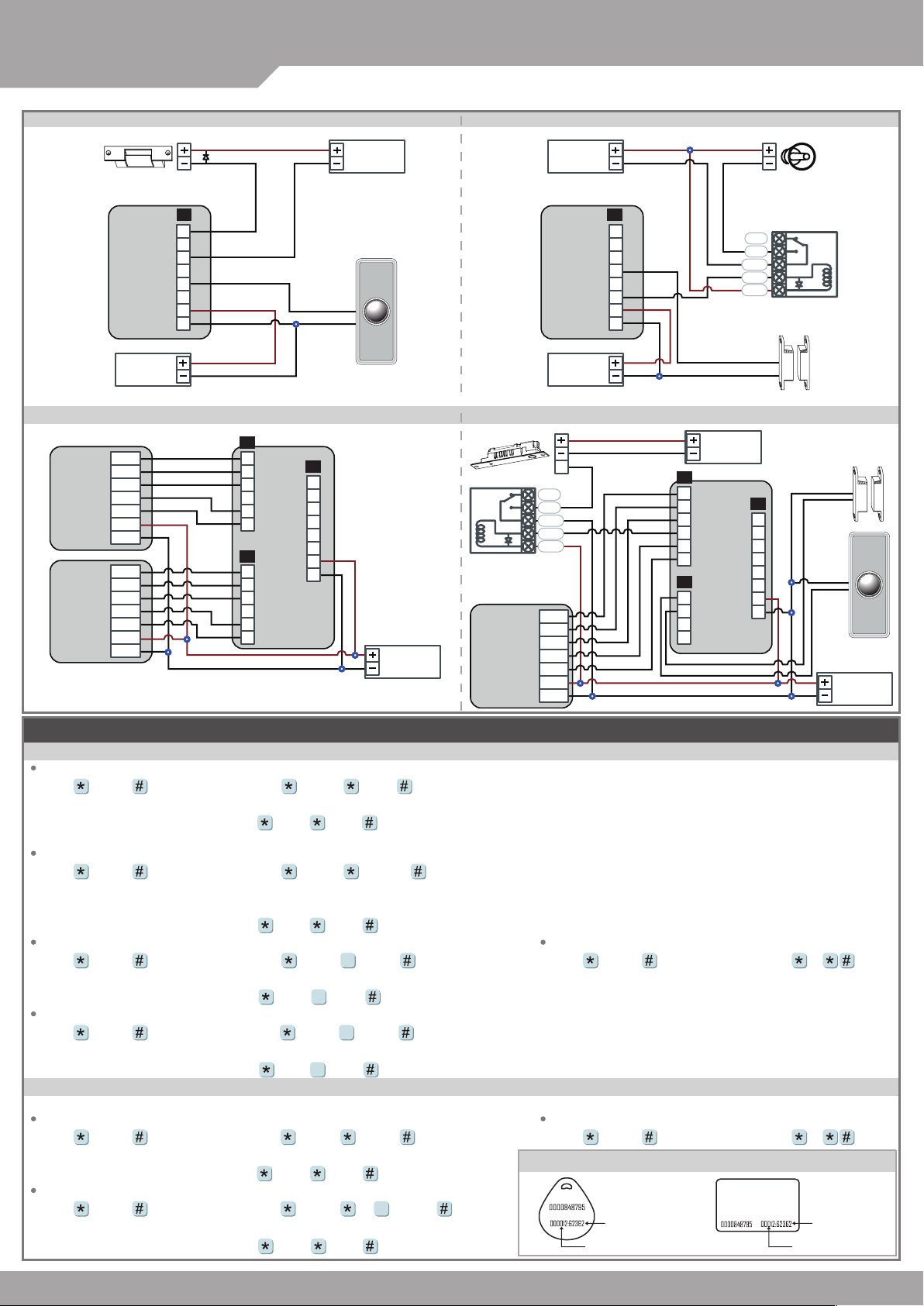
AR- 321H
Connect to Electric Strike
Electric Strike
1
N.O.
2
3
COM
4
5
PB
6
7
12V
8
Controller
AR- 321H
Connect to 2 Readers
Reader A
Reader B
GND
POWER
12VDC
BZ
RLED
GLED
WG 0
WG 1
12V
GND
BZ
RLED
GLED
WG 0
WG 1
12V
GND
®
GND
12V
GND
12V
AR-725E-M / AR-725E / AR-725X
Connect to Door Sensor
ALM
12V
GND
12V
GND
P1P1
1
2
3
4
5
6
7
8
12V
GND
POWER
12VDC
Controller
P3
BZ
1
RLED
2
GLED
3
Door Output
4
WG 0
5
WG 1
6
P7
PB-A
1
DS-A
2
PB-B
3
DS-B
4
P3
P4
1
2
3
4
5
6
1
2
3
4
5
6
BZ
RLED
GLED
WG 0
WG 1
BZ
RLED
GLED
WG 0
WG 1
12V
GND
N.O.
GND
Controller
P1
1
2
3
4
5
6
7
12V
8
GND
POWER
12VDC
EXIT
Push Button
POWER
12VDC
POWER
12VDC
Door Sensor
Controller
POWER
12VDC
Connect to Door Controller
12V
GND
Exit Switch
Electric Bolt
Relay Outpot
Module
Reader A
E
N.C.
N.O.
COM
CTL
12V
BZ
RLED
GLED
WG 0
WG 1
12V
GND
12V
GND
Alarm
N.C.
N.O.
COM
CTL
12V
Relay Outpot Module
Door Sensor
Door Sensor
P1
1
2
3
4
5
6
12V
7
GND
8
Push Button
V090819
EXIT
POWER
12VDC
Adding and Deleting Tag
Mode4/Mode8
AR- 321H
Adding the Single Tag or the Random tags
Input 123456 (or Master Code)
19 UUUUU 00001
→
Get Tag close to RF Area
→
[e.g.] User Address NO.100 and NO.101 have 2 pcs of random tags:
Access programming mode
P.S. The First ta g has now been added, p resent t he rest of t he tags one after t he other t o add them t o the system as well.
19 00100 00001
→
Get Tag close to RF Area
→
Adding the Sequential tags
Input 123456 (or Master Code)
(Memory loc ation nu mber)
OK
[e.g.] User Address NO.101 to NO.120 have 20 pcs of sequential tags:(62312~62332)
Access programming mode
19 UUUUU QQQQQ
→
19 00101 00120
→
Get Tag close to RF Area
→
Get Tag close to RF Area
→
:
Deleting the Single Tag
Input 123456 (or Master Code)
10 SSSSS EEEEE
→
9
[e.g.] Delete User Address: 00058
Access programming mode
10 00058 00058
→
9
Deleting a batch of Tags
Input 123456 (or Master Code)
10 SSSSS EEEEE
→
9
[e.g.] Delete User Address: 00101~00245
Access programming mode
10 00101 00245
→
9
Mode6
At the Mode 6, User Address = Card Code
※
Adding Tag
Input 123456 (or Master Code)
[e.g.] Add User Address: 00100~ 01254
Access programming mode
Deleting Tag
Input 123456 (or Master Code)
[e.g.] Delete a tag with card code 62362
Access programming mode
11 SSSSS EEEEE
→
11 00100 01254
→
10 SSSSS (or )EEEEE
→
10 62362 62362
→
→
9
→
→
OK
OK
OK
→
Tag Information
OK
(Present the tag to the cont roller.)
OK
→
(Present the tag w ith the lowest nu mber to t he cont roller.)
(only use th e tag NO. 62312)
→
→
OK
Deleting All Tags
Input 123456 (or Master Code)
Deleting All Tags
Input 123456 (or Master Code)
CARD CODE
SITE CODE
(Memory loc ation nu mber)
OK
29 29
→
29 29
→
CARD CODE
SITE CODE
→
Page 4

3 Door Controller
Illuminated Touch-panel
Programming
A. Entering and Exiting Programming Mode
Entering
Input 123456 or PPPPPP
[e.g.] The Default Value= 123456, if already changed the Master Code= 876112, input
Exiting
Input
Changing the Master Code
Access programming mode
[e.g.] If want to changing the Master Code= 876112, input
09 PPPPPPRRRRRR [Input the 6-digit new master code twice.]
→
12345 6
09 876112876112
→
B. Changing the Node ID of Reader
Access programming mode
[NNN= Node ID: 000~254; MMM=725E Door NO.:1~255; AAA=WGA Door NO.:1~255; BBB=WGB Door NO.:1~255]
00 NNN MMM AAA BBB
→
C.Setting up the control mode (M4/M6/M8)
Access programming mode
Mode Support
Networking/
M4
Stand-Alone
User
Capacity
16,000
(0~15,999)
04 N [N=4/6/8]
→
Access Mode
1.Card only
2.Card and PIN
3.Card or User address
(4-di git indi vidual PI N)
(4-di git PIN)
(5-digit)
+ Individual PIN
Auto- show
Duty time
87 6112
Event
Capacity
V
30,000
Access programming mode
→
120
Holidays
V
Duress
V
Time
Zone
unlimited
Lift
Control
64
V090819
Anti-pass-
back
V
Stand-Alone
M6
Networking/
M8
Stand-Alone
Mode 6 the number of users up to 65535, largely because of its read- only CARD CODE, unlike Mode4/Mode8 shall read the SITE CODE and CARD CODE.
※
65,535
(1~65535)
16,000
(0~15,999)
1.Card only
2.Card and PIN
3.Card or PIN
1.Card only
2.Card and PIN
3.Card or PIN
(4-di git publ ic PIN= A rming PWD)
(4-di git publ ic PIN= Duress code)
(4-di git indi vidual PI N)
(4-di git indi vidual PI N)
X
V
X
30,000
X
V
X
V
X
unlimited
X
64
D. Setting up the password
Individual PWD (M4/M8)
Card or PIN: Access programming mode
Card and PIN: Access programming mode
Public PWD (M6)
PIN only: Access programming mode
Card and PIN: Access programming mode
12 UUUUU PPPP [e.g. User address: 00001 and PWD: 1234. Input 12 00001 1234 ]
→
13 UUUUU PPPP [e.g. User address: 00001 and PWD: 1234. Input 13 00001 1234 ]
→
15 PPPP [Input 4- digit PWD, default value: 4321]
→
17 PPPP [Input 4-digit PWD, default value: 1234, disable PIN: 0000]
→
E. Anti-pass-back(M4/M8)
Usually, anti-pass-back is commonly applied to parking areas in order to prevent from multi-entr y with one card at a time, or somewhere wants to
monitor not only the access but also exit condition.
Enable device
Access programming mode
[e.g.] If the AR-725E set to exit reader, WGA set to access reader.
Access programming mode
Enable card user
Access programming mode
[e.g.] User address from 00152 to 00684 enable the anti-pass-back function: 26 00152 00684 0
20 U DDD [Please refer to function default value for details.]
→
20 0 128
→
26 SSSSS EEEEE N [N=0 Enable/ N=1 Disable/ N=2 Reset]
→
20 1 192 [Please refer to function default value for details.]
→
F. Auto Open Zone
Door will keep opening af ter rst man ashing card. When the reader is stand-alone, supporting only 16 sets of auto-open zone by device setting.
Auto-open zone can extend up to unlimited sets by Networking.
Enable/Disable auto open zone
Access programming mode
[e.g.] If the AR-725E set to Enable aut open zone.
Access programming mode
Enable/Disable auto open door without presenting card
Access programming mode
[e.g.] If the WG-B set to Enable aut open door without presenting card.
Access programming mode
Setting up access time
Access programming mode
NN: 16 sets of auto-open zone (NN=00~15)
HHMMhhmm=Starting time to ending time (e.g.: 08301200=08:30 to 12:00)
6543217H= 7 days of week + Holiday (Sat/Fri/ Thu/ Wed/Tue/Mon/Sun) (F= 0: disable; 1: enable)
20 U DDD [Please refer to function default value for details.]
→
20 0 004 [Please refer to function default value for details.]
→
24 U DDD [Please refer to function default value for details.]
→
24 2 128 [Please refer to function default value for details.]
→
08 U NN HHMMhhmm 6543217H
→
X
V
Page 5

®
AR-725E-M / AR-725E / AR-725X
SOYAL
ACCESS CONTROL SYSTEM
G. Lift control
Connect with AR-401RO16B to control which oors the user will be able to access. [BAUD9600]
Single oor
Access programming mode
UUUU=User Address LL=Floor number (01~64 oor/stop)
[e.g.] User address NO. 45 only can reach the elevator to the 24th oor: 27 00045 24
Multi oors
Access programming mode
[UUUUU=User address G: 8 sets of lift control (Input: 0~7) LLLLLLLL:
8 oors/stop setting (L=0=Disable, L=1=Enable)
[e.g.] User address NO. 168 can reach only the 6th and 20th oor:
Access programming mode
→ 21 00168 2 00001000
H. Setting Up the Arming
Conditions:
1. Arming is enabled
2.Alarm system connected
Enable Arming status:
Standby Mode
Card only
Enable all devices
Induct valid card → Input 4 digit
arming code
Enter Program Mode
Enable all devices: Access programming mode
Disable Arming status:
Standby Mode
Card only
Disable all devices
Induct valid card → Input 4 digit
arming code
There is NO arming mode for M6. Factory default armingcode is: 1234. U=Reader unit (0=725E, 1=WGA, 2=WGB).
※
Restoring Factory Settings
→
→
9
Reset all device parameters and user card data
Reset all device parameters and user card data:
Access programming mode
27 UUUUU LL
→
21 UUUUU G LLLLLLLL
→
21 00168 0 00100000
→
→ OK
Application:
1. Door open too long: Door is open longer than door relay time plus door close time.
2. Force open (Opened without a valid user card): Access by force or illegal procedure.
3. Door position abnormal: When power is off and then on, reader on arming bffore power off.
Enable particular device
Induct valid card → Input 4 digit
arming code → U
→
Disable particular device
Induct valid card → Input 4 digit
arming code → U
9
→ 29
29
Card or Passcode
Input 5 digit user address → Input 4
digit pass code
arming code
Enable particular device: Access programming mode
Card or Passcode
Input 5 digit user address → Input 4
digit pass code
arming code
→ →
→
→ →
→
Please refer to below oor chart
Set
Floor/ Stop
(G)
L
L
8
Input 4 digits
or U
Input 4 digits
9
or U
0
1
2
3
4
5
6
7
7
16
15
24
23
32
31
40
39
48
47
56
55
64
63
Card and Passcode
Induct valid card → Input 4 digit pass
code → → Input 4 digits arming
code
Card and Passcode
Induct valid card → Input 4 digit pass
code → → Input 4 digits arming
code
14
22
30
38
46
54
62
→
→
V090819
L
L
L
L
L
L
6
5
4
3
2
1
13
12
11
10
9
21
20
19
18
17
29
28
27
26
25
37
36
35
34
33
45
44
43
42
41
53
52
51
50
49
61
60
59
58
57
or U
→
9
or U
U
Reset all user card data:
Access programming mode
Reset IP Setting:
Press “IP Resent Button” of main board for few seconds
Appendix-Firmware Upgrade
→ 29
29
Get the upgrade software from SOYAL or our distributor and run “UdpUpdater” software
Execute the sof tware
The software is within SOYAL CD or Login the
SOYAL web to downloads
Update the rmware
[Please login the SOYAL web to download the new ISP Firmware.]
1. Input the Target Address and Port
2. [Load Fide] open the documents that have the new ISP Firmware
3. Click the new ISP Firmware and [Open] it
4. Click [Update Device] to start the rmware update
5. Till the screen shown [Program Completed]
1
5
4
2
3
Page 6

IP Setting
Turn on your Web Browser and input factory default IP
address: http://192.168.1.127
If the AR-725E of the IP address
has changed We must enter the
new IP address.
Page menu
Monitor the on-line computer
IP Setting
Change the Log-in information
3 Door Controller
Illuminated Touch-panel
V090819
Current State
Online Status is able to monitor and show which computer is linking on
Ethernet Module
Show which computer is li nking
on Ethernet Module.
Current IP address of the AR-725E.
Log-in User Password
When you choose the "Networking Setting" or "User Password" at rst.
Log-in window will pop out and please input
At the Factory Default
※
User name: admin
Password: No as default value,so please just press “OK” to log-in
Networking Setting
You will nd initial IP Address 192.168.1.127 and check
MAC Address is the same as sticker on Ethernet Module
device. Please revise IP address you want, and then click
“Update” button. After updating the IP, please re-connect
the Web Browser by new IP address.
adminadmin
After changed and updated IP to
new address, re-connect the Web
Browser by new IP address.
User Password
Change the log-in password to lock the IP setting of
Ethernet Module.
The password composes of 10 characters at most, it can be
either A~Z or 0~9.
Max. 10 characters allowed
(Composed of A~Z and 0~9)
Page 7

SOYAL
ACCESS CONTROL SYSTEM
Command List
Function
Entering programming mode
Exiting programming mode
Exiting programming mode and
enabling all device into arming
status. (Including 725E, WGA
and WGB)
Exiting programming mode and
enabling each device into arming
status. (725E, WGA or WGB)
Node ID setting
Door relay time setting
Alarm relay time setting
Control mode setting
Arming delay time setting
Alarm delay time setting
Master card setting
(For entering programming mode
instead of pressing master code)
Auto-open zone setting
Master code settings
Suspend or delete tags
M4/8: Recover tag
M6: Setting up a batch of users
to access by card only
Setting up the PWD/PIN
Setting up the PWD/PIN
Arming output setting
M4/M8: Duress code setting
M6: Public PIN setting
(Card or PIN)
M4/M8: Arming PWD setting
M6: Public PIN setting
(Card and PIN)
Enabling or Disabling into arming
status
Enabling or Disabling target unit
into arming status
Enabling all units into arming
status
Disabling all units into arming
status
®
AR-725E-M / AR-725E / AR-725X
Command
PPPPPP
U
00 NNN MMM AAA BBB
02 U TTT
03 TTT
04 N
05 TTT
06 TTT
07 SSSSS EEEEE
08 U NN HHMMhhmm
6543217H
09 PPPPPPRRRRRR
Suspend= 10 SSSSS EEEEE
Delete= 10 SSSSS EEEEE
11 SSSSS EEEEE
11 SSSSS EEEEE
12 UUUUU PPPP
13 UUUUU PPPP
14 TTT
15 PPPP
17 PPPP
Flashing a valid card and input
NNNN
Flashing a valid card an input
NNNN U
Flashing a valid card and input
NNNN
Flashing a valid card and input
NNNN
9
9
Exposition
PPPPPP: Master Code, (Default value: 123456)
U= Enable target unit (0=725E, 1=WGA, 2=WGB)
NNN= Node ID of 725E: 001~254; MMM= Door number of 725E
AAA= Door number of WGA; BBB= Door number of WGB
U= Enable target unit (0=725E, 1=WGA, 2=WGB)
TTT= Door relay time
(Input 000=Normal open / Input 001~600=1~600 sec. /
Input 601~609=0.1~0.9 sec. )
TTT= Door relay time
(Input 000=Normal open / Input 001~600=1~600 sec.)
N= Mode: 4/6/8
Base on second, range: 001~255
Base on second, range: 001~255
Input a user or a batch of user as the master card: 00000~15999
SSSSS= starting user address; EEEEE= ending user address
U= Enable target unit (0=725E, 1=WGA, 2=WGB)
NN: 16 sets of auto-open zone (Range: 00~15)
HHMMhhmm=staring time to ending time
(e.g.: 08301200=08:30 to 12:00)
6543217: 7 days of week -Sat/Fri/Thu/Wed/Tue/Mon/Sun
(Input value: 0=disable; 1=enable)
H: Holiday (Input value: 0=disable; 1=enable)
PPPPPP= New master code
RRRRRR= Repeat the new master code
= Suspend; = Delete
SSSSS= starting user address; EEEEE= ending user address
Recover the paused tag
SSSSS=starting Card Code; EEEEE= ending Card Code
UUUUU= user address; PPPP=4-digit individual PWD
(Access mode: Card or PIN)
UUUUU= user address; PPPP=4-digit individual PWD
(Access mode: Card and PIN)
Base on 1ms, range:1~255, default value=10, Input 0= Timeless
PPPP=4-digit PWD
(P.S. Duress code will be unavailable and as public PIN at
access mode “Card or PIN” of M6)
(Default value=4321; disable PIN=0000)
PPPP=4-digit PWD
(Default value=1234; disable PIN=0000)
NNNN=4-digit arming PWD
U=Enable target unit (0=725E, 1=WGA, 2=WGB)
9
V090819
Mode
M4/M6/M8
M4/M6/M8
M4/M6/M8
M4/M6/M8
M4/M8
M4/M6/M8
M4/M6/M8
M4/M6/M8
M4/M6/M8
M4/M6/M8
M4/M8
M4/M6/M8
M4/M6/M8
M4/M6/M8
M4/M8
M6
M4/M8
M4/M8
M4/M6/M8
M4/M8
M6
M4/M8
M6
M4/M6/M8
Page 8

3 Door Controller
Illuminated Touch-panel
V090819
Function
Door close time
Adding tags by induct
Factory setting-1
Lift control setting: multi-doors
Add/Delete tags by closing tags
into RF area (M6 only)
AR-401RO16/ AR-401RO16B
relay time setting
Factory setting-2
Real time clock setting
Anti-pass-back
(Enable user)
Lift control setting: single door
Duress Function and Arming
output setting
Delete all tag
Same tag reading interval time
Auto ring the clock alarm
schedule
Holiday Setting
Function Default Value
Command
18 TTT
19 UUUUU QQQQQ
20 U DDD
21 UUUUU G LLLLLLLL
22 N
23 MMM TTT
24 U DDD
25 YYMMDDHHMMSS
26 SSSSS EEEEE P
27 UUUUU LL
28 FFF
29 29
31 TTTT
32 SS HHMMTT 6543217H
35 MMDD F
Exposition
Base on second, range: 000~255, default value: 15 sec.
UUUUU= User address; QQQQQ= the amount of card
U=Enable target unit (0=725E, 1=WGA, 2=WGB)
DDD=Function default value
(Please refer to function default value for details)
UUUUU=User address
G: 8 groups of lift control (Input range: 0~7)
LLLLLLLL: 8 oors/stop setting (0=Disable, 1=Enable)
N=0=Delete tag; N=1=Add tag
Close tag into RF area one by one.
MMM= Node ID of lift controller
TTT= relay time: 000~600=1~600 sec.
U= Enable target unit (0=725E, 1=WGA, 2=WGB)
DDD= Function default value
(Please refer to function default value for details)
YYMMDDHHmmSS: Year/Month/Day/Hour/Min./Sec.
SSSSS=starting user address; EEEEE=ending user address
P=0=Enable; P=1=Disable; P=2=Initial
UUUUU=User Address; LL=Floor number (01~63 oor/stop)
Arming output: FFF= 008 (default value)
Duress Function: FFF= 000
Base on 10ms, range from 0 to 6000
SS= 16 sets auto alarm schedule, range 0~15
HHMM= HH:MM (ex. 0830: Ring bell at 08:30)
TT=Period of time to ring bell
(Base on second, range 01~99 sec.)
6543217: 7 days of week -Sat/Fri/Thu/Wed/Tue/Mon/Sun
(Input value: 0=disable; 1=enable)
H: Holiday (Input value: 0=disable; 1=enable)
MM= Month of year (01=Jan...10=Oct.)
DD= Date of month (01=1st day of month)
F= 0:Del; 1: Add
20 U DDD
Function Option Value Application
Time Attendance
Auto Re-lock
Auto Open
When Access Mode is "Card and PIN", Readers can skip pressing PIN code.
Exit by Push Button
Enable force Open
As Access/Exit Reader
Anti-pass-back
[e.g.] DDD value of AR-725E to Enable "Auto Open" + "Exit by Push Button" + "Anti-pass-back" =004+016+128= 148
As a result of that, the command will be 20 0 148
0: Yes
※
0: Disable
※
0: Disable
※
0: Disable
※
0: Disable
0: Slave
※
0: Exit
※
0: Disable
※
1: No
1: Enable
1: Enable
1: Enable
1: Enable
※
1: Mater
1: Access
1: Enable
Networking
001
Networking/Stand-Alone
002
Networking/Stand-Alone
004
Networking/Stand-Alone
008
Networking/Stand-Alone
016
Networking
032
Networking
064
Networking
128
Default Value
※
Mode
M4/M6/M8
M4/M8
M4/M6/M8
M4/M8
M6
M4/M8
M4/M6/M8
M4/M6/M8
M4/M8
M4/M8
M4/M6/M8
M4/M6/M8
M4/M6/M8
M4/M6/M8
M4/M8
24 U DDD
Function Option Value Application
Stop Alarm by...
Open door immediately without 1st card presented at auto open zone.
U = Enable target unit (0=725E, 1=WGA, 2=WGB); DDD = Value
※
0: None
※
0: Disable
※
1: Push button/
Door Closed
1: Enable
Networking/Stand-Alone
064
Networking/Stand-Alone
128
http://www.soyal.com
SOYAL
To have more detailed information, E-learning, and Q&A, please visits our website.
Thanks for You
Default Value
※
 Loading...