

Page 1
SOYAL
Copyright by SOYAL Technology Co., Ltd.. All rights reserved.
ACCESS CONTROL SYSTEM
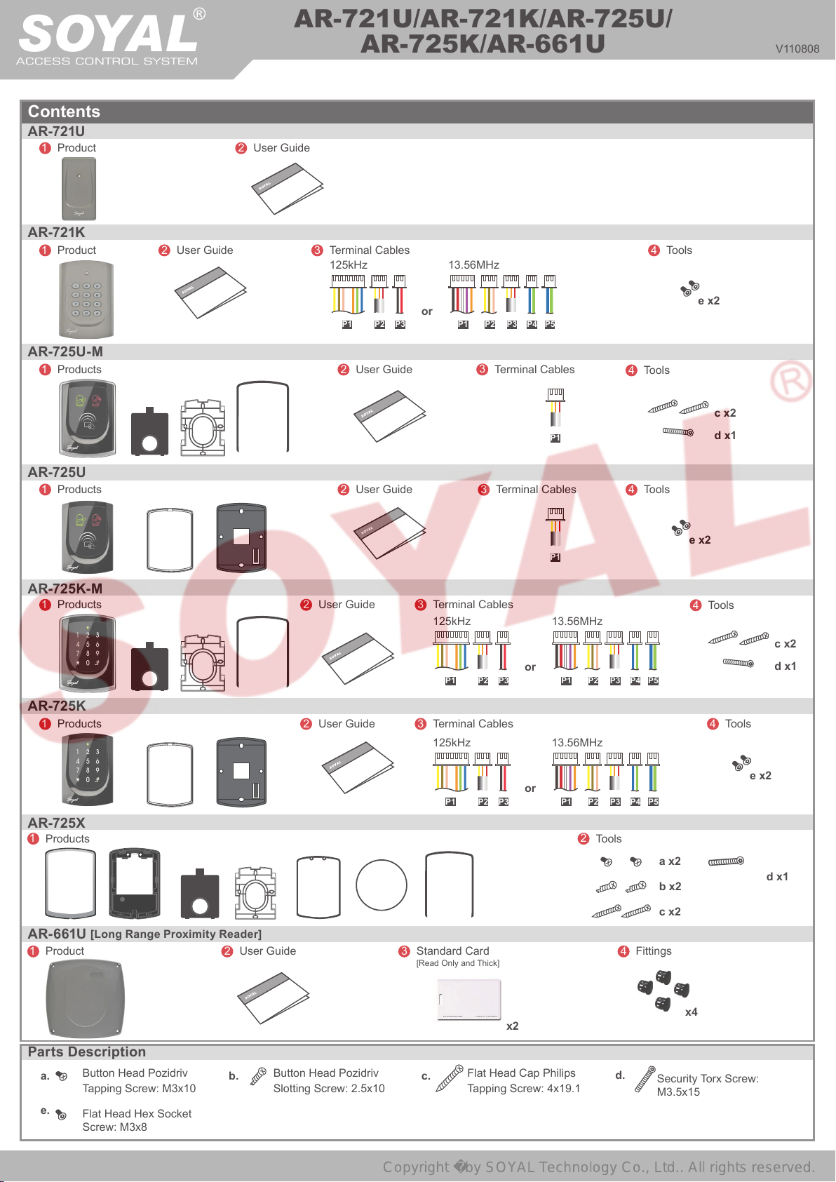
Contents
AR-721U
1
Product
AR-721K
1
Product
2
User Guide
®
2
User Guide
AR-721U/AR-721K/AR-725U/
AR-725K/AR-661U
3
Terminal Cables
125kHz
13.56MHz
4
V110808
Tools
AR-725U- M
1
Products
AR-725U
1
Products
AR-725K- M
1
Products
AR-725K
1
Products
2
User Guide
2
User Guide
P1 P2 P3
2
User Guide
2
User Guide
or
P1 P2 P3 P4 P5
3
Terminal Cables
125kHz
P1 P2 P3
3
Terminal Cables
125kHz
3
Terminal Cables
3
Terminal Cables
or
P1
P1
13.56MHz
P1 P2 P3 P4 P5
13.56MHz
e x2
4
Tools
c x2
d x1
4
Tools
e x2
4
Tools
c x2
d x1
4
Tools
AR-725X
1
Products
AR-661U
1
Product
[Long Range Proximity Reader]
Parts Description
Button Head Pozidriv
a.
Tapping Screw: M3x10
e.
Flat Head Hex Socket
Screw: M3x8
2
User Guide
b. c.
Button Head Pozidriv
Slotting Screw: 2.5x10
3
P1 P2 P3
Standard Card
[Read Only and Thick]
Flat Head Cap Philips
Tapping Screw: 4x19.1
x2
or
P1 P2 P3 P4 P5
e x2
2
Tools
a x2
b x2
c x2
4
Fittings
d.
Security Torx Screw:
M3.5x15
x4
d x1
Page 2
Access Reader
Copyright by SOYAL Technology Co., Ltd.. All rights reserved.
125kHz / 13.56MHz
V110808
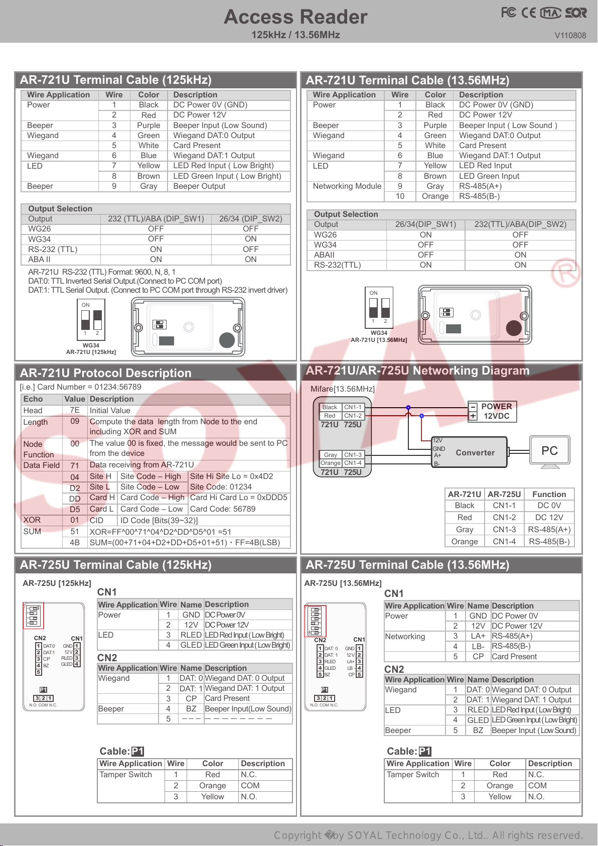
AR-721U Terminal Cable (125kHz)
Wire Application
Power
Beeper
Wiegand
Wiegand
LED
Beeper
Wire
Color
1
Black
2
Red
3
Purple
4
Green
5
White
6
Blue
7
Yellow
8
Brown
9
Gray
Output Selection
Output
232 (TTL)/ABA (DIP_SW1)
WG26
WG34
RS-232 (TTL)
ABA II
AR-721U RS-232 (TTL) Format: 9600, N, 8, 1
DAT:0: TTL Inverted Serial Output.(Connect to PC COM port)
DAT:1: TTL Serial Output. (Connect to PC COM port through RS-232 invert driver)
1ON2
WG34
AR-721U [125kHz]
Description
DC Power 0V (GND)
DC Power 12V
Beeper Input (Low Sound)
Wiegand DAT:0 Output
Card Present
Wiegand DAT:1 Output
LED Red Input ( Low Bright)
LED Green Input ( Low Bright)
Beeper Output
26/34 (DIP_SW2)
OFF
OFF
ON
ON
2
1
ON
OFF
ON
OFF
ON
AR-721U Protocol Description
[i.e.] Card Number = 01234:56789
Description
Echo
Head
Length
Node
Function
Data Field
XOR
SUM
Value
7E
Initial Value
09
Compute the data length from Node to the end
including XOR and SUM
The value 00 is xed, the message would be sent to PC
00
from the device
Data receiving from AR-721U
71
Site H
04
Site L
D2
Card H
DD
Card L
D5
01
CID
51
XOR=FF^00^71^04^D2^DD^D5^01 =51
4B
SUM=(00+71+04+D2+DD+D5+01+51)‧FF=4B(LSB)
Site Code – High
Site Code – Low
Card Code – High
Card Code – Low
ID Code [Bits(39~32)]
Site Hi Site Lo = 0x4D2
Site Code: 01234
Card Hi Card Lo = 0xDDD5
Card Code: 56789
AR-721U Terminal Cable (13.56MHz)
Wire Application
Power
Beeper
Wiegand
Wiegand
LED
Networking Module
Output Selection
Output
WG26
WG34
ABAII
RS-232(TTL)
1ON2
WG34
AR-721U [13.56MHz]
Wire
10
Color
1
Black
2
3
4
5
6
7
8
9
Red
Purple
Green
White
Blue
Yellow
Brown
Gray
Orange
26/34(DIP_SW1)
ON
OFF
OFF
ON
Description
DC Power 0V (GND)
DC Power 12V
Beeper Input ( Low Sound )
Wiegand DAT:0 Output
Card Present
Wiegand DAT:1 Output
LED Red Input
LED Green Input
RS-485(A+)
RS-485(B-)
232(TTL)/ABA(DIP_SW2)
OFF
OFF
ON
ON
2
1
ON
AR-721U/AR-725U Networking Diagram
Mifare[13.56MHz]
Converter
Black
Red
Gray
Orange
POWER
12VDC
CN1-1
CN1-2
CN1-3
CN1-4
Black
Red
721U
Gray
Orange
721U
CN1-1
CN1-2
725U
CN1-3
CN1-4
725U
12V
GND
A+
B-
FunctionAR-721U AR-725U
DC 0V
DC 12V
RS-485(A+)
RS-485(B-)
AR-725U Terminal Cable (125kHz)
AR-725U Terminal Cable (13.56MHz)
AR-725U [125kHz] AR-725U [13.56MHz]
CN1
ON
1
2 3 4
Wire Application
Power
Wire
1
2
3
4
Wire
1
2
3
4
N.O.
CN2
1
2
3
4
5
3
P1
COM
DAT:0
DAT:1
CP
BZ
LED
CN1
1
GND
2
12 V
3
RLED
GLED
CN2
4
Wire Application
Wiegand
12
N.C.
Beeper
5
Description
Name
DC Power 0V
GND
DC Power 12V
12V
LED Red Input ( Low Bright)
RLED
LED Green Input ( Low Bright)
GLED
Description
Name
Wiegand DAT: 0 Output
DAT: 0
Wiegand DAT: 1 Output
DAT: 1
Card Present
CP
Beeper Input(Low Sound)
BZ
ON
N.O.
CN2
3
1
2
3
4
5
2 3 456
1
P1
COM
DAT: 0
DAT: 1
RLED
GLED
BZ
12
CN1
GND
1
12 V
2
LA+
3
LB -
4
CP
5
N.C.
P1Cable:
Wire Application
Tamper Switch
Wire
1
2
3
Color
Red
Orange
Yellow
Description
N.C.
COM
N.O.
CN1
Wire Application
Power
Networking
CN2
Wire Application
Wiegand
LED
Beeper
P1Cable:
Wire Application
Tamper Switch
Wire
1
2
3
4
5
Wire
1
2
3
4
5
Wire
Name
Name
DAT: 0
DAT: 1
RLED
GLED
1
2
3
Description
DC Power 0V
GND
DC Power 12V
12V
RS-485(A+)
LA+
RS-485(B-)
LB-
Card Present
CP
Description
Wiegand DAT: 0 Output
Wiegand DAT: 1 Output
LED Red Input ( Low Bright)
LED Green Input ( Low Bright)
Beeper Input ( Low Sound)
BZ
Color
Red
Orange
Yellow
Description
N.C.
COM
N.O.
Page 3

SOYAL
Copyright by SOYAL Technology Co., Ltd.. All rights reserved.
ACCESS CONTROL SYSTEM
®
AR-721U/AR-721K/AR-725U/
AR-725K/AR-661U
V110808
AR-725U Terminal Cable (125kHz)
Dip-switch
D1 D2
ON
2 3 4
1
Output format
D1
D1
ABA_II / OMRON
WG-38
WG-34
WG-26
Indicator while
D2
D2
card present
Red LED On
Green LED On
Red LED & Beep On
No LED or Beep sound
DIP_SW1
DIP_SW1
ON
ON
OFF
OFF
ON
ON
OFF
OFF
DIP_SW3
DIP_SW3
ON
ON
OFF
OFF
ON
ON
OFF
OFF
DIP_SW2
DIP_SW2
ON
ON
ON
ON
OFF
OFF
OFF
OFF
DIP_SW4
DIP_SW4
ON
ON
ON
ON
OFF
OFF
OFF
OFF
AR-661U Terminal Cable (125kHz only)
Installation Notice
=200cm
R
Minimum distance between AR-661U & other proximity reader should
※
be over 200cm; otherwise, both readers might interfere each other.
AR-725U Terminal Cable (13.56MHz)
Dip-switch
D1 D2 D3
ON
Output format
D1
D1
WG-26
WG-34
ABA_II
1
2
3
4
5
6
7
8
9
RS-232(TTL)
DIP_SW4
OFF
ON
Red
Blue
Gray
Description
DC 0V (GND)
DC 12V~18V
Beeper Output
Wiegand DAT:0
Card Present
Wiegand DAT:1
SET1
SET2
SET3
Color
Black
Purple
Green
White
Yellow
Brown
D3
D3
725UD
725UD
725UD_M
725UD_M
2 3 45 6
1
D2
D2
Open RS-485
Open RFID_SIM
Wire Application
Power
Beeper
Wiegand
Wiegand
Output Selection
DIP_SW3
DIP_SW3
ON
ON
OFF
OFF
Wire
Output Selection
Output
SET 1
SET 2
Note:
※
WG26
Open
Open
WG34
Short to GND
Open
WG34+4: Follow 0101 after WG34 data stream for reader
identication.
DIP_SW1
DIP_SW1
ON
ON
OFF
OFF
OFF
OFF
ON
ON
DIP_SW5
DIP_SW5
RS-232 (TTL)
Open
Short to GND
OFF
OFF
ON
ON
Remark
regulated
Open collected
Open collected
Reserve
DIP_SW2
DIP_SW2
OFF
OFF
OFF
OFF
ON
ON
ON
ON
DIP_SW6
DIP_SW6
OFF
OFF
ON
ON
WG34 + 4
Short to GND
Short to GND
AR-661U Installation
721H with 2 pcs of 661U for two-door anti-pass-back Improvement of RF interference for 2 pcs of 661U
Single Reader (RF always ON)
Cable
Blue
Green
Purple
---
---
(RF switching)
GNDRF SYNL
AAR-721UB
FunctionPIN
Blue
Green
Pink
Brown
Yellow
Slaver
DAT: 1
DAT: 0
BEEP
G-LED
R-LED
1
2
3
4
5
6
Master
WG 34 + 4
7
8
9
1
2
POWER
12VDC
1
2
3
4
5
6
Slaver
WG 34
AR-721U/AR-725U/AR-661U Diagram
7
8
9
Controller
Readers
721U 725U 661U
Blue
Green
Purple
Brown
Yellow
Red
Black
EM
CN2-2
CN2-1
CN2-4
CN1-4
CN1-3
CN1-2
CN1-1
CN2-2
CN2-1
CN2-5
CN2-4
CN2-3
CN1-2
CN1-1
Blue
Green
Purple
Red
Black
B
Mifare
POWER
12VDC
12V
GND
WG 0
WG 1
Controller
A
WG 1
1
WG 0
2
BZ
3
GLED
4
RLED
5
1
2
Two AR-661U Readers Wiring
GNDRF SYNLGND RF SYNL
Output
Master
When the distance between two AR-661U readers is less than 6m
※
(recommended value), the sensing distance will be shortened. However,
you can use this method to avoid interference.
1
12V
2
GND
No 661U needs to connect to LED
※
AR-725UB AR-661UB
Mifare
EM
Blue
Green
Purple
Brown
Yellow
CN2-2
CN2-1
CN2-4
CN1-4
CN1-3
CN2-2
CN2-1
CN2-5
CN2-4
CN2-3
Page 4

721K/725K Terminal Cable (125kHz)
Copyright by SOYAL Technology Co., Ltd.. All rights reserved.
P1Cable:
Wire Application
Wiegand / ABA
Beeper
LED
P2Cable:
Wire Application
Tamper Switch
P3Cable:
Wire Application
Power
Wiegand Output Format
Output Format
Wiegand 26 Bit
Wiegand 34 Bit
RS-232
Magnetic ( ABA 8 Digital )
Magnetic( ABA 10 Digital )
Wire
1
2
3
4
5
6
7
Wire
1
2
3
Wire
1
2
Color
Thin Blue
Thin Green
Orange
Pink
Brown
Yellow
Color
Red
Orange
Yellow
Color
Thick Red
Thick Black
WG J2
Description
Wiegand DAT: 1 Input
ABA Format: Clock
Wiegand DAT: 0 Input
ABA Format: Data
ABA Format: Card Present
No Connection
Beeper Input (Low Sound)
LED Green Input (Low Bright)
LED Red Input (Low Bright)
Description
N.C.
COM
N.O.
Description
DC Power 12V
DC Power 0V
Open
Open
Short
Short
Short
Open
Open
Open
Open
Open
Access Reader
125kHz / 13.56MHz
EM(125kHz)
721K/725K[125kHz]
RLED
GLED
ABA
WG 0
P3
WG 1
12V
1
GND
2
POWER
12VDC
Cable position is showed in the Terminal Cable
※
RST/Bits
Open
Short
Open
Short
Open
Z
B
7
6
5
4
3
2
1
3
2
1
Tag Format
721K
P1
J1
G
W
J2
J3
P3
Output
Format
1
2
P2
T/B
its
S
R
BZ
P1
7
6
5
4
3
2
1
Output Format
1234567
P2
1 2 3
V110808
5-PIN
Connector
5
4
3
2
1
RLED
GLED
BZ
WG 0
WG 1
12V
GND
1
2
3
4
8-PIN
5
Connector
6
7
8
Controller
J3
J2
J1
ST
R
its
/B
725K
G
W
P1
Tag Format
Z
B
P3
2 1
Tag Format
SOYAL Format
EM Format [Default]
J3
Short
Open
721K/725K Terminal Cable (13.56MHz)
P1Cable:
Wire Application
Output Format
Power
P2Cable:
Wire Application
Beeper
LED
P3Cable:
Wire Application
Tamper Switch
P4Cable:
Wire Application
2-PIN Connector
Wiegand
P5Cable:
Wire Application
Networking
Module
Wire
1
2
3
4
5
Wire
1
2
3
Wire
1
2
3
Wire
1
2
Wire
1
2
Color
Orange
Purple
White
Thick Red
Thick Black
Color
Pink
Brown
Yellow
Color
Red
Orange
Yellow
Color
Thin Green
Thin Blue
Color
Thick Green
Thick Blue
Description
SET2
SET1
ABA Format / Reading card
DC 12V
DC 0V (GND)
Description
Beeper Input (Input Low)
LED Green Input (Input Low)
LED Red Input (Input Low)
Description
N.C.
COM
N.O.
Description
WG DAT:0 Output
ABA Format: Data
WG DAT:1 Input
ABA Format: Clock
Description
RS-485 (B-)
RS-485 (A+)
AR-721K [125kHz]
AR-725K
[125kHz]
Mifare(13.56MHz)
721K/725K[13.56MHz]
P2
RLED
3
GLED
2
BZ
P1
SET 2
SET 1
CP
12V
GND
1
1
WG 1
2
2
WG 0
1
3
P4
4
5
POWER
12VDC
Cable position is showed in the Terminal Cable
※
Output Format
Output Format
WG-26
WG-34
ABA-10
ABA-5-5
BZ
1
GLED
2
P2
RLED
3
P3
WG0
WG1
1
2
[13.56MHz]
123
AR-721K
P4
SET 2
SET 1
CP
V+
V-
SET 1
Open
Open
Short to GND
Short to GND
1
2
3
P1
4
5
1
P5
P3
2
AR-725K
1
2
3
P5
12
P4
12
WG0
WG1
SET 2
12345
SET 2
Open
Short to GND
Open
Short to GND
P2
123
BZ
GLED
RLED
SET 1
CP
V+
V-
P1
[13.56MHz]
5-PIN
Connector
P1
RLED
5
GLED
4
BZ
3
WG 1
2
WG 0
1
12V
GND
Controller
Note
Hex
Hex
BCD 10
BCD 5:5
1
2
3
4
8-PIN
5
Connector
6
7
8
SET 2
SET 1
GND
 Loading...