

Soyal AR-725, AR-725 E-V2 Owner's Manual
SOYAL
ACCESS CONTROL SYSTEM
®
AR-725 (E-V2)
V130116
a.
d.
e.
A.
A1.
A2. A3.
B.
E.
B.
C.
F.
C. H.G. D.
D.
b. c.
d x1
b x2
a x2
c x2
e x2
d x1
c x2
2
C.
1
c.
A.
B.
3
4
5
A.
B.
C.
6
A.
B.
D.
7
8
A.
C.
g.
d.
F.
1
f.
A1.
F.
E.
2
4
5
e.
3
A3.
A1.
G.
1
f.
2
3
e.
b.
A2.
A1.+A3.
H.
4
5
a.
D.
P1 P2 P3
P4 P5 P6 P7
※
P1 P2 P3
P4 P5 P6
P7
※
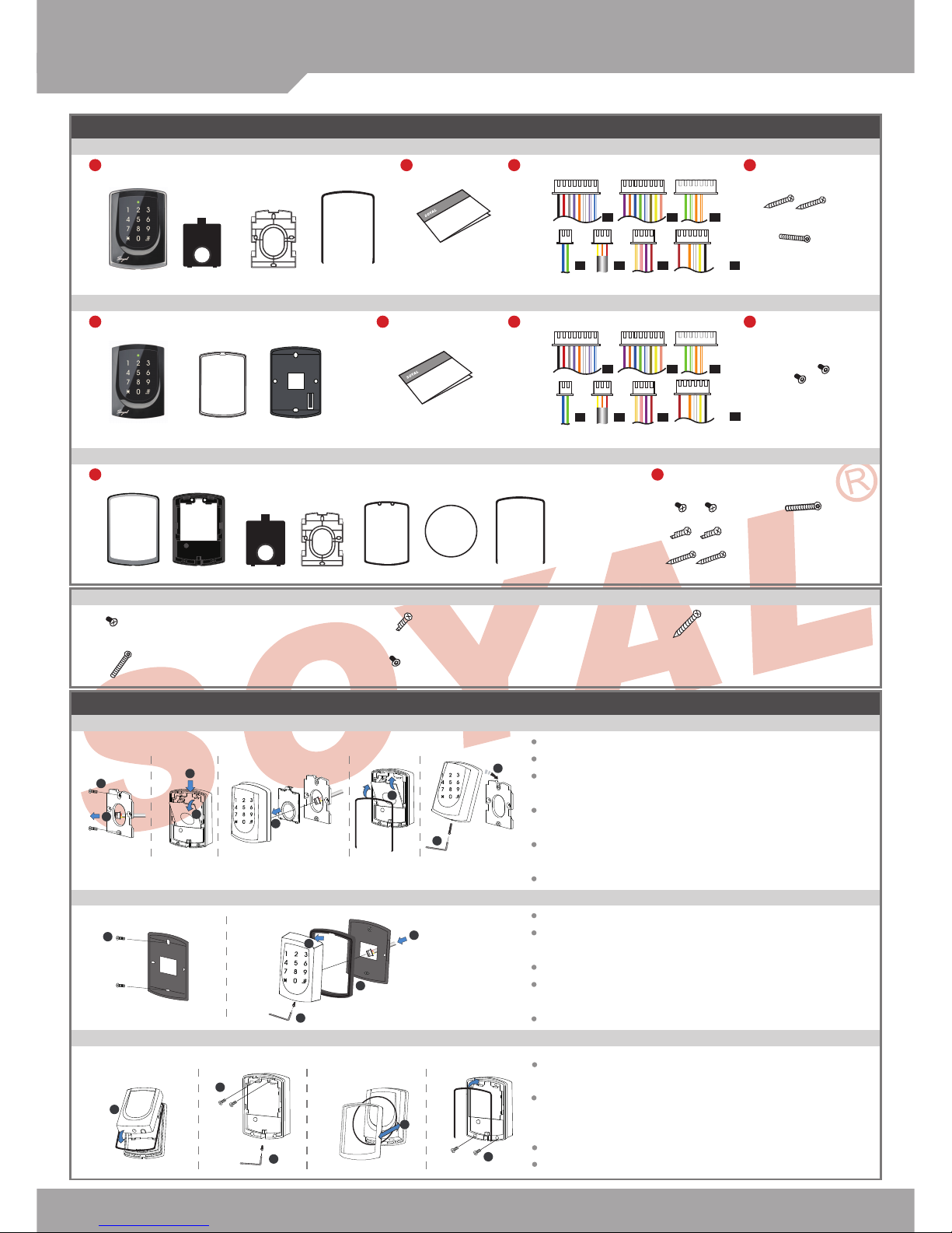
Contents
AR-725 (E-V2-M)
AR-725 (E-V2)
AR-725 (X)
1
Products
1
Products
1
Products
2
User Guide
2
User Guide
3
Terminal Cables
3
Terminal Cables
4
Tools
4
Tools
2
Tools
Pull the cables from the square access hole of the mounting plate C.
Use a screwdriver to screw the metal plate C to the wall.
Take off the plastic mounting plate B from the body A, and pull the cables
through the access hole of C and B, then connect to the body A.
Assemble plate B with the body A, and embed the water proof strip D
onto the plastic side frame.
Assemble the body A onto the mounting plate C with the Allen key and
screws (accessories supplied).
Turn on the power and LED will light and beep will sound.
Use a screwdriver to screw the base F onto the wall.
Attach the water proof gasket to the body A1, and pull the cables
from the square hole of the base F, and connect to the body A1.
Assemble the body A1 with the base F.
Screw A1 and F tight with the Allen key and screws (accessories
supplied).
Turn on the power and LED will light and beep will sound.
Put on G, and attach A1 onto the plastic plate A3, and screw it with
the Allen key and screws (accessories supplied).
Put the ring O on the metal frame, and put them together onto the
reader A1+A3, and screw them and buckle up the 4 buckles on the
back.
Embed the water proof strip D onto the frame side of the base.
Following by the install process of AR-725 (E-V2-M).
Button Head Pozidriv
Tapping Screw: M3x10
Security Torx Screw:
M3.5x15
Flat Head Cap Philips
Tapping Screw: 4x19.1
Button Head Pozidriv
Slotting Screw: 2.5x10
Flat Head Hex Socket
Screw: M3x8
Installation
AR-725 (E-V2-M)
AR-725 (E-V2)
AR-725 (X)
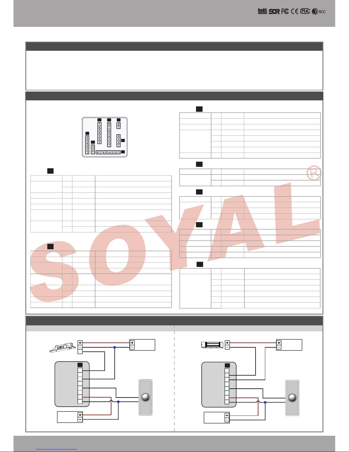
Parts Description
V130116
P1
P2P3
P6
P4
P5
P7
AR- 321H
EXIT
1
2
3
4
5
6
7
8
EXIT
1
2
3
4
5
6
7
8
E
N.C.
COM
PB
12V
GND
12V
GND
Exit Switch
12V
GND
12V
GND
12V
GND
12V
GND
12V
GND
N.O.
GND
N.O.
GND
N.O.
COM
PB
12V
GND
P1
P1
Illuminated Touch-panel
Access controller
Notice
1. Tubing: The communication wires and power line should NOT be bound in the same conduit or tubing.
2. Cable selection: Use AWG 22-24 Shielded Twist Pair to avoid star wiring. Use CAT5 for TCP/IP connection.
3. Power supply: Don’t equip reader and lock with the same power supply. The power for reader may be unstable when the lock is activating, that may make the
reader malfunction. The standard installation: Door relay and lock use the same power supply, and reader use independent power supply.
Wire Application Wire Color Description
Lock Relay
1 Blue White (N.O.)DC24V1Amp
2
Purple White
(N.C.)DC24V1Amp
Common-COM-Point
3 White (COM)DC24V1Amp
Door Contact 4 Orange Negative Trigger Input
Exit Switch 5 Purple Negative Trigger Input
Alarm Relay 6 Gray
Transistor Output Max. 12V/100mA
(Open Collector Active Low)
Power
7 Thick Red DC 12V
8 Thick Black DC 0V
P1Cable:
Wire Application Wire Color Description
Anti-Tamper
Switch
1 Red N.C.
2 Orange COM
3 Yellow N.O.
P5Cable:
Wire Application Wire Color Description
Power 1 Red DC 12V
Output
Security trigger signal
2 Purple Security trigger signal Output
Arming 3 Red White Arming Output
Duress 4 Yellow White Duress Output
P6Cable:
Wire Application Wire Color Description
1 --- ---
2 --- ---
TCP/IP Output
3
Orange White
Net - TX+
4 Orange
Net - TX-
5 Green White
Net - RX+
6 Green
Net - RX-
7 --- ---
P3Cable:
Wire Application Wire Color Description
RS-485 for Lift
Controller
1 Thick Green RS-485(B-)
2 Thick Blue RS-485(A+)
P4Cable:
Wire Application Wire Color Description
Beeper 1 Pink Beeper Output
5V/100mA, Low
LED
2 Yellow Red LED Output
5V/20mA, Max
3 Brown Green LED Output
5V/20mA, Max
Door Output 4 Blue White
Transistor Output Max. 12V/100mA
(Open Collector Active Low)
Wiegand
5 Thin Green Wiegand DAT: 0 Input
6 Thin Blue Wiegand DAT: 1 Input
WG Door
Contact
7 Orange Negative Trigger Input
WG Exit Switch 8 Purple Negative Trigger Input
P2Cable:
Connector Table
Connect to Electric Bolt Connect to Magnet Lock
Wiring Diagram
Electric Bolt
Controller
Controller
RTE RTE
POWER
12VD C
POWER
12VD C
POWER
12VD C
POWER
12VD C
Magnet Lock
Wire Application Wire Color Description
TTL Port 1 Black DC 0V
2 Yellow
TX
3 White
TE
4 Orange
RX
5 Red DC 5V
6 --- ---
Cable: P7
Optional:(Request to purchase AR-725L485 additionally)
SOYAL
ACCESS CONTROL SYSTEM
®
AR-725 (E-V2)
V130116
EXIT
1
2
3
4
5
6
7
8
1
2
3
4
5
6
7
8
N.C.
N.O.
COM
CTL
12V
Door Contact
ALM
12V
GND
12V
GND
12V
GND
12V
GND
12V
GND
12V
GND
12V
GND
N.O.
GND
N.C.
N.O.
COM
PB
12V
GND
P1
P1
N.C.
N.O.
COM
CTL
12V
E
E
BZ
RLED
GLED
WG 0
WG 1
12V
GND
1
1
1
2
2
2
3
3
3
4
4
4
5
5
5
6
6
6
7
7
7
8
8
8
1
2
3
4
5
6
12V
GND
Exit Switch
12V
GND
12V
GND
12V
GND
12V
GND
12V
GND
PB
PB
COM
COM
N.O.
N.O.
P2
P1
P1
P1
BZ
RLED
GLED
Door Output
WG 0
WG 1
WG-DS
WG-PB
7
8
EXIT
1
2
3
4
5
6
7
8
1 2 3
N.C.
N.O.
COM
CTL
12V
GND
PB
12V
GND
12V
GND
N.O.
12V
GND
12V
GND
DDR
P1
P6
AR-721RB
4
12V
N.C.
EXIT
RTE
EXIT
1
2
3
4
5
6
7
8
12V
GND
12V
GND
PB
COM
N.C.
P1
EXIT EXIT
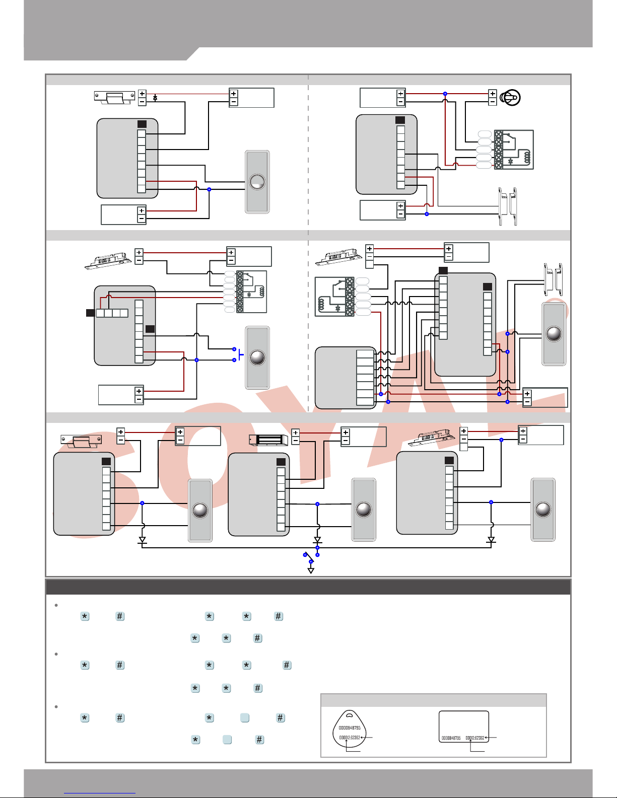
Adding and Deleting Tag
Delete a Single Tag
Input 123456 (or Master Code)
→
10 SSSSS EEEEE
[e.g.] Delete User Address: 00058
Access programming mode
→
10 00058 00058
9
9
Add Single Tag or Random tags
Input 123456 (or Master Code)
→
19 UUUUU 00001
→
Present the tag(s) with Controller
(single ta g or rando m number ed card s one by one)
→
Done
[e.g.] 2 readom cards with user addresses No. 100 and No. 101:
Access programming mode
→
19 00100 00001
→
Present the tags one by one
→
Done
Input 123456 (or Master Code)
→
19 UUUUU QQQQQ
→
Present the tags
(Presen t the tag w ith the lowest number r st .)
→
OK
Add the Sequential tags
[e.g.] User Address NO.101 to NO.120 have 20 pcs of sequential tags:(62312~62332)
:
Access programming mode
→
19 00101 00120
→
Close Tag into RF Area
(only use th e tag NO. 62312)
→
OK
Tag Information
SITE CODE
CARD CODE
SITE CODE
CARD CODE
Controller
Controller
Controller
Reader
Controller
RTE
RTE
RTERTE
RTE
POWER
12VD C
POWER
12VD C
POWER
12VD C
POWER
12VD C
POWER
12VD C
POWER
12VD C
POWER
12VD C
POWER
12VD C
POWER
12VD C
POWER
12VD C
POWER
12VD C
Connect to Electric Strike Connect to Door Contact
Electric Strike
Electric Strike
Alarm
Relay Outpot Module
Door Contact
Door Contact
Strengthen security with AR-721RB
If any re emergency, the people can escape by press a switch to open all doors
Electric Bolt
Electric Bolt
Electric Bolt
Fire Emergency
Transistor
IN4007
Transistor
IN4007
Connect to Reader
Magnet Lock
 Loading...