

Page 1
SOYAL
ACCESS CONTROL SYSTEM
®
AR-723H
V110713
P3
AR-WG-KEYBOARD AR-721-RBAR-821-RB
LED
BZ
123456
P1
P2
P3
P3
LED
BZ
12345678
AR- 821RB
AR-723H
AR-723H
N.C.
LED
BZ
N.C.
N.O.
COM
CTL
12V
1
2
3
4
5
6
7
8
1
3
5
2
4
6
GND
ALM
PB
SEN
A+
B-
12V
Door
P2P1
GND
12V
WG 0
WG 1
7
6
5
4
3
2
1
P3
P3
GND
WG0
WG1
12V
AR- 821RB
AR-723H
N.O.
GND
ALM
PB
SEN
A+
B-
12V
Door
P2P1
N.C.
N.O.
COM
CTL
12V
1
2
3
4
5
6
7
8
1
3
5
2
4
6
EXIT
DECODER
N.C.
N.O.
COM
CTL
12V
GND
PB
1
2
3
4
5
6
7
8
1
3
5
2
4
6
EXIT
AR-721RB
AR-723H
N.O.
N.C.
GND
ALM
PB
SEN
A+
B-
12V
Door
P2P1
(RS-485)
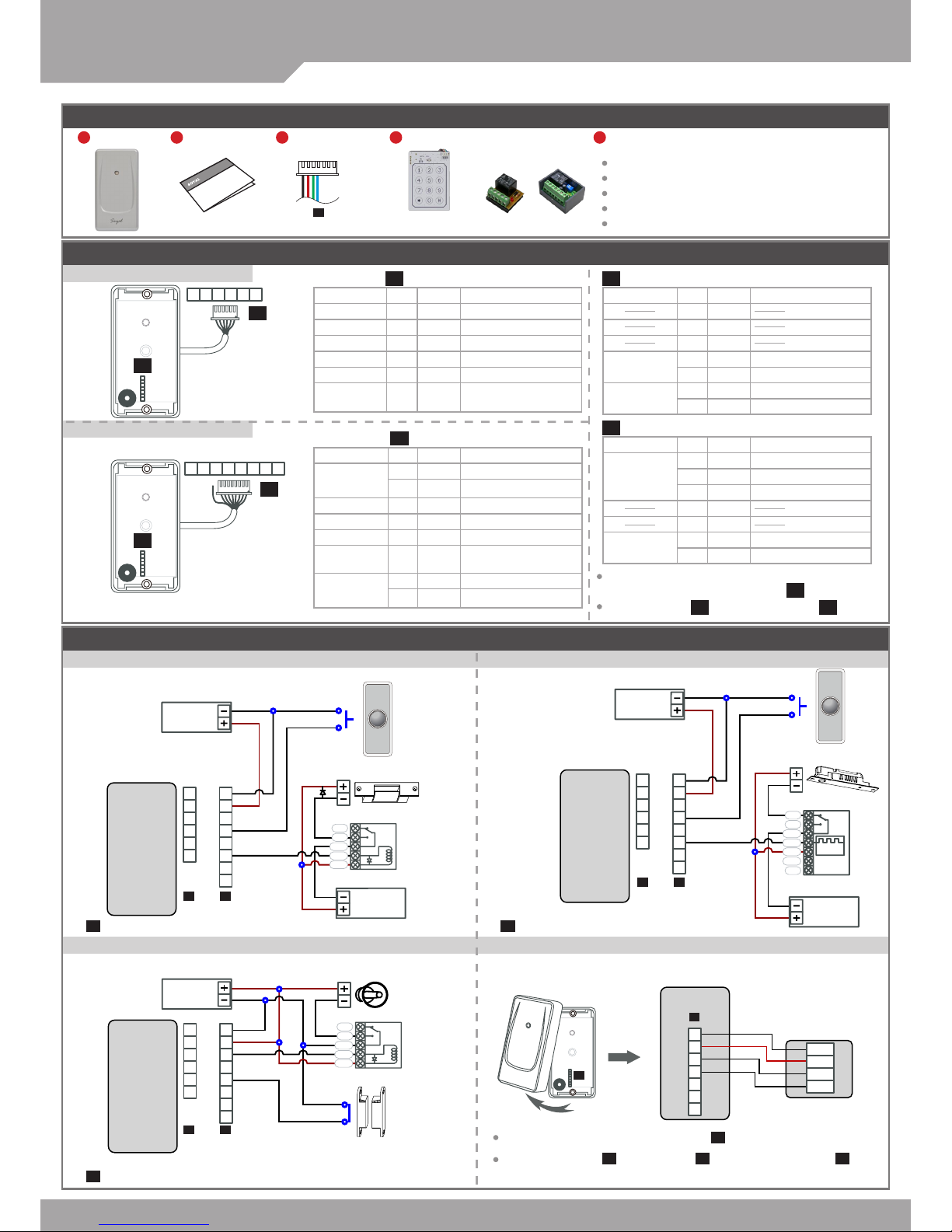
Diagram
Electric Strike
Electric Bolt
Request To Exit
Request To Exit
Blue
Red
Green
Black
WG Keyboard
WG Reader
or
Alarm
Door Contact
or
POWER
12VD C
POWER
12VD C
POWER
12VD C
POWER
12VD C
POWER
12VD C
Stand-Alone
Networking
Connect to Electric Strike Strengthen security with AR-721RB
Connect to Reader or KeyboardConnect to Door Contact and Alarm
Connector Table
(NO RS-485)
(Optional)
P4
TTL Cable
P3
WG Input Port
P1
Standalone: 6 PIN
P2
Networking: 8 PIN + GND
When update rmware or set function for
standalone model, please order .
Please unplug cable before using cable.
P3
P4
P4
Content & Feature
1
Product
2
User Guide
5
Feature
4
Optional
3
Terminal Cables
Standalone and Networking model for selection
1 Bi-color LED & 1 Buzzer
Built-in Watch Dog to prevent system from hanging
The Master Card function for adding/ deleting cards
Can set parameters by external keyboard
Application Wire Color Description
Power 1 Black DC 0V (GND)
R.T.E 2 Brown Negative Trigger Input
Power 3 Red DC 12V
Door Contact 4
Orange
Negative Trigger Input
Alarm Relay 5 Yellow Open collector output
Lock Relay 6 Green
Open collector output/
Security Trigger Signal
Application Wire Color Description
Power
1 Black DC 0V (GND)
2 Red DC 12V
Alarm Relay 3 Gray Open collector output
R.T.E 4 Purple Negative Trigger Input
Door Contact 5
Orange
Negative Trigger Input
Lock Relay 6 White
Open collector output/
Security Trigger Signal
RS-485
7 Blue RS-485 A+
8 Green RS-485 B-
Application Wire Color Description
1
2
3
WG
4 Blue WG DATA 1
5 Green WG DATA 0
Power
6 Red DC 12V
7 Black DC 0V (GND)
Application Wire Color Description
TTL
1 Yellow TX
2 White TE
3
Orange
RX
4
5
Power
6 Red DC 12V
7 Black DC 0V (GND)
or
or
or
P4
Please unload the cover before plug in cable.
If you need to use cable, unplug cable and then plug in cable.
P3
P4 P3
Diode
※
are not in order, please refer to [Connector Table]
P1
※
are not in order, please refer to [Connector Table]
P1
※
are not in order, please refer to [Connector Table]
P1
Page 2
V110713
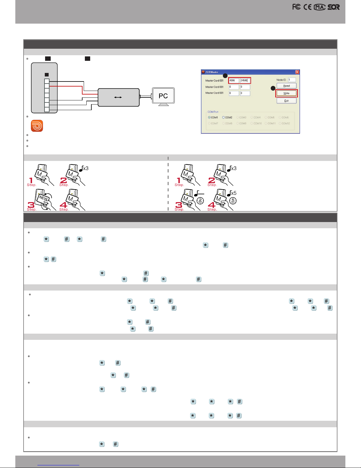
323DMaster
TTL USB
7
6
5
4
3
2
1
P3
GND
12V
RX
TE
TX
2
1
Access Controller
About Master Card
Enter the program mode
Input 123456 or PPPPPP
[e.g.] The Default Value= 123456, if already changed the Master Code= 876112, input
87 6112
→
program mode accessed
Exit the program mode
Input
Operation process
M4/M8: Individual pass code
Card or PIN: Access programming mode
→
12 UUUUU PPPP [e.g. User address: 00001 and pass code: 1234, input 12 00001 1234 ]
Card and PIN: Access programming mode
→
13 UUUUU PPPP [e.g. User address: 00001 and pass code: 1234, input 13 00001 1234 ]
M6: Public pass word
Card or PIN: Access programming mode
→
15 PPPP [Input 4- digit pass code, default value: 4321]
Card and PIN: Access programming mode
→
17 PPPP [Input 4-digit pass code, default value: 1234; PPPP=0 000: change into Card Only]
Enable controller
Access programming mode
→
20 DDD [128= Anti-pass-back(0=Disable; 1=Enable)/ 064=Access/Exit(0=Exit; 1=Access).]
Access programming mode
→
20 128 (Please refer to function default value for details.)
[e.g.] Enable Anti-pass-back, and set to Exit door= (128 x 1) + (064 x 0) = 128
Usually, anti-pass-back is commonly applied to parking areas in order to prevent from multi-entry with one card at a time, or to situations need
access and exit monitor.
C. Anti-pass-back(M4/M8)
B. Set up the password
[Only for connect to external K-series reader]
Master Code modication
Access programming mode
→
09 PPPPPPRRRRRR [Input the 6-digit new master code twice.]
[e.g.] Set the Master code to be 876112, input
123456
→
09 876112876112
A. Enter/ Exit Program Mode
Adding Tag
Present Master Card
Deleting All Tags
Present Master Card
P.S. Once MASTER CARD is presented after one
warning beep, all card data will be cleared.
After 3 short beeps
[Access programming mode]
After 3 short beeps
[Access programming mode]
Present one new card at a time
1 long warning beep after 2sec.
Present Master Card
[Exit programming mode]
5 short beeps after 5sec: cards cleared
1. 1.
2.
2.
3.
3.
4.
4.
MASTER CARD Setting for Stand-Alone
Use the MASTER CARD software
Input the MASTER CARD number, and press [Write].
Cut off and then transmit the power, the master card number will be activated.
Present the card, and the reader will ash green light 3 times and sound 3 beeps. Then the card becomes MASTER CARD and accesses programming
mode.If MASTER CARD is presented again, it will exit programming mode.
Black
Orange
White
Yellow
Converter
Red
[e.g.] No. 154 enable the anti-pass-back, and induction into the door has not been induced to leave. When he represent into the door will become
invalid , then he needs to set the reset. Access programming mode
→
26 00154 00154 2
→
Reset
[e.g.] User address from 00152 to 00684 enable the anti-pass-back function: 26 00152 00684 0
Enable card
Access programming mode
→
26 SSSSS EEEEE N
[SSSSS= User address start; EEEEE= User address end; N=0(control)/ 1(Not control)/ 2(reset)]
D. Lift control
Enable
Access programming mode
→
24 002 [002= enable lift control]
Connect with AR- 401RO16B to control oors which the user will be able to access.
Plug in cable instead of cable, the wire connection is as below gure. After connection, then have power transmission to controller.P4 P3
Page 3

SOYAL
ACCESS CONTROL SYSTEM
®
AR-723H
V110713
Enable: Access programming mode
→
Disable: Access programming mode
→
Factory Reset by its commands
When the device is stand-alone (not networking)
Access programming mode
→ 20
016
→ 24
064
→ 26
00000
01023
1 → 28
000
→ 29
29
※
Note: After the Master Code is changed, factory reset doesn’t restore the Master Code back to 123456.
Enable/Disable Arming status (for M4/M8; Factor y default armingcode is: 1234) :
Standby Mode
Enter Program Mode
After door open
The normal procedure to open door
→
Input 4 digit arming code
→
Do not open the door
→
Input 4 digit arming code
→
Present valid card
※
[The normal procedure to open door] can refer to [Access Mode].
[e.g.] User address NO. 168, only to the 6th and the 20th oor:
Access programming mode
→
21 00168 0 00100000
→
21 00168 2 000 01000
Multi oors
Access programming mode
→
21 UUUUU S FFFFFFFF
[UUUUU=User address S: 4 sets of lift control (Input: 0~3) FFFFFFFF: 8 oors setting (F=0=Disable, F=1=Enable)
Single oor
[e.g.] User address NO. 45, allow to access the 24th oor: 27 00045 24
Access programming mode
→
27 UUUUU FF
UUUU=User Address FF=Floor number (01~32 oor)
Set
Floor/ Stop
F
8
16
24
32
0
1
2
3
F
6
14
22
30
F
7
15
23
31
F
5
13
21
29
F
4
12
20
28
F
3
11
19
27
F
2
10
18
26
F
1
9
17
25
E. Setting Up the Arming
[Only for connect to external K-series reader]
Alarm conditions:
1. Arming is enabled
2.Alarm system connected
Application:
1. Door open too long: Door is open longer than door relay time plus door close time.
2. Force open (Opened without a valid user card): Access by force or illegal procedure.
3. Door position abnormal: Arming is enabled and the power is suddenly off then on.
Function Default Value
Mode4 / Mode6 / Mode8
※
Mode 6, the number of users up to 65535, since it reads CARD CODE(5 digits) only, unlike that Mode4/Mode8 read SITE CODE and CARD CODE(10 digits).
If Access Mode setting to use the PIN, it need to external the K-series Readers.
Selection= 0(none value)/ 1(1 x each value)
[e.g.] DDD value of Enable “Auto Open” + ”Exit by Push Button +
”Anti-pass-back”
=(0x1)+(0x2)+(1X4)+(1x16)+(0x32)+(0x64)+(1x128)=148;
As a result of that, the command will be 20 148 .
20 DDD
※
Default Value
Function Selection Value Application
Attendance
※
0: Yes 1: No 001 Networking
Auto Re-lock
※
0: Disable 1: Enable 002 Networking/Stand-Alone
Auto Open
※
0: Disable 1: Enable 004 Networking/Stand-Alone
Door open button input
0: Disable※1: Enable 016 Networking/Stand-Alone
Master Controller of Network
※
0: Slave 1: Mater 032 Networking
Access/Exit
※
0: Exit 1: Access 064 Networking
Anti-pass-back
※
0: Disable 1: Enable 128 Networking
24 DDD
※
Default Value
Function Selection Value Application
Auto-open door without cards at auto open zone
※
0: Disable 1: Enable 001 Networking/Stand-Alone
Alarm Output/ Lift Control
※
0: Alarm Output
1: Lift Control
002 Networking/Stand-Alone
Stop Alarm by door close or by push button
0: None
※
1: Yes 064 Networking/Stand-Alone
28 DDD
※
Default Value
Function Selection Value Application
Dual Door Control
※
0: Disable 1: Enable 064 Networking/Stand-Alone
Force Open Alarm Output※0: Disable 1: Enable 128 Networking/Stand-Alone
Mode
Networking/
Stand-Alone
User
Capacity
Access Mode
Auto- show
Duty time
Event log
Capacity
120
Holidays
Anti
force
Time
Zone
Lift
Control
Anti-pass-
back
M4
Networking/
Stand-Alone
1,024
1.Card only
2.Card and PIN
(4-di git PIN)
+
3.Card or User address
(5-digit)
+ Individual PIN
(4-digit
indivi dual PIN)
+
Yes 1,2 00 Yes Yes No 32 Yes
M6 Stand-Alone 65,535
1.Card only
2.Card and PIN
(4- digit public PI N= Arming PWD)
+
3.Card or PIN
(4-di git public PIN= D uress code)
No No No No No No No
M8
Networking/
Stand-Alone
1,024
1.Card only
2.Card and PIN
(4-digit individual PIN)
+
3.Card or PIN
(4-digit individual PIN)
Yes 1,2 00 Yes Yes No 32 Yes
Page 4

V110713
Access Controller
Command List
Function Command Description Mode
Enter ing progr amming mo de
PPPPPP
PPPPPP= Master Cod e, default valu e=123456
M4/M6/M8
Exit ing progr amming mo de
M4/M6/M8
Exit ing program ming mode and e nabling ar ming status
M4/M8
Node ID s etting (C onnectin g to 716E
00 NNN
NNN= Node ID, range: 0 01~254
M4/M8
Node ID sett ing ( Conne cting to PC d irec tly with out
via 716E)
00 NNN VVV nnn
NNN= Node ID of Ac cess Contr oller, VV V=Virtua l 716E Node ID,
nnn=D oor number; r ange:001~25 4
M4/M8
Mifar e tag / card f ormat (Opt ional)
01 N
N: 0=IS O14443A; 1=ISO144 43B; 2=ISO15 693;
3=I Co de1; 4=I Code2
PS.1. Please sele ct the comp liance,r st.
2. Make sur e reader and ca rd using the s ame compli ance.
M4/M8
Door re lay time se tting
02 TTT
TTT=Do or relay time 000 = Output con stantly
001~6 00=1~6 00 sec.
601~6 09=0.1~0. 9 sec.
M4/M6/M8
Alar m relay tim e setting
03 TTT
TTT=Ala rm relay time 000 = Output con stantly 001~ 600=1~60 0 sec.
M4/M6/M8
Contr ol mode set ting
04 N
N=Mode 4=Mode4; 6=Mo de6; 8=M ode8
M4/M6/M8
Armin g delay tim e settin g
05 TTT
TTT=Ala rm relay time 001~6 00=1~6 00 sec.
M4/M6/M8
Alar m delay tim e settin g
06 TTT
TTT=Ala rm delay time 001~6 00=1~6 00 sec.
M4/M6/M8
Maste r card set ting
07 SSSSS EEEEE
SSSSS -EEEEE= 0000 0-01023 (0 0000 -03000 fo r AR-725H);
SSSSS =Start ing user addr ess; EEEEE=En ding user addr ess
M4/M8
Auto- open time zon e settin g
08 N HHMMhhmm 7123456H
N= 0(1st time zo ne) / 1(2nd time zone)
HHMM = Starti ng time; hhmm= e nding time
(i.e.: 083 01200=0 8:30 to 12:00)
7123456H = 7 days of week (Sun /Mon/ Tue/Wed/ Thu/Fri/ Sat)+ Holiday
(H= 0: dis able; 1: enable); Holi days establ ish by the soft ware.
M4/M6/M8
Maste r code set ting
09 PPPPPPRRRRRR
PPPPPP= New master c ode
RRRRR R=Repeat t he new master c ode
M4/M6/M8
Setting
Suspe nd tag(M6 )
10 SSSSS EEEEE
=Suspe nd =Delete;
SSSSS =Start ing user addr ess, EEEEE=En ding user add ress
M4/M6/M8
Delet e tag(M4)
10 SSSSS EEEEE M6
Set a seq uence of ca rds as "rea d and acce ss"
11 SSSSS EEEEE
SSSSS =Start ing card num ber; EEEEE=En ding card num ber
M4/M8
Activ e the suspe nded card s
11 SSSSS EEEEE
SSSSS =Start ing user addr ess; EEEEE=En ding user add ress
M4/M8
Set t he car ds as Card m ode OR PIN mo de by user
address
12 UUUUU PPPP
Acces s mode: Card or PIN ; UUUUU=user a ddress;
PPPP=4 -digit p ass code 00 01~999 9
M4/M8
Se t the ca rd s as Car d A ND PIN mo de by use r
address
13 UUUUU PPPP
Acces s mode: Card and PI N; UUUUU=use r address;
PPPP=4 -digit p ass code 00 01~999 9
M4/M6/M8
M4: Dure ss code se tting
M6: Publ ic PIN sett ing (Card or PI N)
15 PPPP
PPPP=4 -digit pass co de (default valu e=4321)
P.S. Duress cod e will be unavaila ble and becom e a public PIN at ac cess mode “C ard or PIN” of M6
M4/M8
Card num ber modi catio n
16 UUUUU SSSSSCCCCC
UUUUU = User addre ss; SSSSS= 5-dig it site code;
CCCCC =5-di git card cod e
M4/M6/M8
M4: Arm ing pass co de setti ng
M6: Publ ic PIN sett ing (Card and PI N)
17 PPPP
PPPP=4 -digit pass c ode ( default value =1234; disa ble Arming PWD =0000)
P.S. Arming PWD c ode will be unav ailable and be come a public PI N at access mo de “Card PIN ” and of M6
M4/M6/M8
Door op en waitin g time
18 TTT
TTT=Do or open wait ing time: 001~ 600=1~ 600 sec.; d efault value: 15 se c.
M4/M8
Set the c ard by indu ction
19 UUUUU QQQQQ
UUUUU =User add ress;
QQQQQ =Card qua ntity(00001=Cont inuously in ducting)
M4/M6/M8
Reade r additi onal sett ing
20 DDD
Please re fer to functi on default val ue for detail s.
M4/M6/M8
Lift c ontrol se tting: mul ti-d oors
21 UUUUU S FFFFFFFF
UUUUU =User addres s, S=4 sets of lif t control(0 ~3); FFFFFFFF=8 assi gned oor
(F=0: Di sable, 1: Enable)
M4/M8
Add/D elete ta g by induct ion (M6 only)
22 N
N=0( Delete tag); N=1(Ad d tag)
M6
AR-4 01ROsite nu mber dip sw itch
23 NNN TTT
NNN=s ite number, TT T= relay time: 00 0~60 0=1~60 0 sec.
M4/M8
Contr oller par ameter se tting
24 DDD
Please re fer to functi on default val ue for detail s.
M4/M6/M8
Contr oller tim e clock set ting
25 YYMMDDHHmmss
YYM MDDHHm mss: Year/ Month/ D ay/ Hour/ Min./ S ec.
M4/M6/M8
Anti-pass-back (Enab le user)
26 SSSSS EEEEE N
SSSSS =Start ing user addr ess; EEEEE=En ding user addr ess;
N=0/ Enable; N=1/D isable; N=2 /Initia l
M4/M8
Singl e oor sett ing
27 UUUUU FF
UUUUU =User Add ress; FF=Flo or (01~32 oor)
M4/M8
Dual do or control / Active or in active ar ming for for ce open
28 DDD
Please re fer to functi on default val ue for detail s.
M4/M6/M8
Delet e all tags
29 29 M4/M6/M8
Enabl e the secur ity tri gger sign al ( with AR-7 21RB)
34 064
(Enab le)
34 000
(Disable)
To Cha nge the "Do or Lock " bec ome the sec uri ty trig ger sig nal, w hen
contro ller is conn ected with A R-721RB.
M4/M6/M8
9
9
 Loading...