

Page 1
SOYAL
23
Access Control System
Soyal AR721U661U721K hardware operation guide
Revision: V1
Date released: 1 Nov 2006
UM_Soyal721KP721U661UV1
Table of Contents
1. Main Feature ------------------------------------------ 2
2. AR-721U Installation ------------------------------------------3
2.1 Steps
2.2 Installation Notice
2.3 Terminal Cable ------------------------------------------4
2.4 PCB board ------------------------------------------5
2.4.1 No waterproof
2.4.2 Waterproof
2.5 Installation diagram -------------------------------------------6
2.5.1 AR-721U & AR-721H
2.5.2 AR-721U & AR-727H -----------------------------------------7
2.5.3 AR-721U & AR-821EF ---------------------------------------- 8
2.5.4 AR-721U & AR-829E -----------------------------------------9
3. AR-721K Installation ---------------------------------------10
3.1 Steps
3.2 Installation Notice
3.3 Terminal Cable ------------------------------------------11
3.4 PCB board
3.5 Installation diagram ----------------------------------------12
3.5.1 AR-721K & AR-721H
3.5.2 AR-721K & AR-727H -----------------------------------------13
3.5.3 AR-721K & AR-821EF ----------------------------------------14
3.5.4 AR-721K & AR-829E ---------------------------------------- 15
4. AR-661U Installation --------------------------------------- 16
4.1 Installation Notice
4.2 Terminal Cable
4.3 Installation diagram ----------------------------------------17
4.3.1 AR-661U & AR-721H
4.3.2 AR-661U & AR-727H ----------------------------------------18
4.3.3 AR-661U & AR-821EF ----------------------------------------19
4.3.4 AR-661U & AR-829E -----------------------------------------20
4.4 The standalone controller do anti-pass-back with 2 pcs of AR-661U ---------21
4.5 Testing table of AR-661U Reading Range depends on tags -------5 Troubleshooting ----------------------------------------24
6 Return of Products / Warranty
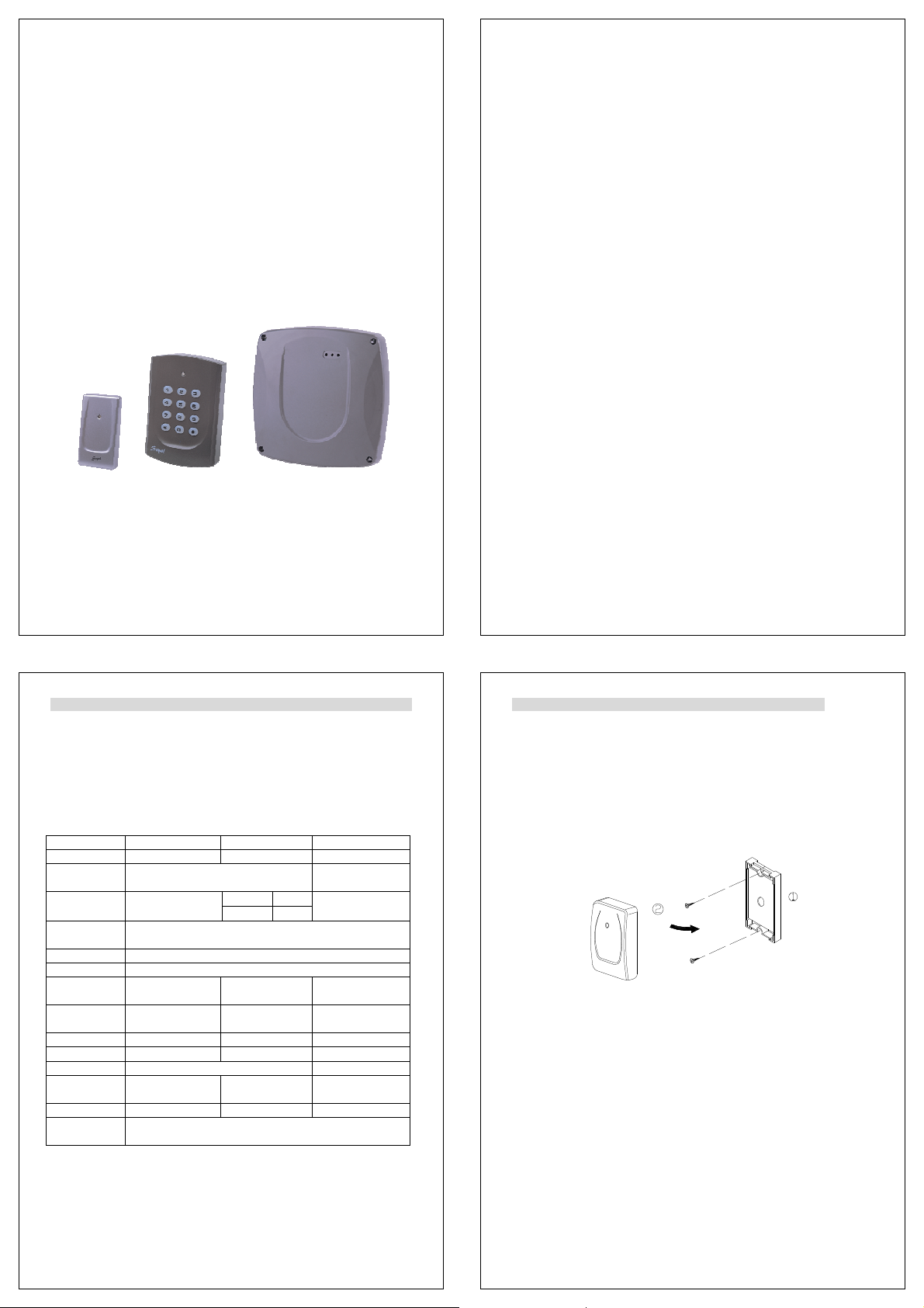
1. Main Features
Easily integrated with soyal or other access control systems.
Programmable various outputs formats Wiegand , magstripe or serial.
Built-in watchdog to prevent the system from halting
A bi-color LED indicator and a beep sound.
Item AR-721U AR-721K AR-661U
RF Frequency 125KHz 125KHz / 13.56MHz
Power
Requirement
Consumption
Communication
Interface
Baud Rate 9600 bps (N, 8, 1)
Environment -20°C to +75°C
Proximity
Reading Range
Indicator A bi-color LED and a
Keypad - Yes Waterproof Option - Yes
Color Dark Pearl Gray / Silver Dark Pearl Gray
Dimensions
(mm)
Weight (g) 40±5 90±10 1,000±50
Housing
Material
beeper
81(H)*43(W)*18(D) 111(H)*77(W)*26(D) 228(H)*228(W)*38(D)
9-16VDC 12-18VDC
50mA
3-8cm 10-18cm (125K) /
125KHz 80mA Power
13.56MHz 0.72W
WG 26 / 34, ABA-II, ASYNC, OMRON
3-8cm (13.56M)
A bi-color LED and
a beeper
ABS
125KHz
350 mA
33-60cm
Three LED and a
beeper
1
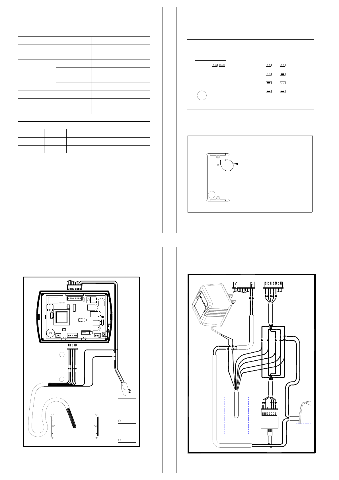
2. AR-721U Installation
2.1 Steps
1. Use the screwdriver to screw the mounting plate on the wall.
2. Pull cable ends through the access hole in the mounting plate. AR-721U must be
connected before power is applied to the single door controller.
3. Attach the AR-721U to the mounting plate.
4. Apply power. The red LED will flash once and the beeper will sound.
2.2 Installation Notice
1. AR-721U is narrow enough to mount to most mullions and door frames.
2. Single door controller locate inside the secure area for use as an exit controller, the
auxiliary reader locate exterior wall for use as an entrance reader, but not directly
behind single door controller. For best reading distance, offset the single door
controller and auxiliary reader by about 50 cm above and 12 m below (suggestion
value).
3. Normally, AR-721U will read a Card / Key Tag at up to 8 cm. However, when
AR-721U reader is mounted directly on a metal surface, the reading distance
decreases slightly. To reduce this effect, install wood or plastic between the
mounting surface and mounting plate, this will restore most of the reading distance.
2
3
Page 2
2.3 Terminal Cable
Table 1 - Color Coding
Wire Application Wire Color Description
1 Red DC Power 12V Power
Beeper 7 Purple Beeper Input ( Low Sound )
8 White Card Present
Beeper 9 Gray Beeper Output
Output
WG26
34/26 Open Close Open Close
ABA Open Open Close Close
AR-721U RS-232 Format: ( 9600,N, 8, 1 SOYAL Format )
DAT:0: TTL Inverted Serial Output.
( Can connect to PC comm port )
DAT:1: TTL Serial Output.
( connect to PC comm. port through RS-232 invert driver )
2 Black DC Power 0V
3 Yellow LED Red Input ( Low Bright) LED
4 Brown LED Green Input ( Low Bright)
5 Blue Wiegand DAT:1 Wiegand
6 Green Wiegand DAT:0
Output Selection
WG34
RS-232 Magnetic ( ABA )
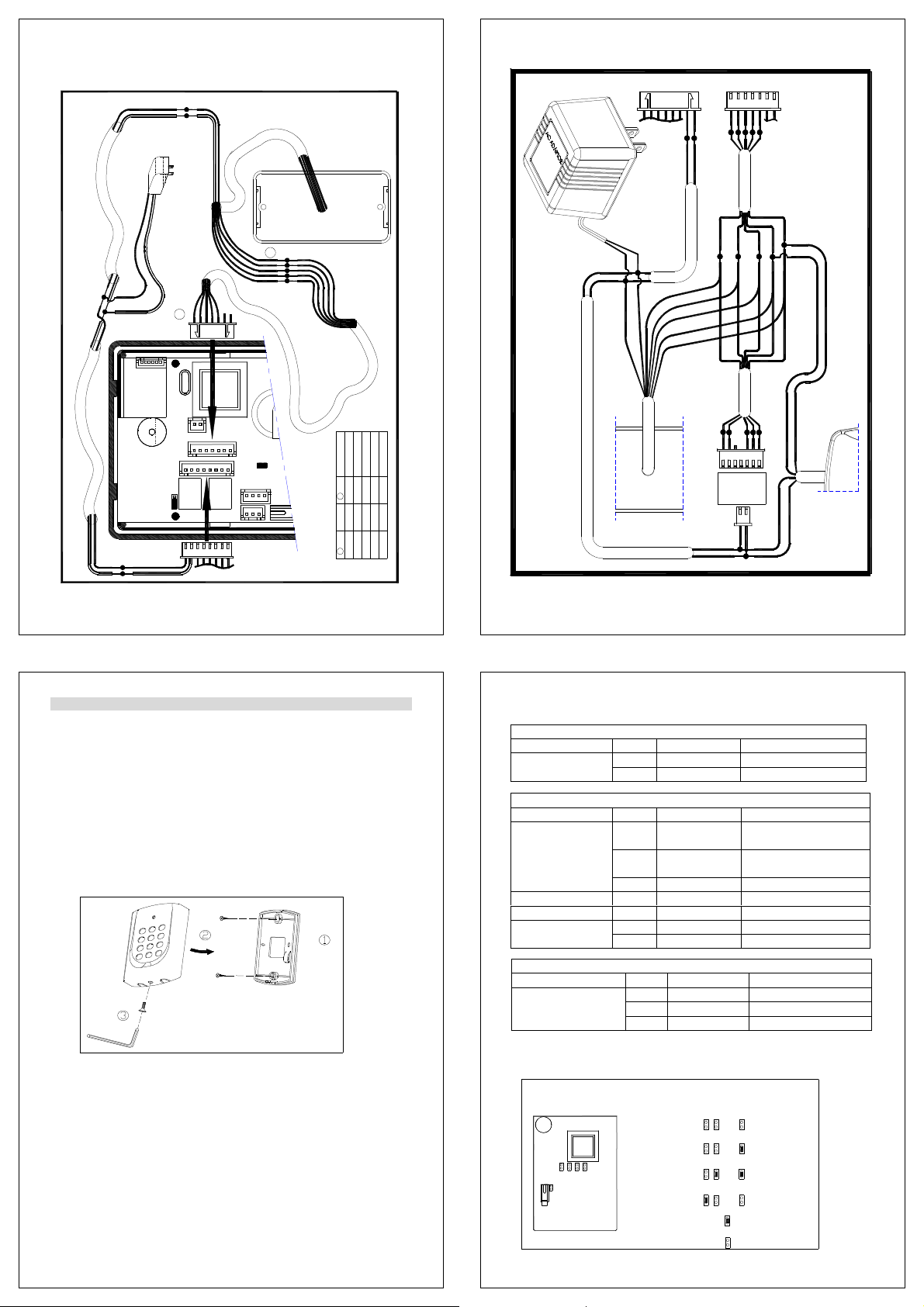
2.4 PCB board
2.4.1 No waterproof
Output Format
2.4.2 Waterproof
Output Format
ABA 34126
721U PCB
Buzzer
Buzzer
AR-721U
WG 26
WG 34
RS-232
ABA
II
ABA 34126
34126ABA
34126ABA
34126ABA
Connect for WG34 bit (Default)
Cut for WG26 bit
(Default)
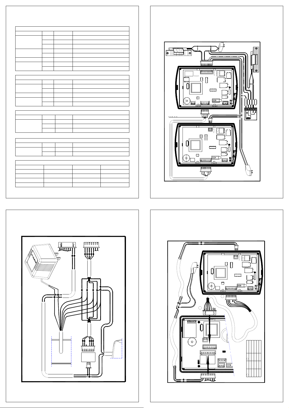
2.5 Installation diagram
2.5.1 AR-721U & AR-721H
The installation of 721H and auxiliary reader 721U
RELAY
721H5DS
CN4
4
5
2.5.2 AR-721U & AR-727H
CN1
P1
CN1
7AC2
CN2
CN2
1
P2
SOYAL
CN3
Red
Black
12VDC 2A
Power Supply
1
Red
Black
A
+ 12VDC
Red
B
-GND
Black
Power Supply
12VDC 500mA
DAT:0
DAT:11
Function
Red LED
Green LED
Beeper input
Pin
B
Purple
Green
Brown
Yellow
Pink
Blue Blue
Color
Green
Brown
AR-721U
Yellow
5
324
Pin
A
The installation of 727H and auxiliary readers
721U
727H
CN3
Black(-GND)
Red(+ 12VDC)
Yellow
Brown
w
o
l
l
e
Y
n
w
o
r
B
e
l
p
r
u
P
n
e
e
r
G
e
u
l
B
Brown
Yellow
CN1
Blue
Green
Pink
Pink
Green
Blue
~
1
CN2
721K
CN1
Black
Red
661U
6
7
Page 3
2.5.3 AR-721U & AR-821EF
reader 721U
Black(-GND)
The installation of 821EF and auxiliary
Black(-GND)
Red(+ 12VDC)
2.5.4 AR-721U & AR-829E
829E
Black(-GND)
Red(+ 12VDC)
12VDC 2A
Power Supply
Red(+ 12VDC)
A
CN2
P2
B
12VDC 2A
Power Supply
~
1
821EF
+ 3V
TP1
CN1
P1
CN2
DAT:1
DAT:0
Function
Red LED
Green LED
CN1
CN7
CN3
Beeper Input
Pin
B
Purple
Green
Brown
Yellow
Blue Blue
Pink
Color
Green
Brown
Yellow
3
546
7
Pin
A
The installation of 829E and auxiliary readers
1
Red
Black
CN1
Black(-GND)
Red(+ 12VDC)
Yellow
Brown
w
o
l
l
e
Y
n
w
o
r
B
e
l
p
r
u
P
n
e
e
r
G
e
u
l
B
Brown
Yellow
CN2
Blue
Green
Pink
Pink
Green
Blue
~
1
CN2
721U
721K
CN1
Black
Red
661U
8
3. AR-721K Installation
3.1 Steps
1. Use the screwdriver to screw the mounting plate on the wall.
2. Pull cable ends through the access hole in the mounting plate.
3. Connect plug P1 to socket CN1 on the AR-721K circuit board.
4. Attach the AR-721K to the mounting plate and install screw
(supplied) into the hole at the bottom with the Allen wrench (supplied).
5. Apply power. The red LED will flash once and the beeper will sound. Refer to
AR-721K must be connected before power is applied to the single door controller.
Connect plug P2 to socket CN2 on the AR-721K circuit board.
Connect plug P3 to socket CN3 on the AR-721K circuit board.
beginning of this manual for programming.
3.2 Installation Notice
1. Single door controller locate inside the secure area for use as an exit controller, the
auxiliary reader locate exterior wall for use as an entrance reader, but not directly
behind single door controller. For best reading distance, offset the single door
controller and auxiliary reader by about 50 cm above and 12 m below (suggestion
value).
2. Normally, single door controller will read a Card / Key Tag at up to 15 cm. However,
when single door controller or optional auxiliary reader is mounted directly on a metal
surface, the reading distance decreases slightly. To reduce this effect, install wood or
plastic between the mounting surface and mounting plate, this will restore most of the
reading distance.
AR-721K can cover standard electrical boxes.
9
3.3 Terminal Cable
Wire Application Wire Color Description
Wire Application Wire Color Description
Wiegand
ABA
4 No Connection
Beeper
LED
Wire Application Wire Color Description
Tamper Switch
Table 1 - Connector P1 Color Coding
1 Thick Red DC Power 12V Power
2 Thick Black DC Power 0V
Table 2 - Connector P2 Color Coding (Wiegand Read Head )
1 Thin Blue Wiegand DAT:1 Input
ABA Format:Clock
2 Thin Green Wiegand DAT:0 Input
ABA Format:Data
3 Orange ABA Format Card Present
5 Pink Beeper Input ( Low Sound )
6 Brown LED Green Input ( Low Bright)
7 Yellow LED Red Input ( Low Bright)
Table 3 - Connector P3 Color Coding (Tamper Switch )
1 Red N.C.
2 Orange COM
3 Yellow N.O.
3.4 PCB board
Output Format
Buzzer
721K
1FF9
J1 J3WG
J2
BIT(26/34)
WG 26
WG 34
WG 34
ABA 10
SOYAL Format
EM Format
WG RST
J2J2WG
J2
WG
J2
WG
J3
J3
(Default)
RST
RST
RST
(Default)
10
11
Page 4
Mifare Terminal Cable
Wire Application Wire Color Description
6 Grey NO
Wire Application Wire Color Description
Beeper 3 Pink Beeper Input (Input Low)
Wire Application Wire Color Description
Tamper Switch
Wire Application Wire Color Description
Module
Output SET1 SET2 Note
WG-26 Open Open Hex
WG-34 Open Close Hex
ABA-10 Close Open BCD 10
ABA-5-5 Close Close BCD 5:5
Table 1 - Connector P1 Color Coding
1 Blue Whithe NO Connection
2 Purple White NO Connection
3 White NO Connection
4 Orange SET2 Output Format
5 Purple SET1
7 Thick Red DC 12V Power
8 Thick Black DC 0V
Table 2 - Connector P2 Color Coding
1 Thin Blue Wiegand DAT : 1 Output Wiegand
2 Thin Green Wiegand DAT : 0 Output
4 Brown LED Green Input (Input Low) LED
5 Yellow LED Red Input (Input Low)
Table 3 - Connector P3 Color Coding
1 Red N.C.
2 Orange COM
3 Yellow N.O.
Table 4 - Connector P4 Color Coding
1 Thick Blue RS-485(B-) Networking
2 Thick Green RS-485(A+)
Table5- Output Selection
3.5 Installation diagram
3.5.1 AR-721K & AR-721H
(N.O)
Blue White
P 1
CN1
RELAY
7AC2
721H5DS
CN4CN2
Green(DAT:0)
Pink (ALM)
Brown(LED)
Yellow(LED)
Blue(DAT:1)
CN2
P 2
721K
7AC2
CN4CN2
The installation of 721H and auxiliary reader 721K
CN2
P 2
+ 12VDC
-GND
12VDC 2A
COM)
White (
CN1
CN1
Power Supply
Red
Black
Gray
-GND
+ 12VDC
-GND
SOYAL
CN3
Red
Black
P 1
CN1
SOYAL
CN3
1
+ 12VDC
N.C
N.O
ALM
COM
+ 12VDC
-GND
+ 12VDC
~
Power Supply
12VDC 500mA
3.5.2 AR-721K & AR-727H
12VDC 2A
Power Supply
The installation of 727H and auxiliary readers
Black
721U
12
13
3.5.3 AR-721K & AR-821EF
1
Red
727H
CN3
Black(-GND)
Red(+ 12VDC)
Yellow
Brown
w
o
l
l
e
Y
n
w
o
r
B
e
l
p
r
u
P
n
e
e
r
G
e
u
l
B
Brown
Yellow
CN1
Blue
Green
Pink
Pink
Green
Blue
~
1
CN2
721K
CN1
Black
Red
661U
)
D
)
N
C
G
D
(-
V
k
2
c
1
a
l
B
(+
d
e
R
12VDC 2A
reader 721K
Power Supply
CN1
P1
CN1
Black(-GND)
Red(+ 12VDC)
The installation of 821EF and auxiliary
Black(-GND)
Red(+ 12VDC)
A
CN2
P2
TP1
CN1
P1
27BF
721K
CN2 CN4
B
P2
1
CN2
~
SOYAL
CN3
~
1
821EF
+ 3V
CN2
DAT:024
DAT:1
Red LED
Function
Green LED
CN1
CN7
CN3
Beeper Input
657
Pin
1
B
Pink
Blue
Color
Green
Brown
Yellow
3
657
Pin
A
14
15
Page 5
3.5.4 AR-721K & AR-829E
12VDC 2A
Power Supply
Black
721U
The installation of 829E and auxiliary readers
3.5.5 721K
1356
& AR-721H
1
829E
CN1
CN2
Black(-GND)
Red(+ 12VDC)
Blue
Yellow
Red
w
o
l
l
e
Y
n
w
o
r
B
e
l
p
r
u
P
n
e
e
r
G
e
u
l
B
Yellow
Green
Pink
Brown
Pink
Green
Brown
Blue
1
Black
Red
~
CN2
721K
CN1
661U
16
4. AR-661U Installation
4.1 Installation Notice
Minimum distance between AR-661U & other proximity Reader ( 200cm )
2
1
3
5
4
6
8
7
9
0
#
*
R>200CM
4.2 Terminal Cable
Wire Application Wire Color Description Remark
5 White Card Present
Beeper 6 Purple Beeper Output
Output WG26 WG34 RS-232 WG34 + 4
SEL1 Open Close to GND Open Close to GND
SEL2 Open Open Close to GND Close to GND
Note:
WG34+4: Follow 0101 after WG34 data stream for reader identification.
See Also:AR-721H do anti-pass-back with 2 pcs of AR-661U.
Table - Color Coding
1 Red 12-18VDC regulated Power
2 Black Power Ground
3 Blue Wiegand DAT:1 Open collected Wiegand
4 Green Wiegand DAT:0 Open collected
7 Yellow SEL1 Output Selection
8 Brown SEL2
Output Selection
17
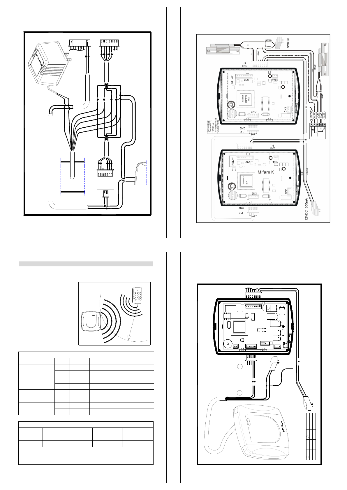
4.3 Installation diagram
4.3.1 AR-661U & AR-721H
4.2.1 AR-661U & AR-727H
The installation of 721H and auxiliary reader 661U
CN1
P1
RELAY
721H5DS
CN4
CN1
7AC2
CN2
CN2
1
P2
~
SOYAL
CN3
Red
Black
A
+ 12VDC
Red
Black
-GND
B
Power Supply
12VDC 500mA
DAT:1
Function
Pin
Blue
B
Green
Blue
Color
Green
1
2 DAT:0
Pin
A
18
19
Page 6
4.3.2 AR-661U & AR-727H
12VDC 2A
Power Supply
Black
721U
The installation of 727H and auxiliary readers
4.3.3 AR-661U & AR-821EF
1
Red
727H
CN3
Black(-GND)
Red(+ 12VDC)
Yellow
Brown
w
o
l
l
e
Y
n
w
o
r
B
e
l
p
r
u
P
n
e
e
r
G
e
u
Bl
Brown
Yellow
CN1
Blue
Green
Pink
Pink
Green
Blue
~
1
CN2
721K
CN1
Black
Red
661U
reader 661U
Black(-GND)
Red(+ 12VDC)
12VDC 2A
Power Supply
12VDC 2A
Power Supply
A
CN2
P2
The installation of 821EF and auxiliary
821EF
TP1
Black(-GND)
Red(+ 12VDC)
CN1
P1
B
~
1
+ 3V
CN2
DAT:1
CN1
CN7
CN3
Function
Blue
B
GreenGreen
Blue
Color
3
4 DAT:0
Pin Pin
A
4.3.4 AR-661U & AR-829E
1
12VDC 2A
Power Supply
Black
721U
The installation of 829E and auxiliary readers
20
21
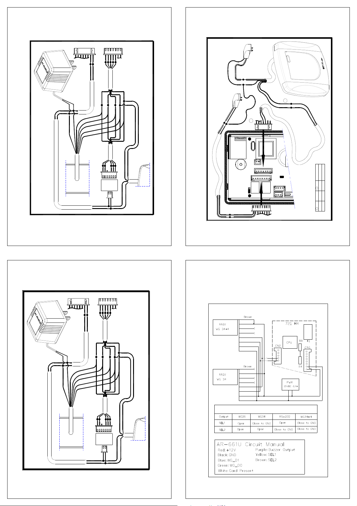
4.4 The standalone controller do anti-pass-back with 2 pcs of
AR-661U
Standalone controller includes AR-721H, AR-727H and AR-829E.
829E
CN1
Black(-GND)
Red(+12VDC)
Yellow
Brown
Red
w
o
l
l
e
Y
n
w
o
r
B
e
l
p
r
u
P
n
e
e
r
G
e
u
l
B
Brown
Yellow
CN2
Blue
Green
Pink
Pink
Green
Blue
~
1
CN2
721K
CN1
Black
Red
661U
And here is AR-721H & 2 pcs AR-661U diagram.
AR-721H do anti-pass-back with 2 pcs of AR-661U
Yellow
White
Purple
Green
Bule
Black
Red
Yellow
White
Purple
Green
Bule
Black
Red
Green
Blue
Output Selection
Red
Black
22
23
Page 7

When the distance between 2 pcs 661U is less than 6 meter (suggestion
distance
value), we can use the following ways to solve in order to avoid interference
with each other to result in reading distance decrease.
Slaver
SYNLRF
GND
Cable
Two AR-661U Reader WIRING (RF switching)
Master
Output
SYNLGND RF
SYNLGND
RF
Single Reader (RF always ON)
4.5 Testing table of AR-661U Reading Range depends on tags
Testing circumstances: Voltage 12V/500mA, No other jamming in 5 meters.
Testing
Item no. Name
AR-701KPC
Key-chain
RW-2
AR-2561
Thick Card
TRW
RW
Long
AR-2563 TRL
(Read Only)
(R/W)
(R/W)
ISO Card
Card
Sample
S/N
1 35
2 37
3 38
1 56
2 55
3 60
1 40 AR-8972 ISO
2 42
1 66
2 65
3 56
Distance
(cm)
Maximum
(cm)
Minimum
(cm)
38 35 36.5
60 55 57.5
42 40 41
66 56 61
Average
(cm)
AR-661U Partial drawing
24
5. Troubleshooting
Questions Answer
No appearance 1. Check power, if it is 9 – 18 VDC adaptor?
2. Check if the polarity is correct?
3. The unit should make a beep sound when any key on
the keypad is depressed (AR-721K).
6. Return of Products
If you think that you have a defective unit, please contact the distributor who sold you the
unit. All service and repairs must be done through an authorized distributor.
7. Warranty
SOYAL warrants that the product(s) shall be free from manufacturing defects in
materials and workmanship for a period of fifteen (15) month from the date of delivery
provided that the product was properly installed and used. The foregoing warranty shall
not apply to defects resulting from abuse, misuse, accident, unauthorized alteration or
repair, neglect, acts of God (such as floods, fire, etc.). SOYAL shall, at its option, either
repair or replace product(s) which prove to be defective within the warranty period.
SOYAL will replace any product found to be defective within the first three months of
purchase provided said product was properly installed and used. Distributor agrees to
insure the product or assume the risk of loss or damage in transit to prepay shipping
charges and to use the original shipping container or equivalent. Customers shall seek
assistance from the distributor who sold you product(s). Repaired or replaced product(s)
are warranted for ninety (90) days from the date of repair or replacement, or for the
remainder of the original product’s warranty period, whichever is longer.
Note: Don’t tear a lable such as
0506- 1 23 456
on the PCB board, because it is
AR-661UXXXX
SOYAL warranty.
25
26
 Loading...