

Page 1

AR-716EV2 (RS-485)
AR-716Ei (10 Base-T)
Multi-door Networking Controller
User’s Guide
Version: 7.2
May 6, 2004
Page 2

Table of Contents
1. Introduction --------------------------------------------------------------------------------------------- 2
2. Installation --------------------------------------------------------------------------------------------- 3
3. Software Setting --------------------------------------------------------------------------------------------- 4
3.1 701 Server software setting of external weigand reader --------------------------------- 4
3.2 Door number setting of 701E Parameter --------------------------------- 4
3.3 DI Input V.S. Relay Output Connection Setting of 701E Parameter --------------- 5
3.4 Weigand reader LED and Buzzer indicators --------------------------------- 5
4. AR-716E-IO Software Setting --------------------------------- 6
4.1 Set relay time --------------------------------- 6
4.2 AR-716E-IO hardware installation --------------------------------- 6
4.3 Push Button & Lock installation --------------------------------- 7
5. AR-727i Configuration --------------------------------- 8
5.1 Reset to Factory Default of the AR-727i --------------------------------- 8
5.2 DIP Switch Settings --------------------------------- 8
5.3 AR-727i’s contains three LED indicators, as described in the following table --- 8
5.4 How to set IP address on the AR-716Ei --------------------------------- 9
5.4.1 Get IP address by using Net727i software --------------------------------- 9
5.4.2 Get IP address by DHCP Server --------------------------------- 13
5.4.3 Get IP address by AR-801CM (COM Port) connects to PC --------------------------- 16
6. Installation diagram --------------------------------------------------------------------------------------- 19
6.1 AR-716Ei and AR-721H networking installation --------------------------------- 19
6.2 AR-716EV2 and AR-721H networking installation --------------------------------- 20
6.3 Points for attation --------------------------------------------------------------------------------- 21
1
Page 3

3. Software Setting
3.1 701 Server software setting of external weigand reader
How to enter?
Step1: Click the 701 Server Icon twice to access the Server on the down right corner of the
windows.
Step2: Click Tool Bar Icon (701E parameter) for the windows.
Step3: Enter networking controller node ID, then click “Read”.
Step4: Click the page of Door Number.
Power Must higher than 13.8VDC
Ethernet
Battery
Node: 009
To
Node: 016
Node: 001
To
Node: 008
~~
~~
AR-721H4
AR-721H4
AR-801CM
To PC
DC15V
~
~
Next
Controller
CN4
~~
1
DC12V
CN4
K1
K2
K3
K4
COM
CN2
Vin
Vin
BV+
BV-
CH2
CH1
HOST
1
K1
K2
K3
K4
COM
COM
DI.4
DI.3
DI.2
DI.1
V12
CN5
2
JP5
2-3 On:Clear
3
2
Reset to default value
1
(Must Power OFF)
JP5
3
1-2 On:RUN
2
Normal mode
1
CN1
CN3
JP4
JP1
K1
RELAY
K3
D10
AR-727i
D12
JP2
RELAYRELAY
K2
RELAY
K4
D11
D9
JP3
2
Battery
PORT1
Red / Red 12V
AR-721U
JP5
1
AR-716Ei
Blue / Blue D1
Black / Black GND
Green / Green D0
Power
Reset
Channel 2 RX
Channel 2 TX
Channel 1 RX
Channel 1 TX
Host RX
001
002
003
033
~
3
4
641
ON
12345678
216832
ON
ON
ON
ON
128
1
2
1+2
~
1+32
Host TX
3
3246587
Node
N
1
O
Busy
PORT2
Red / Red 12V
Black / Black GND
Brown / Brown LED
Purple / Gray BZ
or
Pink / Gray BZ
Blue / Blue D1
Green / Green D0
Brown / Brown LED
AR-721K
Node:
3.2 Door number setting of 701E Parameter
1. Reader 1-8 is the door number of the CH1 RS-485 readers.
(The CH1 can connect to on-line reader ID node 1-8).
2. Reader 9-16 is the door number of the CH2 RS-485 readers.
(The CH2 can connect to on-line reader ID node 9-16).
3. ID Node of WG reader port 1 is fixed to no.17 on the 716EV2/Ei PCB.
If enable anti-pass-back, ID Node 17 is fixed to be in door.
4. ID Node of WG reader port 2 is fixed to no.18 on the 716EV2/Ei PCB.
If enable anti-pass-back, ID Node 18 is fixed to be out door.
Note: The above Door number can be both changeable.
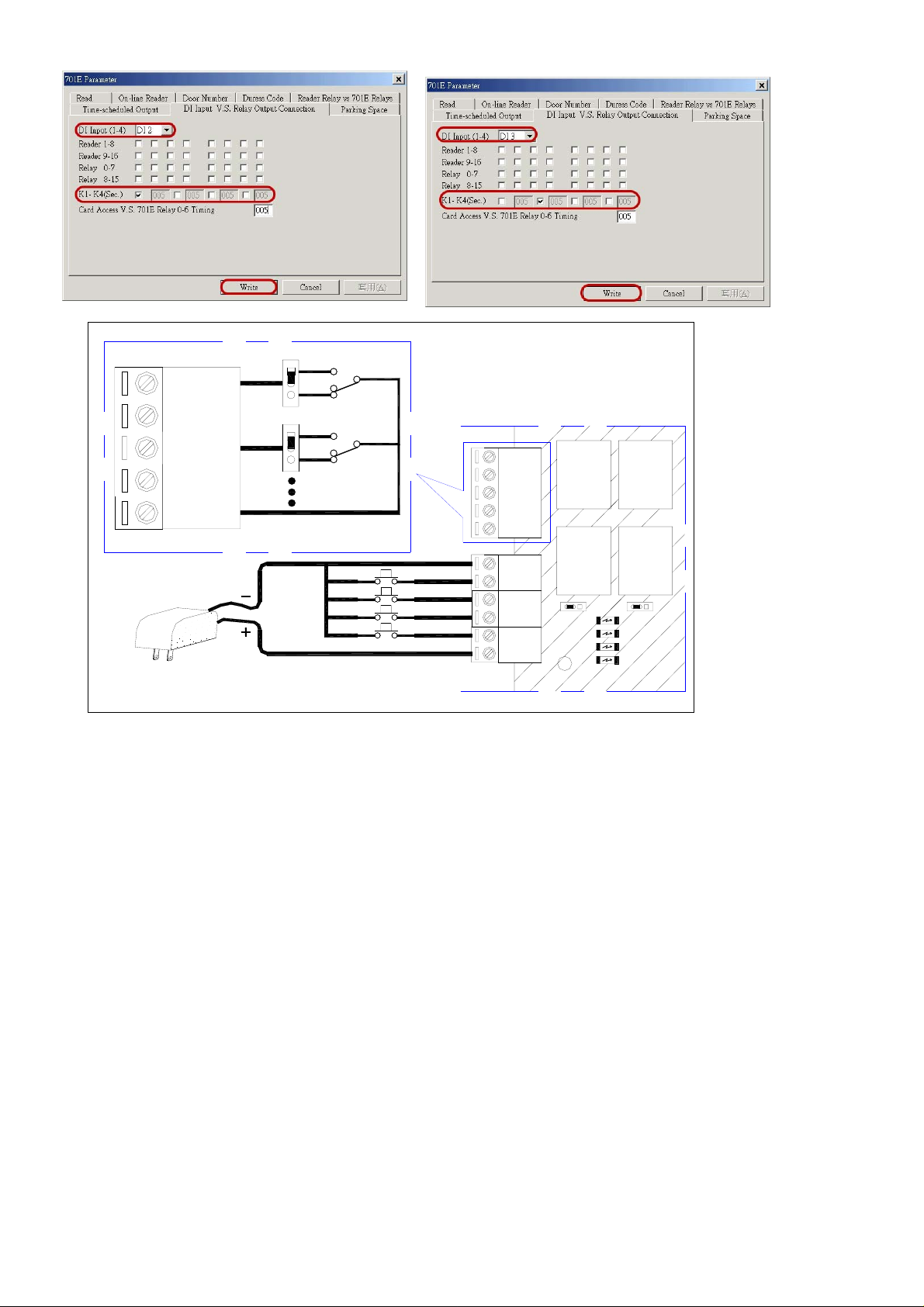
Step5: Click the page of DI Input V.S. Relay Output Connection.
2
Page 4
CN4
K1
K2
K3
K4
COM
CN4
K1
K2
K3
K4
COM
RELAY
K1
RELAY
K2
COM
DI.4
DI.3
DI.2
DI.1
V12
RELAY
JP4
D10
CN5
K3
RELAY
K4
D12
D11
D9
3.3 DI Input V.S. Relay Output Connection setting of 701E Parameter
1. The DI.2 is exit button input of reader port 1 and the K1 is open door relay.
(1) Choose “DI 2” under the menu item.
(2) Click “K1”.
2. The DI.3 is exit button input of reader port 2 and the K2 is open door relay.
(1) Choose “DI 3” under the menu item.
(2) Click “K2”.
Note: Active second can be set only when the window is DI 1.
3.4 Weigand reader LED and Buzzer indicators
1. LED light green and one beep sound mean acknowledge, LED light green twice and two beep
sounds mean not acknowledge.
2. In anti-pass-back access mode, LED light green five times and five beep
sounds mean violates access function.
3. When access modes have entering user code, after flash card, LED light green four times and four
beep sounds mean that reader wait for being entered the 4-digit user code.
3
Page 5
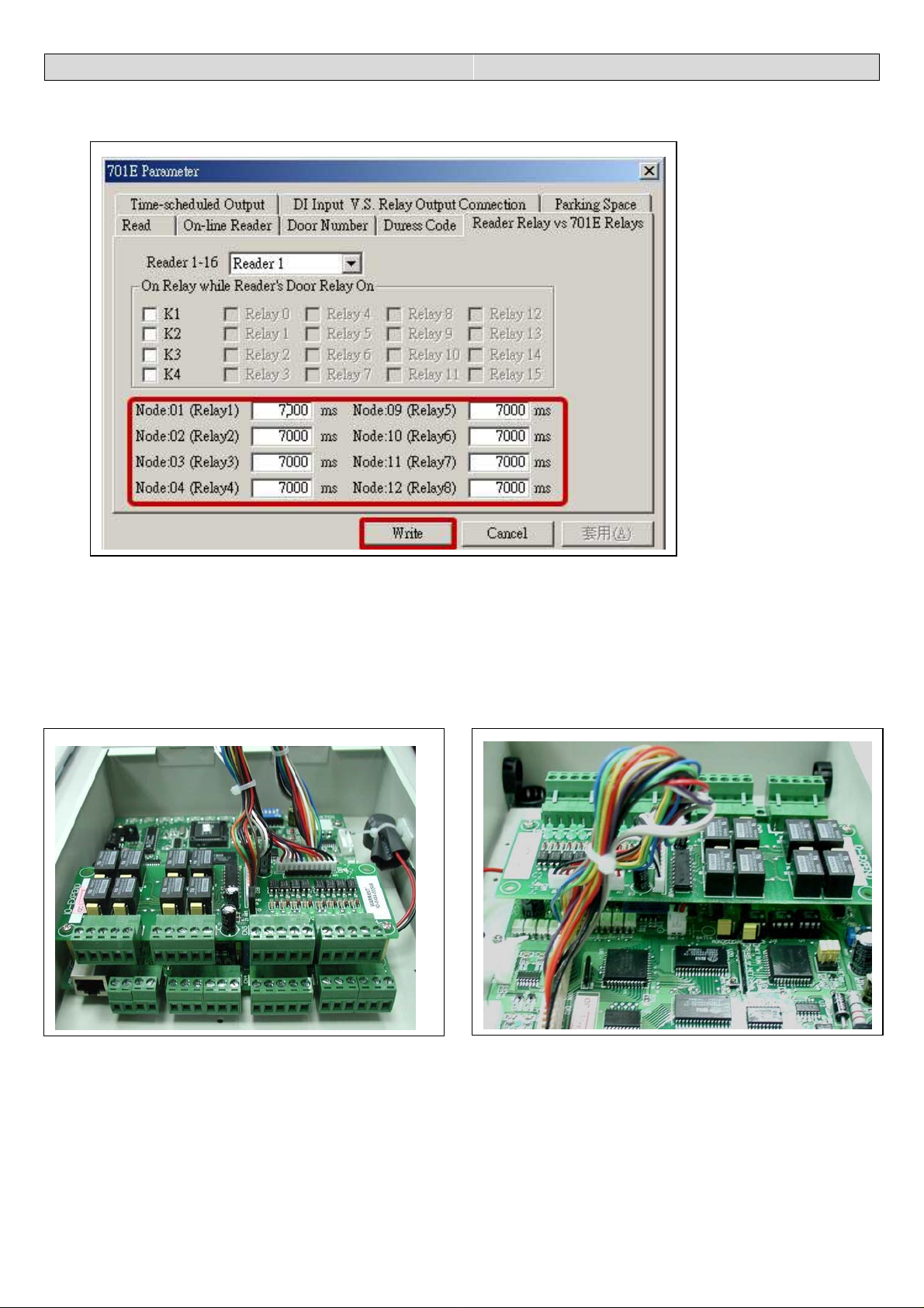
4. AR-716E-IO Software Setting (Optional)
4.1 Set relay time
Step1: Click the page of Reader Relay V.S. 701E Relays
Step2: Enter relay time in the blank column. Range from 0 to 60,000. (Default 7 sec.)
Step3: Press [ Write ].
4.2 AR-716E-IO hardware installation
Step1: Take away each screw on the top left and on the down left of AR-716EV2 \ 716Ei PCB board.
Step2: Screw copper column to fix AR-716E-IO PCB board.
Step3: Then, screw tightly copper column by using screw before take away.
Step4: Connect plug DB1 of AR-716E-IO to socket DB1 of AR-716EV2 \ 716Ei PCB board.
Connect plug DB2 of AR-716E-IO to socket DB2 of AR-716EV2 \ 716Ei PCB board.
4
Page 6
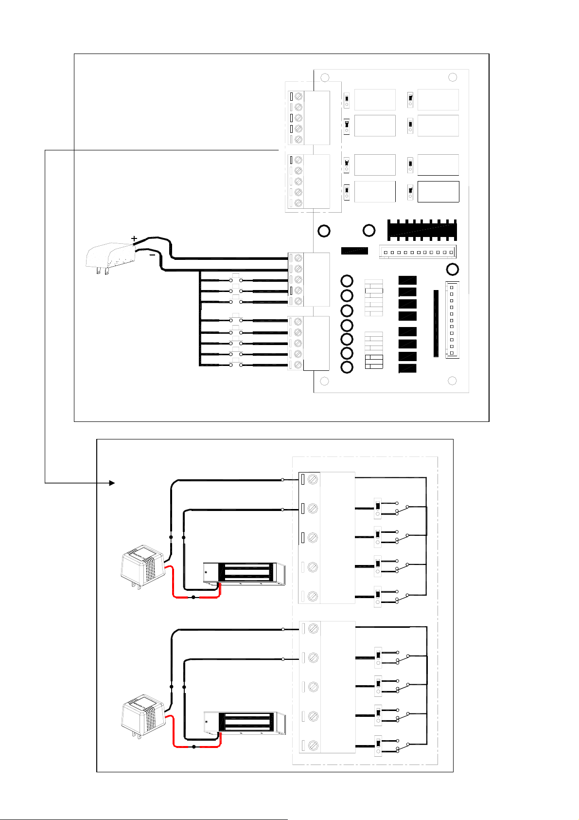
4.3 Push Button & Lock installation
CN 1
C O M
K1
K2
K3
K4
CN 2
C O M
K 5
K 6
K 7
K 8
COM
1
2
3
4
COM
5
6
7
8
I O - E X P E N D
K1
NO
R E L A Y
K1
NC
NO
R E L A Y
K 3
NC
K3
K5
NO
R E L A Y
K 5 K 6
NC
NO
R E L A Y
K 7
NC
K7
K2
NO
NC
NO
NC
K4
K6
NO
NC
NO
NC
K8
R E L A Y
K 2
R E L A Y
K 4
R E L A Y
R E L A Y
K 8
CN 3
Node 12
Node 11
Node 10
Node 9
Node 4
Node 3
Node 2
Node 1
V+
GND
8
7
6
5
4
3
2
1
CN 4
D B 2
D B 1
Push Button Door Exit
ECL-ACC1010
CN1
COM
K1
Power Supply
+12VDC 2A
-GND
+12VDC
Lock (-GND)
Magnetic Lock
Lock (+12VDC)
K2
K3
K4
CN2
COM
K5
-GND
Lock (-GND)
Power Supply
+12VDC 2A
+12VDC
Lock (+12VDC)
Magnetic Lock
5
K6
K7
K8
Page 7

5. AR-727i Configuration
5.1 Reset to Factory Default of the AR-727i
Press RESET button more than 5 seconds,
then AR-727i will restore to Factory Default value.
IP Address : 192.168.001.127
Gateway IP : 192.168.001.254
Subnet Mask : 255.255.255.000
Serail Port : 9600,N,8,1
TCP Port : 1621
Password : none
5.2 DIP Switch Settings
5.3 AR-727i’s contains three LED indicators, as described in the following table
Switch 1
Switch 2
Description
DHCP Function
AR-727i support Auto Configuration of the IP and
gateway addresses and subnet mask function, but
must make sure the DHCP Server is active.
Serial Setup Mode
ACT
BUSY
LINK
AR-727i
LED Name LED Color LED Function
Link
Yellow Media is connected.
Off Media is not connected.
ACT
Green 10 Mbps Ethernet connection.
Off Ethernet cable is disconnected,
or has a short.
BUSY
Red Configuration Setup.
Off No.
6
Page 8

5.4 How to set IP address on the AR-716Ei
5.4.1 Get IP address by using Net727i software
Usually, the network of some company don’t built-in the DHCP Server. Therefore, we can use the
following method to get default IP address and modify it. The steps as follows:
Step 1: Press RESET button more than 5 seconds, The BUSY LED will flash 5 times, then AR-727i
will restore to Factory Default value.
Step 2: Open explorer, click “My Network Places” and press right key to open Properties.
Step 3: Click “Local Area Connection” and press right key to open Properties.
Then double click Internet Protocol (TCP/IP) to open Properties.
7
Page 9

Step 4: Click ”Use the following IP address” and enter IP address 192.168.001.64,
Subnet mask 255.255.255.0
Step 5: Click “ok” to exit.
Step 6: Install Net727i.exe into your PC and run Net727i.exe
(Start → Programs → soyal software → Net727i )
8
Page 10

Step 7: Click “Get” to get default Local IP Address, Gateway, Netmask and TCP Port.
Step 8: Change new address and parameters then click “write”.
Step 9: switch DIP SW-1 and SW-2 to “OFF” position.
Remark:
(1) How to know PC’s IP Address? (Win98)
Start → execute → enter “winipcfg”.
(2) How to know PC’s IP Address? (Win2000)
Start → Programs → Accessories → Command Prompt → C:\> ipconfig
(3) Please see detailed parameter in next page:
9
Page 11

Setting Value Notes Necessity
Local IP Address 192.168.001.127 Defines own IP Address of the
AR-727CM
Local Gateway IP
Address
192.168.001.254 Defines the IP Address of the default
gateway
Local Subnet Mask 255.255.255.000 Defines the IP Address range for the
local network segment
TCP Port 1621 The TCP port that other devices must
use to contact this device. To avoid
conflicts with standard TCP ports.
MAC Address 00.E0.4C.00.00.50The MAC (Media Access Control)
address is a unique identifier set at the
factory.
Force Transmit time 5 Forces AR-727CM device’s TCP/IP
protocol software to try to pack serial
data received during the specified time
into the same data frame.
Required
Required
Required
Required
-
Optional
Force Transmit Bytes 32 Defines the amount of data in the
Optional
serial, Ethernet buffer at which the
break condition will be generated and
the contents of buffer will be sent out
via the Ethernet port.
Lock Remote IP
Address
Lock Serial Port
(Free Run or Freeze
Over)
- Allows contact with only the specified
remote IP address.
- To avoid the hacker use this IP to
intercept data when Remote IP
Address doesn’t receive data.
Optional
Optional
Setup Password none Console password Optional
Serial Port Speed 9600 Changes current baud rate of the
Required
AR-727CM’s serial port (from 2400bps
to 57600bps).
TCP Auto Disconnect
Time
60 This device automatically closes TCP
connection if there is no TCP activity
Optional
(Second)
Serial Port Hardware
Handshaking
(RTS/CTS)
- An exchange of signal over specific
for the given time.
wires which each device indicates its
readiness to send or receive data.
DHCP - Selecting the enable option allows
DHCP to automatically assign the
AR-727CM’s IP address.
10
Optional
Optional
Page 12

5.5.2 Get IP address by DHCP Server:
AR-727i support Auto Configuration of the IP and gateway addresses and subnet mask function,
but must make sure the DHCP Server is active. The steps as follows:
Step 1: Power off.
Step 2: PCB diagram as follows by using DHCP Function.
Switch DIP SW-1 to “ON” position.
Switch DIP SW-2 to “OFF” position.
Switch Jumper J3, J4 and J5 to Net position.
No IC Chip in the U3 position.
Step 3: Power on. In begging state the ACT LED will flashing, after IP has got ACT LED will off
and auto save the new IP address to EEPROM.
Step 4: Power off.
Step 5: Change communication IC Chip from the “U2” position to the “U3” position.
Step 6: Then, Switch DIP SW-1 to “OFF” position and Switch DIP SW-2 to “ON” position.
( return to Serial Setup Mode)
Step 7: Connect AR-801CM to the HOST of the PCB.
Step 8: Power on.
Step 9:To modify parameter on the AR-727i through the Hyper-Terminal function of the Window.
(Start → Programs → Accessories → Communication → Hyper Terminal)
11
Page 13

Step 10: Click “Hyper-Terminal”. Step 11: key-in any temporary name.
Shown as follows: It is not important matter.
Step 12: Choose which COM port that Step 13: Set Port Settings to 9600, 8, None, 1,
AR-801CM connect and click OK to exit. None and click “OK” to save.
12
Page 14

Step 14: AR-727i already gets IP address now shown as follows:
Note that save it after set all parameters.
Step 15: Power off. Then switch DIP SW-2 to “OFF” position, take away communication IC Chip
on the U3 position of the PCB and AR-801CM.
13
Page 15

5.5.3 Get IP address by AR-801CM (COM Port) connects to PC
At first, PCB diagram as follows and Connect AR-801CM to the HOST of the PCB:
Switch DIP SW-1 to “OFF” position.
Switch DIP SW-2 to “ON” position. (Serial Setup Mode)
Switch Jumper J3, J4 and J5 to RS-485 position.
Make sure that have communication IC Chip in the U3 position.
14
Page 16

Step 1: To modify parameter on the AR-727i through the Hyper-Terminal function of the Window.
(Start → Programs → Accessories → Communication → Hyper Terminal)
Step 2: Click “Hyper-Terminal”. Step 3: key-in any temporary name.
Shown as follows: It is not important matter.
Step 4: Choose which COM port that Step 5: Set Port Settings to 9600, 8, None, 1,
AR-801CM connect and click OK to exit. None and click “OK” to save.
15
Page 17

Step 6: AR-727i already gets IP address now shown as follows:
Step 7: Please refer above item and enter item on the so that set all parameters.
Step 8: Note that enter item 6 on the to save parameter after finishing to set parameter.
Step 9: Then switch DIP SW-1 and SW-2 to “OFF” position.
16
Page 18

6. Installation diagram
6.1 AR-716Ei and AR-721H networking installation
2
641
16
3
4
12345678
ON
128
832
2
ON
1
ON
Power
Reset
Channel 2 RX
Channel 2 TX
Channel 1 TX
Channel 1 RX
Host RX
Host TX
Node
1
3246587
N
O
3
001
Busy
1
JP5
2
Battery
AR-716Ei
002
1+2~1+32
ON
003
PORT2
PORT1
ON
~
033
Pink / Gray BZ
Brown / Brown LED
Blue / Blue D1
Green / Green D0
Black / Black GND
Red / Red 12V
Purple / Gray BZ
Brown / Brown LED
Blue / Blue D1
Green / Green D0
Black / Black GND
Red / Red 12V
Node:
AR-721K
or
AR-721U
K1
K2
RELAYRELAY
K1
K3K4K2
COM
AR-727i
CN2
CN1
Vin
Vin
BV+
CN3
BV-
CH2
CH1
JP2
JP1
HOST
Ethernet
1
CN4
K4
RELAY
K3
RELAY
DI.4
COM
DI.3
JP3
D12
DI.2
D11
D9
D10
JP4
Normal mode
JP5
1-2 On:RUN
2
3
1
DI.1
V12
CN5
2-3 On:Clear
(Must Power OFF)
Reset to default value
2
3
1
JP5
2
DC15V
~~
Next
Controller
~
AR-721H4
AR-721H4
~~
Power Must higher than 13.8VDC
Battery
Node: 009
To
To
Node: 001
Node: 016
~
AR-801CM
K1
~~
To PC
Node: 008
DC12V
CN4
1
K2
K3
K4
COM
17
Page 19

6.2 AR-716EV2 and AR-721H networking installation
ON
2
002
1+2~1+32
ON
003
ON
~
6414
16
3
12345678
ON
128
832
2
1
ON
Power
Channel 2 RX
Reset
Channel 2 TX
Channel 1 RX
Channel 1 TX
Host RX
Host TX
Node
1
3246587
O
N
3
001
Busy
PORT2
JP5
1
2
Battery
AR-716EV2
PORT1
JP3
K4
RELAY
RELAY
COM
K3
DI.4
D12
DI.3
JP4
DI.2
D11
D10
DI.1
D9
V12
CN5
JP5
2
Vin
727i
JP2
CH1
JP1
HOST
CN3
BV-
BV+
CH2
K2
RELAYRELAY
K1
K4
K3
K2
K1
1
COM
CN4
CN2
CN1
Vin
Ethernet
033
Node:
Pink / Gray BZ
Brown / Brown LED
Blue / Blue D1
Green / Green D0
Black / Black GND
Red / Red 12V
Purple / Gray BZ
Brown / Brown LED
Blue / Blue D1
Green / Green D0
Black / Black GND
Red / Red 12V
2-3 On:Clear
(Must Power OFF)
Reset to default value
2
3
1
JP5
AR-721K
or
AR-721U
Normal mode
1-2 On:RUN
2
1
3
DC15V
AR-721H4
~
~
Node: 009
AR-721H4
~~
To
Node: 016
Node: 001
To
Node: 008
Power Must higher than 13.8VDC
~~
Battery
AR-801CM
~~
Next
Controller
DC12V
To PC
18
1
K1
K2
CN4
K3
K4
COM
Note that the connecting distance between AR-801CM and the PC cannot be more than 2 meter.
Page 20

6.3 Points for attention
1. Please use the following installation method, it is correct.
801CM
OR
Controller
2. Don’t use the following installation method, it will cause communication error.
Controller
OR
801CM
OR
Controller
3. We suggest using the following cable in RS-485 communication
Controller
OR
Reader
19
Please screw snake
net on the controller.
 Loading...