

Page 1
®
Copyright by SOYAL Technology Co., Ltd.. All rights reserved.
SOYAL
ACCESS CONTROL SYSTEM
Contents
NET
2
JP3
JP4
JP5
654321654321
1
Products
Installation
Wall Surface
Use Appropriate Fasteners
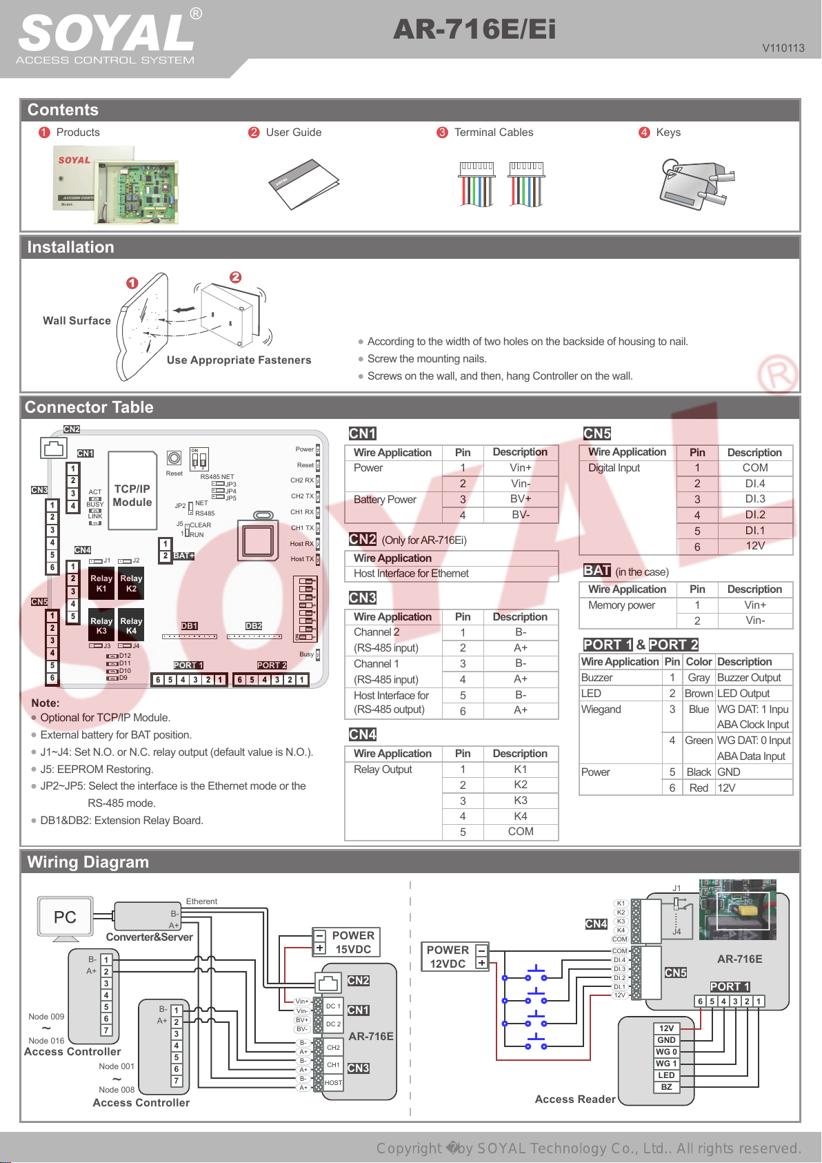
Connector Table
CN2
CN1
1
2
CN3
CN5
3
1
4
2
3
4
5
1
6
2
3
4
1
5
2
3
4
5
6
CN4
ACT
BUSY
LINK
Relay
Relay
J1
K1
K3
J3
TCP/IP
Module
J2
Relay
K2
Relay
K4
J4
D12
D11
D10
D9
Note:
Optional for TCP/IP Module.
External battery for BAT position.
J1~J4: Set N.O. or N.C. relay output (default value is N.O.).
J5: EEPROM Restoring.
JP2~JP5: Select the interface is the Ethernet mode or the
RS-485 mode.
DB1&DB2: Extension Relay Board.
ON
2
1
Reset
RS485
NET
JP2
RS485
J5
CLEAR
1
RUN
1
BAT+
2
BAT+
DB1 DB2
User Guide
CH2 RX
CH2 TX
CH1 RX
CH1 TX
Host RX
Host TX
PORT 2PORT 1
Power
Reset
ON
Busy
According to the width of two holes on the backside of housing to nail.
Screw the mounting nails.
Screws on the wall, and then, hang Controller on the wall.
CN1
Wire Application
Power
Battery Power
CN2
Wire Application
Host Interface for Ethernet
678
CN3
5
Wire Application
234
Channel 2
1
(RS-485 input)
Channel 1
(RS-485 input)
Host Interface for
(RS-485 output)
CN4
Wire Application
Relay Output
AR-716E/Ei
3
Terminal Cables
Description
Pin
1
2
3
4
(Only for AR-716Ei)
Pin
1
2
3
4
5
6
Pin
1
2
3
4
5
Vin+
Vin-
BV+
BV-
Description
B-
A+
B-
A+
B-
A+
Description
K1
K2
K3
K4
COM
4
CN5
Wire Application
Digital Input
BAT
(in the case)
Wire Application
Memory power
PORT 1 PORT 2&
Wire Application
Buzzer
LED
Wiegand
Power
Keys
Pin
1
2
3
4
5
6
Pin
1
2
3
4
5
6
Pin
1
2
Color
Gray
Brown
Blue
Green
Black
Red
V110113
Description
COM
DI.4
DI.3
DI.2
DI.1
12V
Description
Vin+
Vin-
Description
Buzzer Output
LED Output
WG DAT: 1 Inpu
ABA Clock Input
WG DAT: 0 Input
ABA Data Input
GND
12V
Wiring Diagram
Converter&Server
B-
1
A+
2
3
4
Node 009
~
Node 016
Access Controller
5
6
7
Node 001
~
Node 008
Access Controller
Etherent
B-
A+
POWER
15VDC
POWER
12VDC
CN2
Vin+
B-
1
A+
2
3
4
5
6
7
Vin-
BV+
COM
BV-
DC 1
CN1
DC 2
CH2
CH1
HOST
AR-716E
CN3
B-
A+
B-
A+
B-
A+
CN4
COM
COM
DI.4
DI.3
DI.2
DI.1
12V
K1
K2
K3
K4
J1
J4
AR-716E
CN5
PORT 1
654321
12V
GND
WG 0
WG 1
LED
BZ
Access Reader
Page 2
Multi-Door Networking Controller
Copyright by SOYAL Technology Co., Ltd.. All rights reserved.
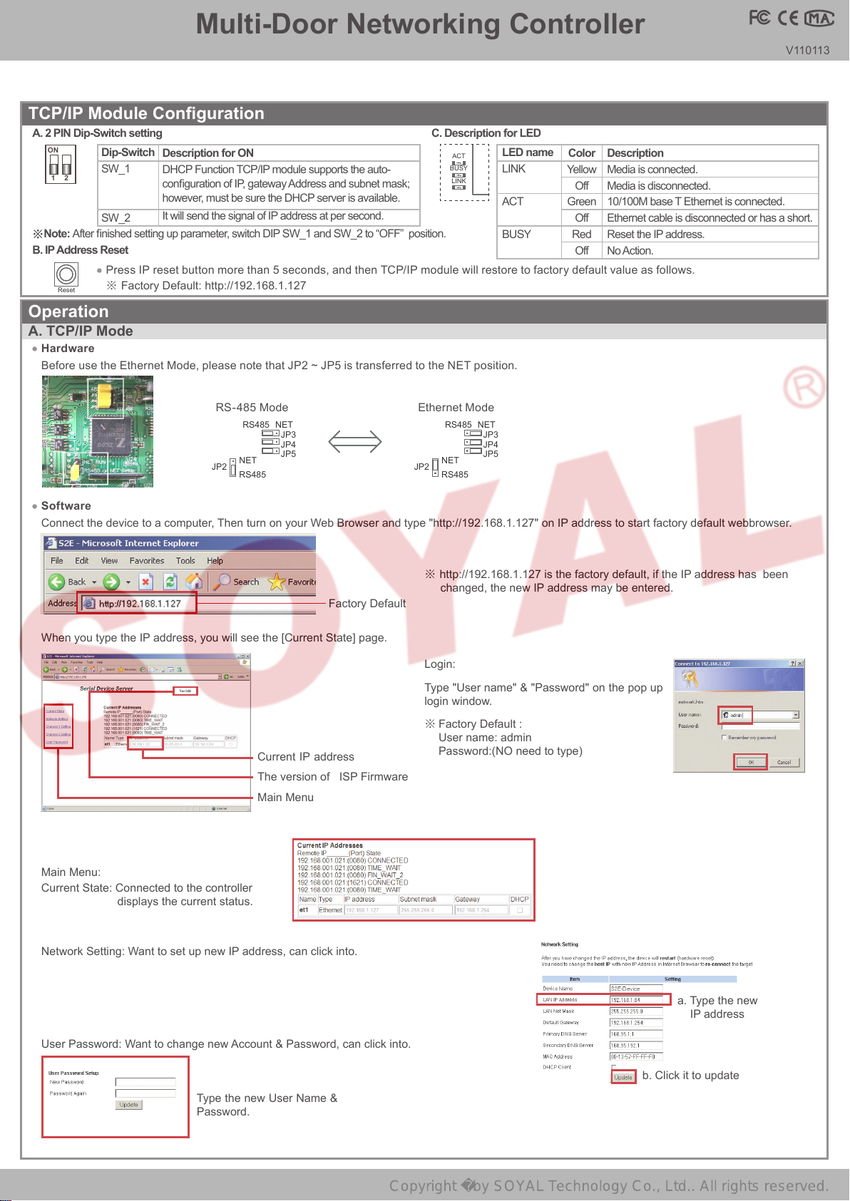
TCP/IP Module Conguration
A. 2 PIN Dip-Switch setting
ON
1
2
Dip-Switch
SW_1
Description for ON
DHCP Function TCP/IP module supports the auto-
conguration of IP, gateway Address and subnet mask;
however, must be sure the DHCP server is available.
SW_2
Note: After nished setting up parameter, switch DIP SW_1 and SW_2 to “OFF” position.
※
It will send the signal of IP address at per second.
B. IP Address Reset
Press IP reset button more than 5 seconds, and then TCP/IP module will restore to factory default value as follows.
Factory Default: http://192.168.1.127
Reset
Operation
※
A. TCP/IP Mode
Hardware
Before use the Ethernet Mode, please note that JP2 ~ JP5 is transferred to the NET position.
NET
RS485
JP3
JP4
JP5
NET
JP2
RS485
C. Description for LED
ACT
BUSY
LINK
Ethernet ModeRS-485 Mode
RS485
NET
JP2
RS485
NET
JP3
JP4
JP5
LED name
LINK
ACT
BUSY
Description
Color
Media is connected.
Yellow
Media is disconnected.
Off
10/100M base T Ethernet is connected.
Green
Ethernet cable is disconnected or has a short.
Off
Reset the IP address.
Red
No Action.
Off
V110113
Software
Connect the device to a computer, Then turn on your Web Browser and type "http://192.168.1.127" on IP address to start factory default webbrowser.
http://192.168.1.127 is the factory default, if the IP address has been
※
changed, the new IP address may be entered.
Factory Default
When you type the IP address, you will see the [Current State] page.
Login:
Type "User name" & "Password" on the pop up
login window.
Factory Default :
※
User name: admin
Current IP address
Password:(NO need to type)
The version of ISP Firmware
Main Menu
Main Menu:
Current State: Connected to the controller
displays the current status.
Network Setting: Want to set up new IP address, can click into.
User Password: Want to change new Account & Password, can click into.
Type the new User Name &
Password.
a. Type the new
IP address
b. Click it to update
Page 3

SOYAL
Copyright by SOYAL Technology Co., Ltd.. All rights reserved.
ACCESS CONTROL SYSTEM
®
AR-716E/Ei
V110113
B. Node ID setting
The hardware setup is complete, the software can be set.
※
Hardware
Power Off
Re-apply the power
→
2 8 32 128
ON
2345678
1
1 4 16 64 2
Take off the battery connector from [BAT+] socket
→
Node: 002 Node: 003 Node: 007 Node: 008
[e.g.]:
ON
2345678
1
ON
2345678
1
1+2 1+2+4 8
Set up node number by 8 dip-switch
→
ON
2345678
1
ON
2345678
1
→
Software
Open the "701 Server" Software → There are two ways to open the Communication Port setting window: and
1.
Communication Port Setting
→
a
b
c
e
d
After COM Port setting, there are two ways to open the Node Number for Polling window: and
2.
Node Number for Polling
→
a. By the computer Detection results to select the por t. (Use the RS- 485)
b. Select [TCP/IP Oonly]. (Use the Ethernet)
c. Selection the options: Polling Message From Controller.
d. Polling Inter val: 200ms, PC every 200ms inquiries once access controller's messages.
e. Press YES
f. Selection node ID (for example:001) and access controller
f
g
h
j
i
g. If use the Ethernet mode, please check the "IP"; if use the RS- 485 mode don't need to check.
h. If use the Ethernet mode, input IP in "IP Address" eld. (Default value: 192.168.1.127)
k
i. Input 1621 in "Por t" eld.
(Default value: 1621; these Port number is SOYAL designed for connection to the network.)
j. Selection LAN BASE.
k. Press YES
Plug in battery connector
3.
Open Controller On/Off Line window to check the device connection status:
4.
Download real time clock to AR-716E by clicking.
5.
Setting up AR-716E parameters:
There are two ways to open the 701E Parameter window: and
a
a. There is lled in AR-716E node ID to get in 716E parameter for others setting.
b
d
c
b. Setting up "On-line Reader" of readers
c. AR-716E rmware version
d. Current readers connected with AR-716E.
Node ID of reader must be ticked, or it will show disconnected.
※
e
f
g
h i
e. Setting up "Door Number" of readers
f. The RS- 485 Access Controllers connector to the "Channel 1" of the [CN3]
g. The RS- 485 Access Controllers connector to "Channel 2" of the [CN3]
h. The Access Reader connector to the [PORT 1]
i. The Access Reader connector to the [PORT 2]
Setting up door number of readers Each door number should be unique.
※
→
Well: controller successfully connected to PC.
Not connected well: recommends the
following checks.
CN3
CH 2
CH 1
PORT 2PORT 1
Page 4

Multi-Door Networking Controller
Copyright by SOYAL Technology Co., Ltd.. All rights reserved.
C. Restoring Factory Settings
EEPROM Restoring
Power Off
back to “RUN”position
IP Address Reset
Shift 2 dip-switch of TCP/IP module to “OFF” → Press IP reset button more than 5 seconds
factory default value as follows
Factory default value of IP Address
IP Addre ss: 192.168.1.127
Gateway IP : 192.168.1.254
Subnet M ask: 255 .255 .255 .0
D. About LED (right of the PCB)
POWER
When the controller is connected to the power, [POWER] will turn from green LED; if no light, mean the power supply have problems.
RESET
After "EEPROM Restoring", [RESET] will ash the red LED and then clear the memory before the action started.
CH2 RX & CH2 TX
[CH2 RX] receive Access Controllers Node 9 ~ Node 16 of the information on behalf of each ash a green LED
to receive a data controller.
[CH2 TX] send data to the Access Controllers Node 9 ~ Node16, will ash red LED.
CH1 RX & CH1 TX
[CH1 RX] receive Access Controllers Node 1 ~ Node 8 of the information on behalf of each ash a green LED
to receive a data controller.
[CH1 TX] send data to the Access Controllers Node 1 ~ Node8, will ash red LED.
[e.g.] How to nd the external Access Controllers have problem, from the LED.
Because the default value [Node 1] and [Node 9] are checked, so [CH1 TX] and [CH2 TX] will continue to ash, when there are not
※
external the Access Controller.
Take off the battery connector from [BAT+] socket
→
Plug in battery connector
→
Serial Port: 9 600, N, 8, 1
TCP Port: 1621
Passwor d: None
→
Re-apply the power
[J5] jumper shift to “Clear” position for 15 seconds
→
Done
→
TCP/IP module will restore to
→
If "Channel 1" external 6 Access Controllers, under normal circumstances [CH1 RX] will always
be in twinkle.
LED ash frequency: twinkle, twinkle, twinkle, twinkle, twinkle, twinkle......
If LED ash frequency become: twinkle, no, twinkle, no, twinkle, twinkle......
It means the Node 2 and Node 4 have problem.
→
ON
1
Shift [J5]
2
V110113
J5
BAT+
Reset
HOST RX & HOST TX
[HOST RX] sent by the host PC to receive incoming data, the connection has been blinking green LED.
[HOST TX] to send data to PC host, the connection will remain after the red LED ashes.
BUSY
When the red LED is lit, the memory is running clear and restores the factor y default
action.
If you do not per form "EEPROM Restoring", but the [RESET ] and [BUSY] has been
※
lit red, indicating a problem with PCB should be excluded.
E. About LED (lift of the PCB)
CN3
1
2
3
4
5
6
ACT
When the Ethernet mode is successful, [ACT] will be the green LED.
BUSY
After "IP Address Reset", [BUSY] will be the red LED, and restore to factory default value.
LINK
After Ethernet connect to [CN2], [LINK] will be the yellow LED.
If [LINK ] lit, but the [ACT] did not light up, indicating a problem with the Ethernet
※
CN5
1
2
3
4
5
6
connection to be excluded.
D9 ~D12
Representative [CN5] DI1 ~ DI4 on the output state; if "DI1" output signal, [D9] will light green LED.
CN2
1
2
3
4
1
2
3
4
5
CN1
CN4
ACT
BUSY
LINK
Relay
Relay
J1
K1
K3
J3
TCP/IP
Module
J2
Relay
K2
Relay
K4
J4
D12
D11
D10
D9
ON
2
1
Reset
RS485
NET
JP2
RS485
J5
CLEAR
1
RUN
1
BAT+
2
BAT+
DB1 DB2
NET
Power
Reset
JP3
JP4
JP5
654321654321
CH2 RX
CH2 TX
CH1 RX
CH1 TX
Host RX
Host TX
678
5
234
1
ON
PORT 2PORT 1
Busy
 Loading...