

Page 1
®
SOYAL
ACCESS CONTROL SYSTEM
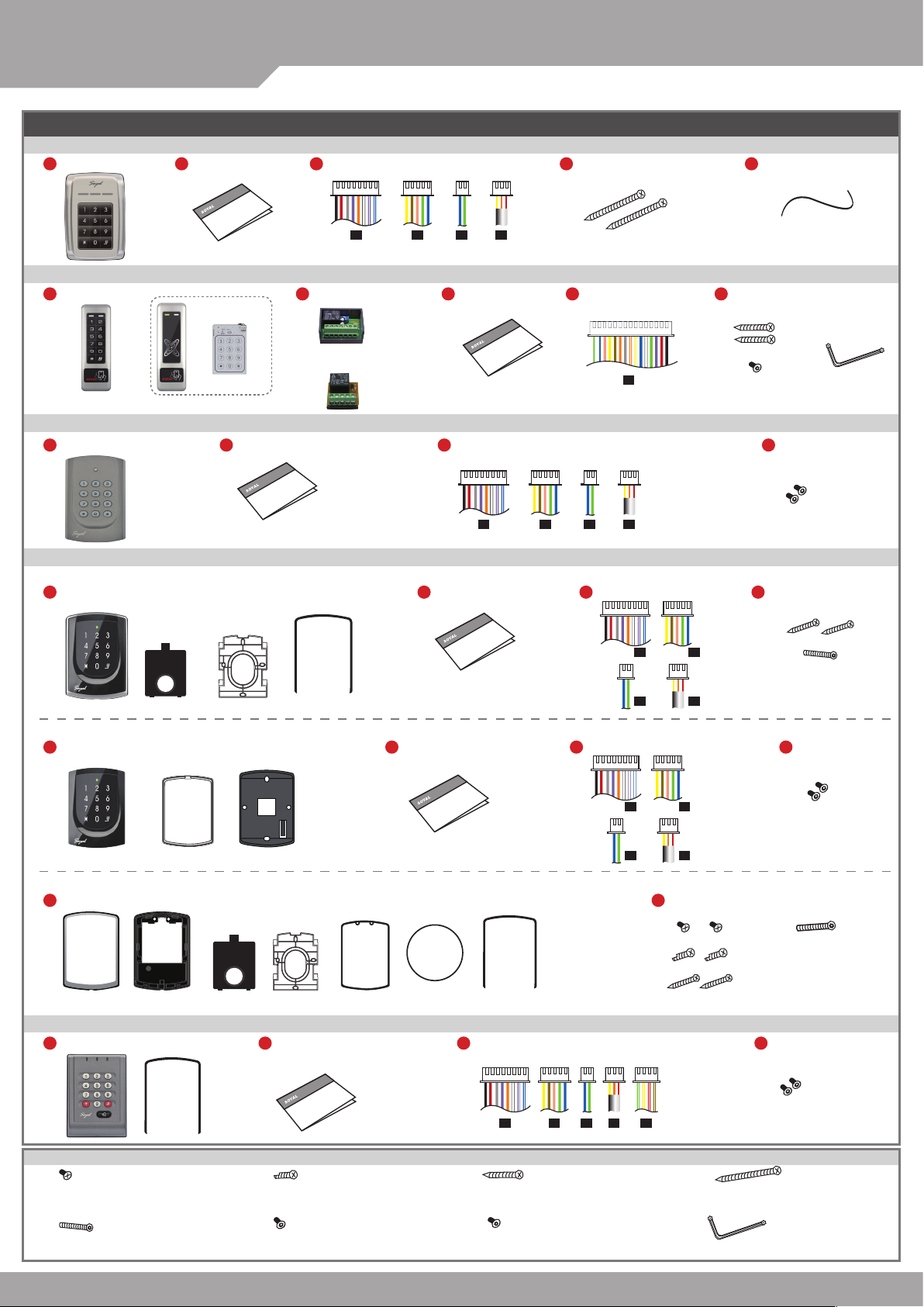
Contents
AR-321 (H): Touch-panel Metal Housing
1
Product
2
User Guide
AR-721(H) / AR-725 (H) / AR-757 (H)
AR-321 (H) / AR-331 (H) /
3
Terminal Cables
4
Tools
5
Water proof Strip
V140707
P1
P2
P3
P4
AR-331 (H): Touch-panel Metal Housing / AR-331 (H-S): Metal Housing
1
Product
or
WG keyboard
AR-331 (H) AR-331 (H-S)
[Optional]
2
Optional
AR-721RB
Digital Relay
or
AR-821RB
Original Relay
3
User Guide
AR-721 (H)
1
Product
2
User Guide
3
Terminal Cables
P1
AR-725 (H): Illuminated Touch-panel
AR-725 (H-M)
1
Products
A.
B.
C.
D.
2
User Guide
AR-725 (H)
1
Products
2
User Guide
d x2
Additional external relay must be purchased.
※
4
Terminal Cables
P7
P2
P3
P4
3
Terminal Cables
P1
P3
3
Terminal Cables
5
Tools
c x2
g x1 h x1
4
Tools
f x2
4
Tools
P2
P4
4
c x2
e x1
Tools
A1.
E.
AR-725 (X)
1
Products
A2. A3.
AR-757 (H)
1
Product
Parts Description
a.
Button Head Pozidriv
Tapping Screw: M3x10
e. f.
Security Torx Screw:
M3.5x15
P1
F.
B.
C. H.G. D.
2
User Guide
b. c. d.
Button Head Pozidriv
Slotting Screw: 2.5x10
Flat Head Hex Socket
Screw: M3x8
3
Terminal Cables
P1
Flat Head Cap Philips
Tapping Screw: 4x19.1
g. h.
Security Torx Screw: M3x10 Security Torx Wrenches
P2
P3
P3
P4
P2
P4
2
Tools
a x2
b x2
c x2
4
Tools
P6
Flat Head Cap Philips
Tapping Screw: 4x38
f x2
e x1
f x2
Page 2
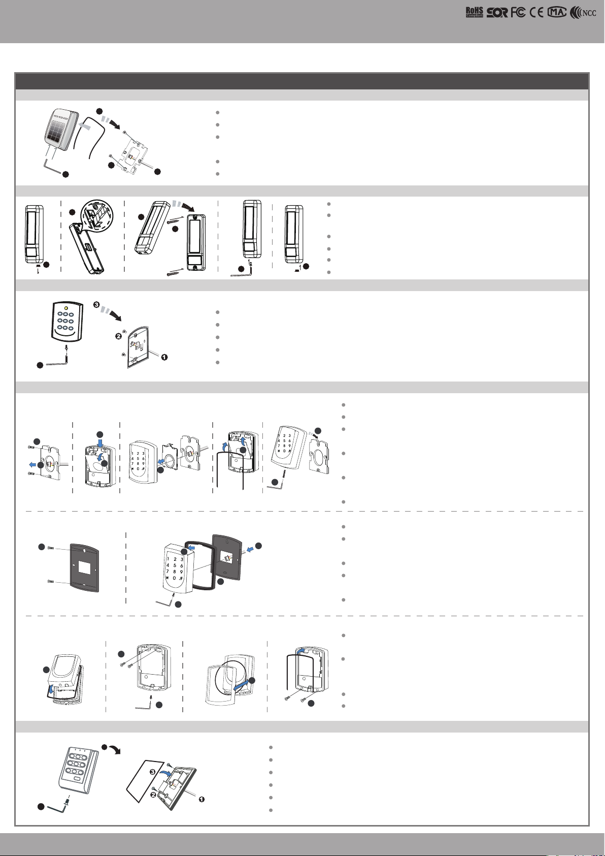
Installation
AR-321 (H)
3
2
4
AR-331 (H) / AR-331 (H-S)
2
1
AR-721 (H)
4
Access Controller
Touch-panel Metal Housing / Illuminated Touch-panel
Pull the cables from the square hole of the mounting plate.
Use a screwdriver to screw the mounting plate onto the wall.
Attach the water proof strip to the body, then connect the terminal cables to the body and attach the
body to the mounting plate.
1
4
3
Use the Allen key and screws (accessories supplied) to assemble the body onto the mounting plate.
Turn on the power, and LED will light and beep will sound.
Remove the rubber plug.
To cut tamper-resistant column and make it fit the appropriate
height for actual installation.
First, take off the metal casing then screw the controller on the wall.
Second, put the metal casing back and lock it with security screw.
Finally, put the rubber plug into the hole.
5
Pull the cables from the square hole of the mounting plate.
Pull the cables from the square hole of the mounting plate.
Use a screwdriver to screw the base onto the wall.
Use a screwdriver to screw the base onto the wall.
Connect the terminal cables to the body and attach the body to the mounting plate.
Connect the terminal cables to the body and attach the body to the mounting plate.
Assemble the covers with the Allen key and screws (accessories supplied).
Assemble the covers with the Allen key and screws (accessories supplied).
Turn on the power and LED will light and beep will sound.
Turn on the power and LED will light and beep will sound.
6
Turn on the power, and LED will light and beep will sound.
V140707
AR-725 (H)
AR-725 (H-M)
2
C.
1
c.
AR-725 (H)
1
AR-725 (X)
A1.
1
G.
Pull the cables from the square access hole of the mounting plate C.
Use a screwdriver to screw the metal plate C onto the wall.
3
A.
A.
4
B.
B.
5
A.
C.
B.
A.
6
8
D.
7
Take off the plastic mounting plate B from the body A, and pull the cables
through the access hole of C and B, then connect to the body A.
C.
Assemble plate B with the body A, and embed the water proof strip D
d.
onto the plastic side frame.
Assemble the body A onto the mounting plate C with the Allen key and
screws (accessories supplied).
Turn on the power and LED will light and beep will sound.
E.
F.
A1.
3
F.
2
Use a screwdriver to screw the base F onto the wall.
Attach the water proof gasket to the body A1, and pull the cables
from the square hole of the base F, and connect to the body A1.
Assemble the body A1 with the base F.
4
e.
5
Screw A1 and F tight with the Allen key and screws (accessories
supplied).
Turn on the power and LED will light and beep will sound.
Put on G, and attach A1 onto the plastic plate A3, and screw it with
the Allen key and screws (accessories supplied).
Put the ring O on the metal frame, and put them together onto the
reader A1+A3, and screw them and buckle up the 4 buckles on the
back.
Embed the water proof strip D onto the frame side of the base.
Following by the install process of AR-725 (H-M)
A3.
A2.
H.
A1.+A3.
2
b.
e.
3
D.
4
a.
5
AR-757 (H)
5
4
Pull the cables from the square hole of the mounting plate.
Use a screwdriver to screw the base onto the wall.
Embed the water proof strip 3 onto the frame side of the base.
Connect the terminal cables to the body and attach the body to the mounting plate.
Assemble the covers with the Allen key and screws (accessories supplied).
Turn on the power and LED will light and beep will sound.
Page 3
SOYAL
ACCESS CONTROL SYSTEM
Notice
1.Tubing:
2.Wire selection:
3.Power supply:
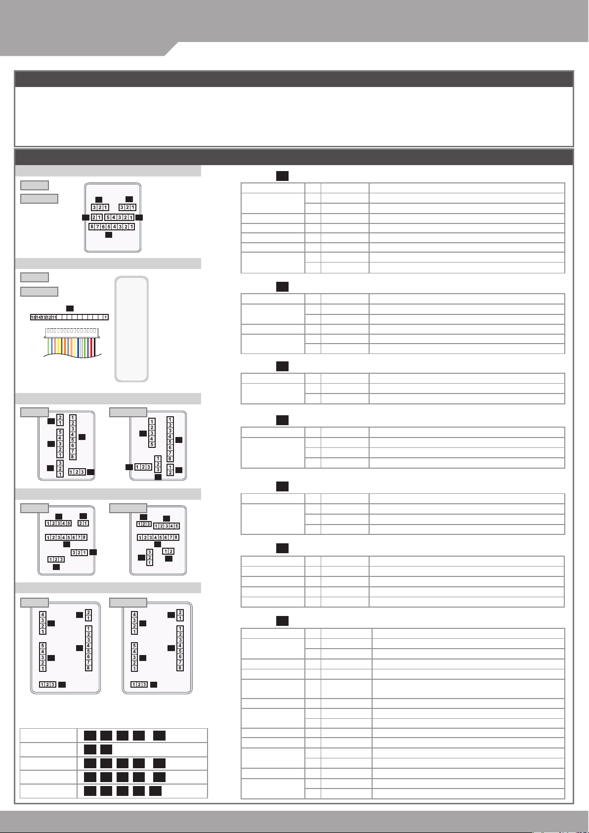
Connector Table
AR- 321H
AR-321 (H)
125kHz
13.56MHz
AR-331 (H) / AR-331 (H-S)
125kHz
13.56MHz
The communication wires and power line should NOT be bound in the same conduit or tubing.
Use AWG 22-24 Shielded Twist Pair to avoid star wiring.
Don’t equip controller and lock with the same power supply. The power for controller may be unstable when the lock is activating, that may make
the controller malfunction.
The standard installation: Door relay and lock use the same power supply, and controller use independent power supply.
P4
P3
P7
10 98765432
P5
P1
®
P2
AR-321 (H) / AR-331 (H) /
AR-721(H) / AR-725 (H) / AR-757 (H)
P1Cable :
Wire Application
Lock Relay
Common-COM-Point
Door contact
Exit Switch
Alarm Relay
Power
P2Cable :
Wire Application
Wiegand
Beeper
LED
Pin
Blue White
1
Purple White
2
3
4
5
6
Thick Red
7
Thick Black
8
Pin
1
Thin Blue
2
Thin Green
3
4
5
Color
White
Orange
Purple
Gray
Color
Pink
Brown
Yellow
Description
(N.O.) DC24V1Amp
(N.C.) DC24V1Amp
(COM) DC24V1Amp
Negative Trigger Input
Negative Trigger Input
Low output; Max 12V/100mA (Open Collector)
DC Power 12V
DC Power 0V
Description
Wiegand DAT:1 Input
Wiegand DAT:0 Input
Beeper Output 5V/100mA, Low
LED Green Output 5V/20mA, Max
LED Red Output 5V/20mA, Max
V140707
AR-721 (H)
125kHz
P3
P2
P4
P1
P5
13.56MHz
P4
AR-725 (H)
125kHz
P3
P2
P1
P4
13.56MHz
P5
AR-757 (H)
125kHz 13.56MHz
P3
P6
P1
P2
P4
Connectors Comparison
AR-321 (H)
AR-331 (H)
AR-721 (H)
AR-725 (H)
AR-757 (H)
P1 P2 P3 P4 (
P7 P8
P1 P2 P3 P4 (
P1 P2 P3 P4 (
P1 P2 P3 P4 P6
P3Cable :
Wire Application
Networking
Module
P4Cable :
P2
P1
P3
P5
Wire Application
Tamper Switch
P5Cable :
Wire Application
P5
P2
P1
P4
P3
P3
P6
P1
P2
P4
Optional
Optional
Optional
)P5
)P5
)P5
3-PIN Connector
P6Cable :
Wire Application
Doorbell
Arming
Duress
LED indicator
P7Cable :
Wire Application
Power
Exit Switch
Networking Module
Lock Relay
Networking Module
Tamper Switch
Alarm Relay
Door contact
LED
Beeper
Wiegand
Pin
Color
1
Thick Green
2
Thick Blue
(Contact Rating: 1A 125VAC/24VDC)
Pin
Color
1
Red
2
Orange
3
Yellow
(Optional)
Pin
Color
1
Black
2
White
3
Purple
Pin
Color
1
Brown White
2
Red White
3
Yellow White
4
Green White
(Directly connected at the Access controller)
Color
Pin
Thick Black
1
Thick Red
2
Purple
3
Thick Green
4
5
White
Thick Blue
6
Yellow White
7
Orange White
8
Gray
9
Orange
10
Brown
11
Yellow
12
13
14
15
Pink
Thin Blue
Thin Green
Description
RS-485(B-)
RS-485(A+)
Description
N.C.
COM
N.O.
Description
GND.
Duress
Arming/ Security trigger signal
Description
BE Output
AR Output/ Security trigger signal Output
DU Output/ TTL out
Hi input/ Green light brighten
Description
DC Power 0V
DC Power 12V
Negative Trigger Input
RS-485(B-)
Low output; Max 12V/100mA (Open Collector)/
Security trigger signal Output
RS-485(A+)
N.O.
COM
Low output; Max 12V/100mA (Open Collector)
Negative Trigger Input
LED Green Negative Output 5V/20mA, Max
LED Red Negative Output 5V/20mA, Max
Beeper Negative Output 5V/100mA, Low
Wiegand DAT:1 Input
Wiegand DAT:0 Input
After S/N: 0706-XXXXXX
※
Page 4

Touch-panel Metal Housing / Illuminated Touch-panel
Wiring Diagram
Connect to Magnetic Lock or Electric Bolt
12V
GND
Electric BoltorMagnetic Lock
Access Controller
Connect to Electric Strike
12V
POWER
GND
12VDC
Electric Strike
12V
GND
12V
GND
V140707
POWER
12VDC
ALM
12V
GND
Host
CH1
CH2
N.O.
COM
12V
GND
P1
B-
A+
P1
1
2
3
4
5
PB
6
7
8
12V
GND
12V
GND
1
2
3
4
5
6
7
8
12V
GND
A+
B-
B-
A+
B-
A+
B-
A+
1
2
P1
1
N.C.
2
COM
3
4
5
Controller
GND
POWER
12VDC
12V
PB
6
7
8
12V
GND
N.O.
EXIT
Request To Exit
Connect to Reader
Controller Reader
P1
P2
WG 1
1
WG 0
2
BZ
3
GLED
4
RLED
5
1
2
3
4
5
6
12V
7
GND
8
WG 1
WG 0
BZ
GLED
RLED
12V
GND
POWER
12VDC
GND
12V
Strengthen security with AR-721RB
12V
GND
Electric Bolt
ARM
12V
GND
1
2
3
P1
4
5
6
7
8
12V
GND
P5
1 2 3
Controller
POWER
12VDC
1.Enable the security trigger signal: Please refer to the 34 DDD
※
12V
GND
N.C.
N.O.
COM
CTL
12V
GND
PB
POWER
AR-721RB
N.O.
Request To Exit
12VDC
EXIT
Controller
POWER
12VDC
Connect to Door Sensor
POWER
12VDC
Door Contact
Controller
POWER
12VDC
Connect to Networking
Converter
Node ID 001
AR-716E
Controller
Node ID 254
P3
2.Disable "Exit by RTE Button". (Please refer to the
20 DDD of function default value.)
Connect to Access Control for Connect to arming tools for
1
5
4
P7
Lock
12V
GND
PB
1
POWER
3
1
12VDC
211
1
10
9
8
7
6
5
4
3
2
1
Request To Exit
N.O.
AR-331 (H)
POWER
12VDC
P7 P7
1
5
Door
ALM
COM
N.O.
P7
12V
GND
1
1
1
1
10
Door Contact
4
3
2
1
9
8
7
6
5
4
3
2
1
EXIT
12V
GND
Electric Bolt
N.C.
N.O.
COM
CTL
12V
Relay Outpot Module
If use the AR-721RB,
please refer to the top of
the wiring diagram.
AR-331 (H)
Contact
POWER
12VDC
N.C.
N.O.
Request To Exit
12V
GND
Alarm
N.C.
N.O.
COM
CTL
12V
Relay Outpot Module
N.C.
GND
12V
Node 1
B-
1
P3
A+
2
Controller
Controller
1
B-
P3
2
A+
Node 9
Alarm
N.C.
N.O.
COM
CTL
12V
12V
CTL
COM
N.O.
N.C.
Tamper Alarm
EXIT
Door Contact
POWER
12VDC
Node 8
B-
1
P3
A+
2
Controller
Controller
1
B-
P3
2
A+
Node 16
Alarm Relay
Tamper Relay
Page 5

®
SOYAL
ACCESS CONTROL SYSTEM
AR- 321H
Connect to Reader for Connect to Networking for P7P7
GLED
Reader
POWER
12VDC
External WG keyboard
If you want to program system on AR-331 (H-S) directly, please order WG keyboard then install it according to the following pattern.
※
RLED
BZ
WG 1
WG 0
GND
12V
GND
12V
AR-721(H) / AR-725 (H) / AR-757 (H)
AR-321 (H) / AR-331 (H) /
1
2
3
4
5
6
7
8
P7
9
10
11
2
1
3
1
1
4
5
1
12V
GND
AR-331 (H)
POWER
12VDC
AR-331 (H)
12V
GND
P7
A+
1
5
4
1
3
1
211
1
10
9
8
7
6
5
4
B-
3
2
1
A+
B-
Converter
B-
Host
A+
B-
CH1
A+
B-
CH2
A+
AR-716E
Remove the Protection plug that at the right bottom.
2
(※ Do not lose protection plug or it will affect the protection level.)
WG Keyboard cable will be connected to the pin board.
WG Keyboard connected to the controller from the bottom right of the hole.
When you nish programming system, please put protection plug back to
the controller.
1
AR-331 (H) Interaction Area
3
331 (HB): 125kHz 331 (HD): 13.56MHz
V140707
331 (HB) touch card-area for interaction.
※
CARD
Metal controller's Presenting scope is smaller than others, and EM:331 (HB) / MIFARE:331 (HD) is different. Refer to the above picture.
Adding and Deleting Tag
M4/M8
Add a Single Tag or Random tags
Input 123456 (or Master Code)
[e.g.] Add 2 random cards to User Addresses No. 100 and No. 101:
Enter program mode
19 00100 00001
→
Add a batch of Sequential tags
Input 123456 (or Master Code)
[e.g.] Add 20 pcs sequential tags (62312~62331) to User Address NO.101 ~ NO.120:
Enter program mode
19 00101 00120
→
Delete Single Tag
Input 123456 (or Master Code)
[e.g.] Delete User Address: 00058
Enter program mode
10 00058 00058
→
Delete a batch of Tags
Input 123456 (or Master Code)
[e.g.] Delete User Address: 00101~00245
Enter program mode
10 00101 00245
→
Delete All Tags
Input 123456 (or Master Code)
M6
In this mode, User Address = Card Code
※
Add Tags
Input 123456 (or Master Code)
[e.g.] Add User Address: 00100~ 01254
Enter program mode
11 00100 01254
→
Delete Tags
Input 123456 (or Master Code)
[e.g.] Delete a tag with card code 62362
Enter program mode
10 62362 62362
→
19 UUUUU 00001
→
Present the tags one by one
→
19 UUUUU QQQQQ
→
Close Tag into RF Area
→
10 SSSSS EEEEE
→
9
9
10 SSSSS EEEEE
→
9
9
29 29
→
11 SSSSS EEEEE
→
OK
→
10 SSSSS (or )EEEEE
→
→
9
OK
Present the tag(s) to Access Controller
→
Present the tag
→
OK
→
→
CARD
Done
→
(only use th e tag wit h the lowest number)
(only use th e tag NO .623 12)
Tag Information
Delete All Tags
Input 123456 (or Master Code)
OK
331 (HD) touch keyboard area for interaction.
※
(single tag or rand om tags o ne by one)
OK
→
OK
→
(125kHz) ※ For Mifare tags, the separator between Site Code & Card Code is comma "
CARD CODE
SITE CODE
SITE CODE
29 29
→
Done
→
CARD CODE
,
".
Page 6

Access Controller
Touch-panel Metal Housing / Illuminated Touch-panel
Operation process
A. Enter / Exit Program Mode
Enter the program mode
Input 123456 or PPPPPP
[e.g.] The Default Value= 123456, if the Master Code is already changed= 876112, input
Exit the program mode
Input
Master Code modication
Enter program mode
[e.g.] Set the Master code to be 876112, input
09 PPPPPPRRRRRR [Input the 6-digit new master code twice.]
→
B. Change the Node ID of Controller
Enter program mode
00 NNN [Node ID: 001~254; if the access controller is connected to AR-716E, its Node ID will be 001~016.]
→
C.Set up M4/M6/M8
Enter program mode
04 N [N=4/6/8]
→
D. Set up the password
M4/M8: Private PIN
Card or PIN: Enter program mode
Card and PIN: Enter program mode
M6: Public PIN
Card or PIN: Enter program mode
Card and PIN: Enter program mode
12 UUUUU PPPP [e.g. User Address: 00001 and pass code: 1234, input 12 00001 1234 ]
→
13 UUUUU PPPP [e.g. User Address: 00001 and pass code: 1234, input 13 00001 1234 ]
→
15 PPPP [Input 4- digit PIN, default value: 4321; PPPP=0000:
→
17 PPPP [Input 4-digit PIN, default value: 1234; PPPP=0000: access mode will be "Card Only"]
→
E. Double Door Control (M4/M8)
Controller with a reader to per form the "Double Door Control".
Enter program mode
28 064 [064= Double Door Control]
→
F. Anti-pass-back (M4/M8)
Usually, anti-pass-back is commonly applied to parking areas in order to prevent from multi-entry with one card at a time, or to locations that
need entry and exit control.
Enable controller
Enter program mode
[e.g.] Enable Anti-pass-back, and set to Exit door= (128 x 1) + (064 x 0) = 128
Enter program mode
Enable card
Enter program mode
[SSSSS= Starting User Address; EEEEE= Ending User Address; N=0(control)/ 1(Not control)/ 2(reset)]
[e.g.] Enable the anti-pass-back function of User Address from 00152 to 00684: 26 00152 00684 0
[e.g.] The anti-pass-back function of User Address 00154 has been enabled. After presenting the card to get in, the user doesn’t present the card to
leave. When s/he tries to present the card to get in again, since the in-in sequence violates the anti-pass-back rule, s/he will be rejected. To solve this
problem, you can reset it as follows. Enter program mode
20 DDD [128= Anti-pass-back(0=Disable; 1=Enable)/ 064=Entrance/Exit(0=Exit; 1=Entrance).]
→
20 128 (Please refer to function default value for details.)
→
26 SSSSS EEEEE N
→
26 00154 00154 2
→
G. Auto-Open Time Zone
Door will remain open after the rst ashing card. There are 2 time zones supported when Standalone, and 63 time zones when connected to AR-716E.
Enable/Disable auto-open time zone
Enter program mode
Enable/Disable auto open door without presenting card
Enter program mode
Set up auto-open time zone
Enter program mode
N: 2 sets of auto-open zone (N=0=1st set; N=1=2nd set)
HHMMhhmm=Staring time to ending time (e.g. 08301200=08:30 to 12:00)
7123456H= 7 days of a week (Sun/Mon/Tue/Wed/Thu/Fri/Sat) + Holiday (H= 0: disable; 1: enable); Holidays can be set via 701Client software.
[e.g.] To set the second time zone as 9:30 AM to 4:20 PM, Monday, Wednesday and Friday: 08 1 09301620 01010100
20 004 [004= enable Auto-Open Time Zone; 000 = disable Auto- Open Time Zone]
→
24 001 [001= enable Auto-Open Time Zone; 000= disable Auto-Open Time Zone]
→
08 N HHMMhhmm 7123456H
→
H. Lift control
Connect with AR-401RO16B to control access oors of users.
Enable
Enter program mode
Single oor
Enter program mode
UUUU=User Address FF=Floor number (01~32 oor)
[e.g.] User Address NO. 45, allowed to access the 24th oor: 27 00045 24
Multi oors
Enter program mode
[UUUUU=User Address S: 4 sets of lift control (Input: 0 ~3) FFFFFFFF: 8 oors setting (F=0: Disable, F=1: Enable)
[e.g.] User Address NO. 168, only to the 6th and the 20th oor:
Enter program mode
24 002 [002= enable lift control]
→
27 UUUUU FF
→
21 UUUUU S FFFFFFFF
→
21 00168 0 00100000
→
21 00168 2 00001000
→
87 6112
→
program mode entered
→
12345 6
Reset
Please refer to below oor chart
Set
0
1
2
3
09 87 6112 8 7 6112
→
cancel the function of simply inputting PIN to get access
Floor/ Stop
F
F
8
7
16
24
32
15
23
31
14
22
30
Done
→
F
F
F
F
F
F
6
5
4
3
2
1
13
12
11
10
9
21
20
19
18
17
29
28
27
26
25
V140707
]
Page 7

®
SOYAL
ACCESS CONTROL SYSTEM
I. Setting Up the Arming
Alarm conditions:
1. Arming is enabled
2.Alarm system connected
Enable/Disable Arming status (for M4/M8; default value of arming PWD is: 1234) :
Standby Mode
After door open
AR-721(H) / AR-725 (H) / AR-757 (H)
AR-321 (H) / AR-331 (H) /
Application:
1. Door open too long: Door is open longer than door relay time plus door close time.
2. Force open (Opened without a valid user card): Access by force or illegal procedure.
3. Door position abnormal: Arming is enabled and the power is suddenly off then on.
V140707
Do not open the door
Input 4-digit arming PWD
The normal procedure to open door
Enter Program Mode
Enable: Enter program mode
[The normal procedure to open door] can refer to [Access Mode].
※
Function Default Value
→
Input 4-digit arming PWD
→
→
→
Disable: Enter program mode
AR-321 (H) / AR-331 (H) / AR-721 (H) / AR-725 (H) / AR-757 (H)
Default Value
20 DDD
Function Selection Value Application
Time Attendance
Auto Relock
Auto Open
Exit by RTE Button
Master Controller of Network
Entrance/Exit
Anti-pass-back
0: Ye s
※
0: Disable
※
0: Disable
※
0: Disable
0: Slave
※
0: Exit
※
0: Disable
※
1: No
1: Enable
1: Enable
1: Enable
※
1: Mat er
1:
Entrance
1: Enable
Networking
001
Networking/Standalone
002
Networking/Standalone
004
Networking/Standalone
016
Networking
032
Networking
064
Networking
128
28 DDD
Function Selection Value Application
Double Door Control
Force Open Alarm Output
0: Disable
※
0: Disable
1: Enable
1: Enable
※
Networking/Standalone
064
Networking/Standalone
128
※
Default Value
※
AR-321 (H) / AR-331 (H) / AR-721 (H) / AR-725 (H) AR-757 (H)
Default Value
24 DDD
Function Selection Value Application
Auto Open without Presenting
in Auto- open Time Zone
Alarm Output/ Lift
Control
Stop Alarm by pressing RTE
Button or Closing the Door
Doorbell
0: Disable
※
0: Alarm Output
※
0: None
0: Disable
※
1: Enable
※
1: Enable
1: Lift Control
1: Yes
001
002
064
128
※
Networking/Standalone
Networking/Standalone
Networking/Standalone
Networking/Standalone
24 DDD
Function Selection Value Application
Auto Open without Presenting
in Auto- open Time Zone
Lift Control/
Duress Function
Stop Alarm by pressing RTE
Button or Closing the Door
Present a valid card
→
→
Select the desired function, Weighted Value =
Selection Index (0 or 1) x Value.
[e.g.] DDD (total weighted value of all functions):
Enable "Auto Open" + "Exit by RTE Button" + "Antipass-back"=1*004 + 1*016 + 1*128=148; As a result
of that, the command will be 20 148 .
Default Value
※
0: Disable
※
0: Duress
※
0: None
1: Enable
1:Lift Control
1: Yes
※
Networking/Standalone
001
Networking/Standalone
002
Networking/Standalone
064
M4 / M6 / M8
Networking/
Mode
Standalone
Networking/
M4
Standalone
Standalone
M6
Networking/
M8
Standalone
M6: the user capacity can be 65535 because it only reads 5-digits CARD CODE, while in M4/M8 it reads both SITE CODE and CARD CODE(10 digits).
※
Factory Reset by its commands
When the device is Standalone (not networking)
Enter program mode
Note: if the Master Code has been changed, factory reset won't restore the Master Code to 123456.
※
User
Capacity
1,024
{721 (H)/ 757 (H)}
3,000
{321 (H)/3 31 (H)/
725 (H)}
65,535
1,024
{721 (H)/ 757 (H)}
3,000
{321 (H)/3 31 (H)/
725 (H)}
→ 20
1.Card only
2.Card and PIN
3.User Address
1.Card only
2.Card and PIN
3.Card or PIN
1.Card only
2.Card and PIN
3.Card or PIN
016
(using 17* command to set Armi ng PWD as 0 000)
→ 24
Access Mode
(4-digit PIN)
+
(5-digit)
(4- digit public PI N= Arming PWD)
(4-di git public PIN= D uress code)
(4- digit Private PI N)
(4-di git Pri vate PIN)
(4-di git Pri vate PIN)
+ PIN
+
064
→ 26
Auto-show
Duty time
+
+
00000
Yes
No
Yes
01023
1 → 28
Event log
Capacity
721 (H)
1,200
1,500
321 (H)/3 31 (H)/
725 (H)
757 (H)
3,000
No
721 (H)
1,200
1,500
321 (H)/3 31 (H)/
725 (H)
757 (H)
3,000
000
120
Holidays
Yes
Yes
→ 29
Duress
Function
No
Yes
No
Yes
29
Time
Zone
11
No
11
Lift
Control
No
32
32
Anti-pass-
back
Yes
No
Yes
Page 8

Command List
Function
Enter program mode
Exit program mode
Exit p rogram mode and ent er arming mo de
Node ID setting (Connected to 716E)
Node ID setting (Con necte d to the PC di rectl y
without 716E)
Mifare tag / c ard for mat (Optional)
Door Re lay Tim e sett ing
Alar m Relay Time set ting
Control mode setting
Arming Dela y Time se tting
Alar m Delay T ime settin g
Master card (Administrator) setting
Auto- open time zone set ting
Master code sett ing
Suspe nd / Del ete ta g
Add a bat ch of seq uent ial ca rds by in putt ing ca rd
number (M6)
Recover the suspended cards
Set the a cces s mode o f the us er at th e desig nate d
User Address as "Car d or PIN"
Set the a cces s mode o f the us er at th e desig nate d
User Address as "Car d & PIN"
Arming Pulse T ime se ttin g
M4/M 8:Duress cod e setting
M6:Pub lic PIN s etti ng for ac cess m ode "Ca rd or PIN "
Card nu mber modication
M4/M 8:Arm ing PW D sett ing
M6:Pub lic PIN s etti ng for ac cess m ode "Ca rd & PIN"
Door Close Time
Add car d by pres enti ng(M4 /M8)
Reader additional setting
Lift c ontrol setting: multi-oo r
Add/Delete tag by presenting (M6 only)
AR-4 01RO16 Lif t Relay A ctiva ted TM
Controller parameter setting
Controller time clock setting
Anti-pass-back (Enable user)
Lift c ontrol setting: si ngle oor
Doubl e Door Cont rol / Force Ope n Alarm
Delete all tags
Enabl e the se curi ty tr igge r signa l ( with A R-721RB)
Access Controller
Touch-panel Metal Housing / Illuminated Touch-panel
Command
PPPPPP
00 NNN
00 NNN VVV nnn
01 N
02 TTT
03 TTT
04 N
05 TTT
06 TTT
07 SSSSS EEEEE
08 N HHMMhhmm 7123456H
09 PPPPPPRRRRRR
10 SSSSS EEEEE (M6)
10 SSSSS EEEEE (M4/M8)
11 SSSSS EEEEE
11 SSSSS EEEEE
12 UUUUU PPPP
13 UUUUU PPPP
14 TTT
15 PPPP
16 UUUUU SSSSSCCCCC
17 PPPP
18 TTT
19 UUUUU QQQQQ
20 DDD
21 UUUUU S FFFFFFFF
22 N
23 NNN TTT
24 DDD
25 YYMMDDHHmmss
26 SSSSS EEEEE N
27 UUUUU FF
28 DDD
29 29
34 128
34 064
9
(321H/721H/725H/757H)
(331H)
34 000
(Disable)
Description
PPPPPP=Master Code, default value=123456
NNN= Node I D of Acce ss Cont rolle r (range: 0 01~016)
NNN= Node I D of Acce ss Cont rolle r (range: 0 01~254)
VV V=Vir tual 716E No de ID, nnn= Door number (ra nge:001~254)
N: 0=ISO14443A; 1=ISO14443B; 2=ISO15693;
3=I Code1; 4=I Code2
PS.1. Please select the t ransmi ssion s tandard rst.
2. Ensure b oth reader and card usin g the same transm issio n standa rd.
TTT=Door relay t ime 000= Output continuously
001~600=1~600 sec.
601~6 09=0.1~0.9 sec.
TTT=Alarm relay time 000= Output continuously 001~600=1~600 sec.
N=4: M 4; N=6: M 6; N=8: M8
TTT=the buffer time before entering arming mode 001~600=1~600 sec.
TTT=th e buffer time be fore the alarm is activat ed 001~600=1~600 sec.
SSSSS-EEEEE=00000-01023 (00000-03000 for AR-725H);
SSSSS=Starting User Address; EEEEE=Ending User Address
N= 0 (1st time zone) / 1 (2nd time zon e)
HHMM = Star ting t ime; hhmm = ending t ime
(i.e.: 0 83016 00 =08:30 to 16: 00)
7123456H= 7 days of we ek (Sun/ Mon/ Tue/We d/T hu/Fri /Sat)+ H oliday
(H= 0: dis able; 1: enab le); Holidays can be set by 701Client s oftware.
PPPPPP=6- digit new master code
RRRRRR=Reconr m the new master cod e
=Suspend =Delete;
SSSSS=Starting User Address, EEEEE=Ending User Address
SSSSS=Starting card number
EEEEE=Ending card number
SSSSS=Starting User Address
EEEEE=Ending User Address
Acces s mode: Card or PI N; UUUUU=User Address;
PPPP=4-digit pr ivate PIN (0 001~999 9); 0000=Car d Only for this user
Acces s mode: Card & PIN; UUUUU=User Address;
PPPP=4-digit private PIN (0000~9999)
TTT=Ar ming out put tim e; 000 =outp ut cont inuous ly 001~25 0=0.1~2.5 sec.
PPPP=4-digit duress code (0001~ 9999; defa ult value =4321; 0000=disable
the func tion of s imply in putting PIN to get access in M6)
UUUUU= User Address; S SSSS =5- digi t site co de; CCCCC=5 -digit card c ode
PPPP=4 -digit Ar ming PW D (0001~ 999 9; default value =1234 ; 0000= a cc ess
mode will beco me "Car d Only " in M6)
TTT=Door Close Time: 0 01~60 0=1~ 600 s ec.; defa ult value: 15 se c.
UUUUU=User Address; QQQQQ=Card quantity (00001: fo r adding a s ingle
card or a b atch of random num berin g cards)
Please refer to function default value for d etails .
UUUUU=Use r Address , S=4 sets of lift control (0~3); FFFFFFFF=8 assi gned oo r
(F=0: Di sable, 1: Ena ble)
N=0(Delete tag); N=1(Add t ag)
NNN=site numb er, TTT= relay t ime: 00 0~ 600=1~6 00 sec.
Please refer to function default value for d etails .
YYM MDDH Hmms s: Year/ Month / Day/ Hour/ Min./ Se c.
SSSSS=Starting User Address; EEEEE=Ending User Address;
N=0: En able; N=1: Di sable; N =2: Reset
UUUUU=Use r Address; FF= Floor (01~32 oo r)
Please refer to function default value for d etails .
Change t he "Armi ng" (in ) to the security trigge r signal ,
when co ntroll er is co nnecte d with AR-721RB.
9
V140707
Mode
M4/M6/M8
M4//M6M8
M4/M8
M4/M8
M4/M8
M4/M8
M4/M6/M8
M4/M6/M8
M4/M6/M8
M4/M6/M8
M4/M6/M8
M4/M8
M4/M6/M8
M4/M6/M8
M4/M6/M8
M6
M4/M8
M4/M8
M4/M8
M4/M8
M4/M6/M8
M4/M8
M4/M6/M8
M4/M6/M8
M4/M8
M4/M6/M8
M4/M8
M6
M4/M8
M4/M6/M8
M4/M6/M8
M4/M8
M4/M8
M4/M6/M8
M4/M6/M8
P5
M4/M6/M8
 Loading...