

Page 1
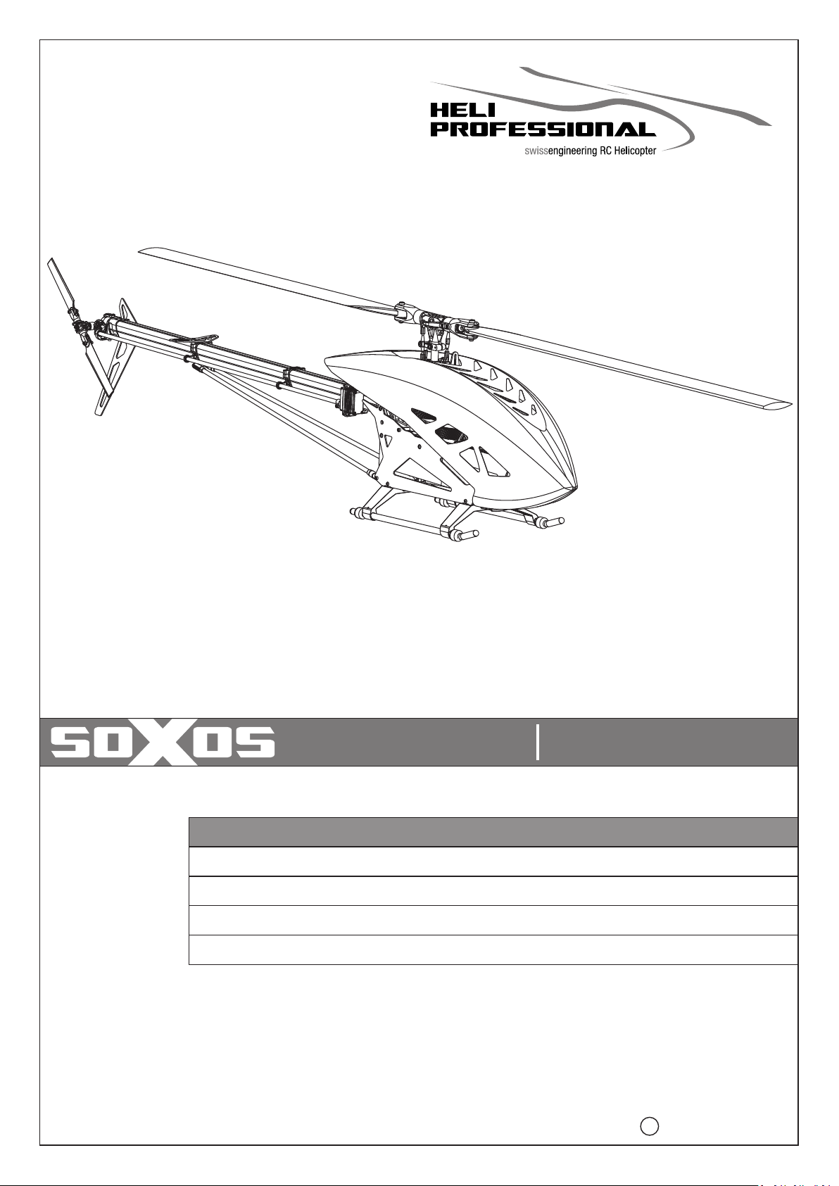
Bauanleitung und Handbuch V 1.0
STRIKE 7.1
INHALT/CONTENT
Technische Daten & Sicherheitshinweise/Specifications & Safety Instructions
Benötigtes Werkzeug & Allgemeine Hinweise/Required Tools & General Information
Bauanleitung und Handbuch/Assembly Instructions and Manual
Explosionszeichnung/Exploded view
Assembly Instruction and Manual V 1.0
Heli Professional 2021C
Page 2
SEHR GEEHRTER KUNDE
BESTEN DANK, DASS SIE SICH FÜR DEN SOXOS STRIKE 7.1 ENTSCHIEDEN HABEN.
Bevor Sie mit dem Zusammenbau oder der Inbetriebnahme beginnen,
lesen Sie diese Anleitung bitte sorgfältig durch!
DEAR CUSTOMER,
THANK YOU FOR CHOOSING THE SOXOS STRIKE 7.1 MODEL HELICOPTER.
Before beginning with the assembly or operating the helicopter,
please read this manual thoroughly!
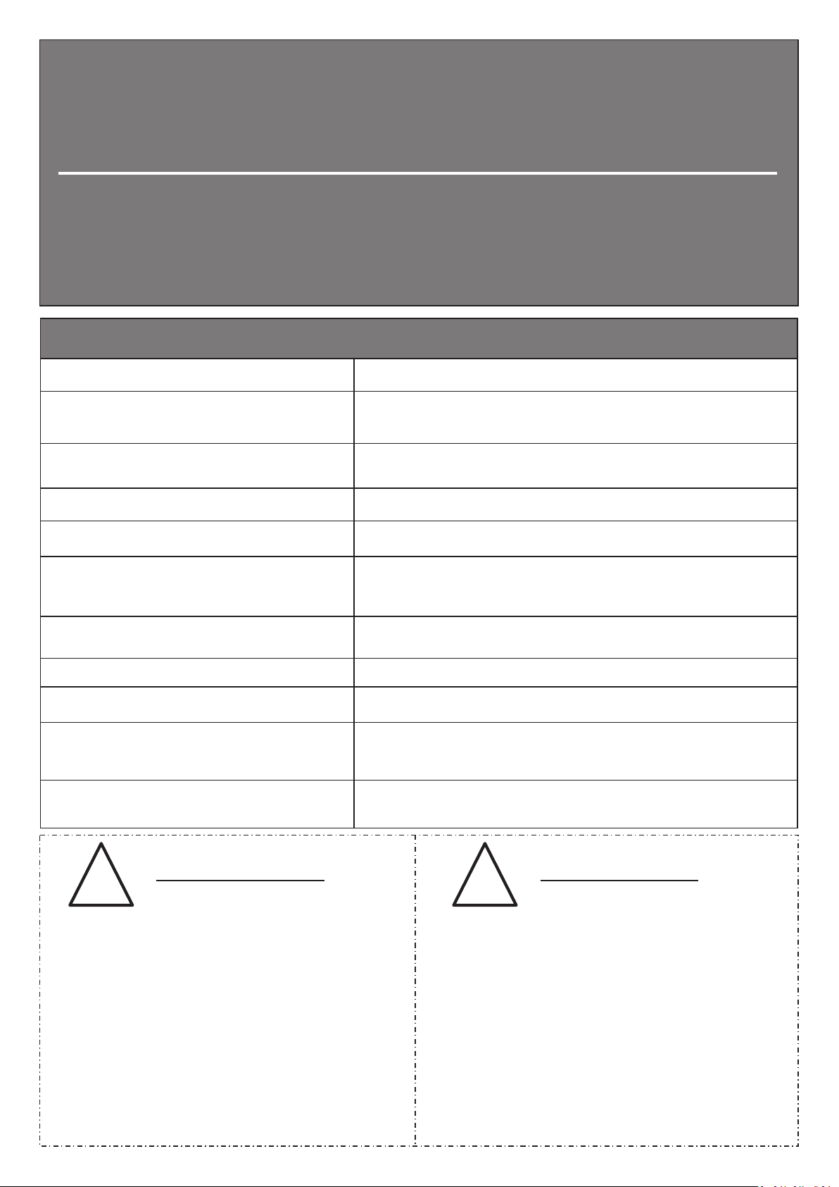
Technische Daten/Specifications
Hauptrotordurchmesser/Main Rotor Diameter: ca. 1570mm (mit 690mm lätter / with 690mm Blades)B
Gewicht (ohne Komponenten und Blätter):
Weight (without components and blades):
Gewicht 12S Setup (ohne Antriebsakku):
Weight 12S Setup (without batteries):
Länge/Length:
Höhe/Height:
Übersetzung Hauptrotor:
Gear ratio main rotor:
Übersetzung Heckrotor:
Gear ratio tail rotor:
Rotorblätter/Main blades:
Heckrotorblätter/Tail blades:
Maximale Grösse des Motors: Ø 63mm, Höhe 64mm, Motorwellenlänge von 20 - 56mm
Maximum size of the motor:
Maximale Abmessung des Antriebs-Akkus:
Maximum dimension of the battery:
ca. 2180g
ca. 3690g
ca. 1380mm
ca. 340mm
Getriebe Übersetzungen: Ritzel sind kompatibel für 6mm und 8mm Motorwellen
1:7.94 1:10.06
1:5.05
685mm - 710mm
105mm
Ø 63mm, height 64mm, motor shaft length from 20 - 56mm
Breite 62mm, Höhe 68mm, Länge 350mm
Width 62mm, Height 68mm, Length 350mm
Gear Options: Pinions are suitable for 6mm and 8mm motorshafts
15 Zähne/Ratio: 10.06
16 Zähne/Ratio: 9.43
17 Zähne/Ratio: 8.87
18 Zähne/Ratio: 8.38
19 Zähne/Ratio: 7.94
Sicherheitshinweise: Safety Instructions:
! !
Ein Modellhubschrauber ist kein Spielzeug, sondern ein
sehr leistungsfähiges Flugmodell, das bei unsachgemässer
Bedienung und Wartung grossen Schaden an Mensch und
Material verursachen kann. Kinder und Jugendliche sollten
einen Modellhubschrauber nur unter Aufsicht eines sachkundigen Erwachsenen bedienen. Heli Professional kann
für Haftungs- und Nachfolgeschäden von und mit Erzeugnissen aus dem Lieferprogramm nicht aufkommen und
lehnt deshalb jegliche Haftung ab, da ein ordnungsgemäßer
Betrieb oder Einsatz unsererseits nicht überwacht werden
kann. Zudem bitten wir Sie, sich an die Bedienungsanleitung
zu halten und nur Originalersatzteile von Heli Professional
zu verwenden.
A model helicopter is a very powerful flying device and not a
toy. Disregarding our instructions, inappropriate use, and
insufficient maintenance by persons lacking necessary
competence may result in injuries for the user and can cause
damage to the surroundings and to the model. Children and
adolescents should operate a model helicopter only under
supervision of an experienced adult. Heli Professional will not
accept responsibility for any damage caused by their products
and rejects any liability as we are not in a position to supervise
proper operation, handling, and maintenance by the user.
Furthermore, we ask you to follow our operating and
assembly instructions carefully and to use only original Heli
Professional parts.
Page 3
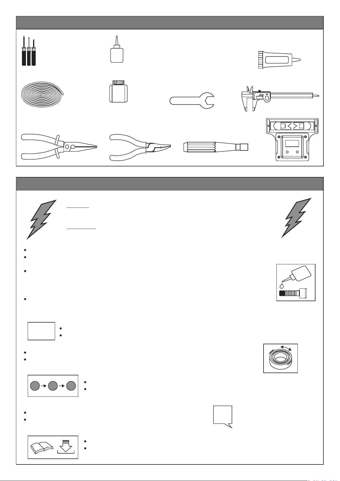
Benötigtes Werkzeug/Required Tools
Innensechskantschlüssel
Hexagon Socket Wrenches
SW 1.5/2/2.5/3
Schnur ca. 2m
String
Kombizange
Slip Joint Pliers
Allgemeine Hinweise/General Information
Schraubensicherungslack, mittelfest und fest
Threadlocker, medium and strong
Fett
Grease
Kugelkopfzange
Ball Link Pliers
Gabelschlüssel 5.5mm
Flat Wrench
Kugelkopfeindreher
Ball Link Driver
Sekundenkleber
CA (Cyanoacrylic Instant Adhesive)
Messschieber
Caliper
Digi-Pitch
WICHTIG:
IMPORTANT:
Es sind keine elektronischen Bauteile, wie z.B. Servos, etc. im Lieferumfang enthalten.
The kit does not include any electronic components such as servos, etc.
Grundsätzlich muss jede Schraube entfettet und mit Sicherungslack eingeklebt werden. Auch bereits
vormontierte Teile müssen diesbezüglich kontrolliert werden. Das rechts abgebildete Symbol soll Sie
während des Zusammenbaus daran erinnern.
Kugellager werden NICHT eingeklebt, ausser es wird darauf hingewiesen.
In general, every screw must be cleaned and secured with threadlocker. Also, check preassembled parts
regarding this. The symbol on the right-hand side is supposed to remind you while going through the
assembly process. Ball bearings must NOT be secured with threadlocker except where noted.
1:1
Achten Sie auf die Freigängigkeit aller verbauten Kugellager und Drucklager.
Check all ball bearings and thrust bearings for ease of movement.
Die in den Bauabschnitten mit diesem Symbol abgebildeten Schrauben, etc. sind in Originalgrösse dargestellt.
The screws and all other parts depicted with this symbol in the assembly steps are actual-size drawings.
Bevor Sie mit dem Zusammenbau oder der Inbetriebnahme beginnen,
lesen Sie diese Anleitung bitte sorgfältig durch!
Before beginning with the assembly or operating the helicopter,
please read this manual thoroughly!
A
Wiederholen Sie den Montageschritt so oft wie angegeben (hier: zwei Mal).
Repeat the assembly step as often as specified (here: twice).
B
C
Montieren Sie die Bauteile in der angegebenen Reihenfolge.
Assemble the parts in the specified order.
Handbücher und Bauanleitungen für Tuningteile sind direkt von der Webseite zu beziehen.
Manuals and assembly instructions for tuning parts are to be downloaded directly from the
website. www.soxos-heli.com
2x
Page 4
1
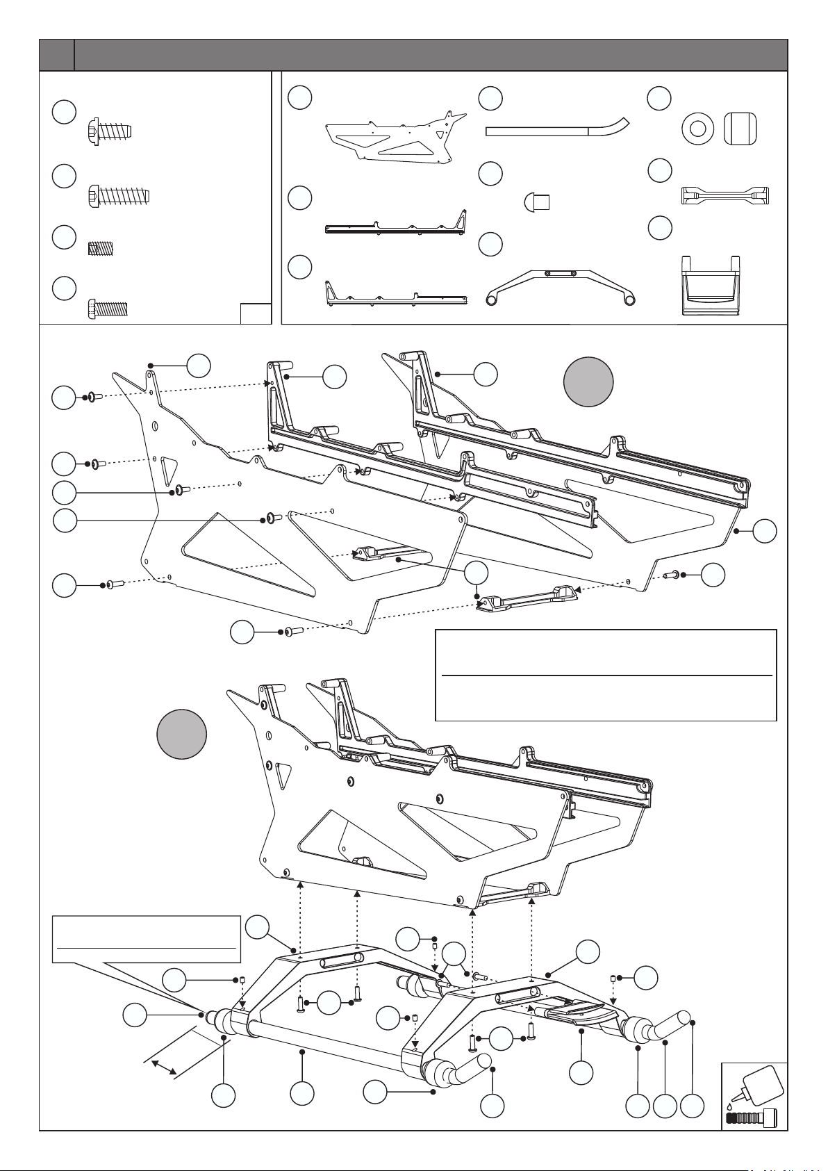
Normteile/Standard Parts
9
8
92
354
3x7.5
3x12
M3x6
M3x8
Linsenkopf Treibschraube
Flanged Round Head Self
Tapping Screw
Treibschraube
Self Tapping Screw
Gewindestift
Set Screw
Rundkopfschraube
Round Head Screw
9
9
1626
8x
2x
4x
8x
1:1
Carbon Seitenplatte
1626
Side Plate Carbon
Akkuschiene rechts
275
Battery Rail Plate right
Akkuschiene links
276
Battery Rail Plate left
275
2x
436
356
1x
1624
1x
Kufenrohr
Skid Pipe
Endkappe Kufenrohr
Skid Pipe Cap
Landegestell Weiss
Landing Skid White
2x
4x
2x
Kufengummi
464
Skid Rubber
Kufenhalterung
1664
Landing Skid Holder
Haubenhalterung
1625
Canopy Support
landing skid
4x
2x
1x
276
A
9
9
354
B
354
1626
1664
Die Kufenrohre müssen vor dem endgültigen Festziehen
plan und ohne Spannungen im Landegestell aufliegen.
Auf einer ebenen Unterlage überprüfen und ggf. justieren!
The landing skid pipes should be checked to make sure they are
level and not warped in the landing skids before finally tightening
them. Check on a flat surface and adjust if necessary!
354
Endkappe Kufenrohr mit Sekundenkleber einkleben!
Use CA to secure the Skid Pipe Cap!
92
356
c
a. 35 mm
464
1624
436
354
464
92
92
8
1624
92
354
1625
356
464
436
356
Page 5
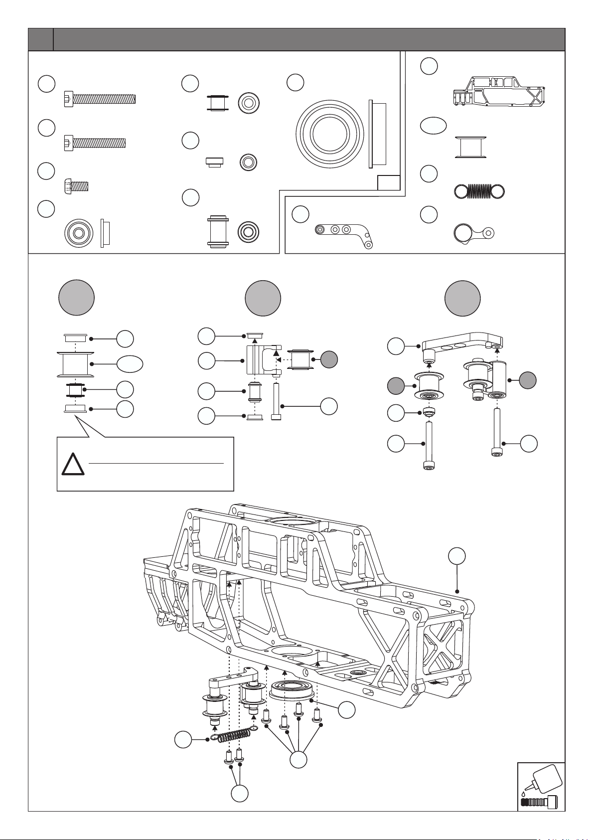
2
Normteile/Standard Parts
M3x22
M3x18
M3x6
3x8x3
A
Schraube
Hex Socket Screw
Schraube
Hex Socket Screw
Rundkopfschraube
Round Head Screw
Flanschlager
Flanged Bearing
1705
1680-01
142
105
155
1705
2x
1766
2x
1x
6x
6x
1706
1741
1738
Distanzhülse
Distance Sleeve
Feder U-Scheibe
Spring Washer
Distanzhülse
Distance Sleeve
2x
1x
1x
328
1777
12x24x6
Flanschlager
Flanged Bearing
Adapter Platte
Adapter Plate
1x
1:1
1680-01
1742
1x
1744
B
1705
1777
1744
A
Rahmen
Main Frame
Heckriemenführung
Tail Belt Guide
Zugfeder
Extension Spring
Klemmhebel
Gripping Lever
C
1x
2x
1x
1x
1706
1705
Alle Kugellager in der Baugruppe A
mit Sicherungslack einkleben!
Glue all ball bearings in the assembly
!
A with strong threadlocker!
1738
1705
105
A
1741
142
B
142
1766
1742
328
155
155
Page 6
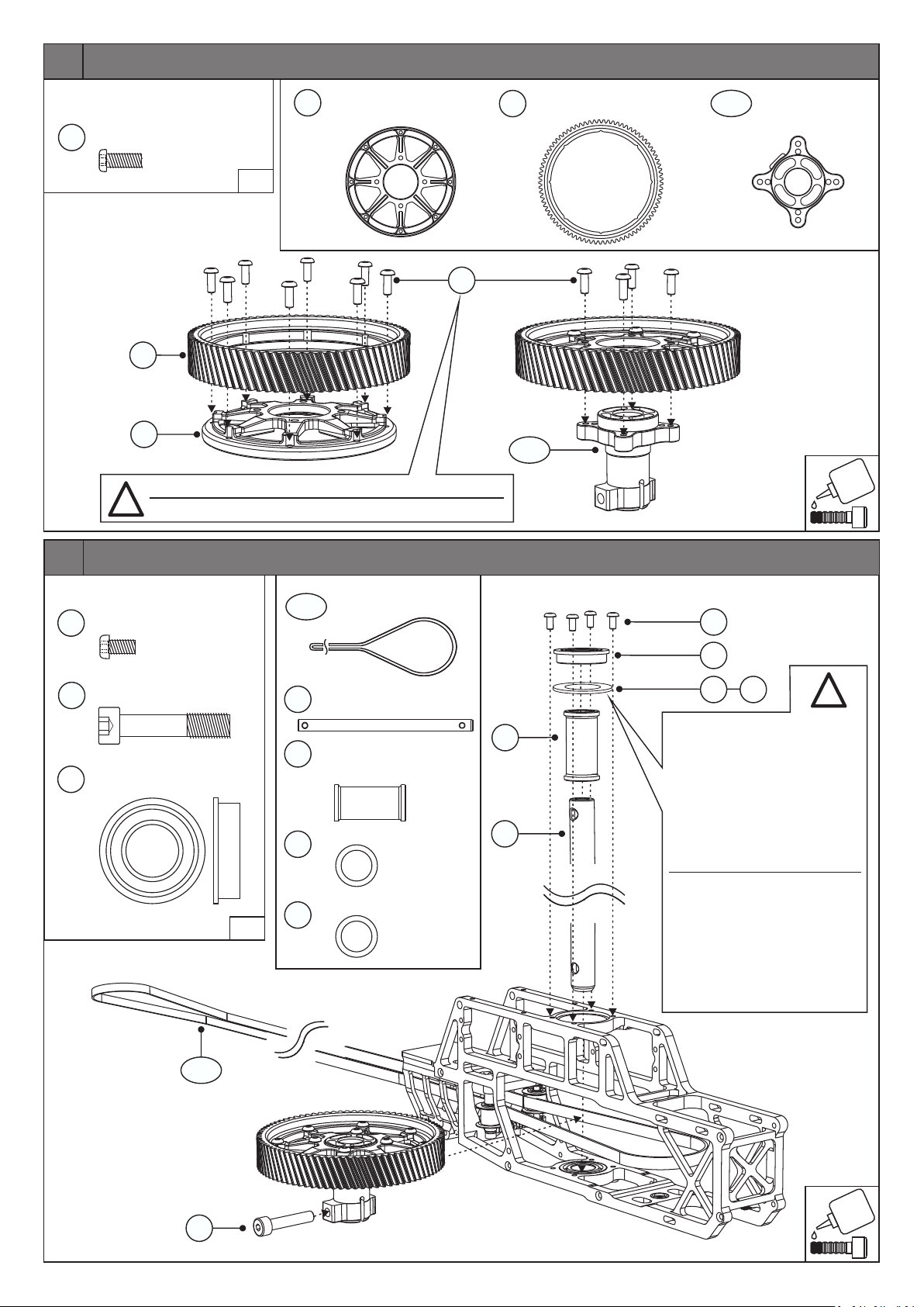
3
Normteile/Standard Parts
M3x8
354
Rundkopfschraube
Round Head Screw
1643
1641
Schrauben erst leicht eindrehen, danach gleichmässig anziehen!
!
First lightly seat the screws, then tighten them evenly!
12x
1:1
Hauptzahnrad Nabe
1641
Main Drive Hub
1x
354
Hauptzahnrad 81Z
1643
Main Drive Gear 81T
1719-02
1x
1719-02
Flanschmuffe
Flanged Sleeve
1x
4
Normteile/Standard Parts
M3x6
M5x25
12x24x6
Rundkopfschraube
Round Head Screw
Spezialschraube
Special Screw
Flanschlager
Flanged Bearing
155
488
328
4x
1x
1x
1:1
1743-06
1740
1682
1592
1593
Heckriemen
Tail Drive Belt
Hauptrotorwelle
Main Shaft
Distanzhülse
Hauptrotorwelle
Distance Sleeve Main Shaft
12x18x0.1 Passscheiben
Distance Washer
12x18x0.2 Passscheiben
Distance Washer
1x
155
328
1x
1682
1x
1740
2x
2x
1592 1593
!
Schrauben 155 mit Flanschlager
328 erst nach komplettem
Zusammenbau der Getriebeeinheit gleichmässig anziehen.
Getriebeeinheit und Rotorwelle
dürfen kein axiales Spiel im
Rahmen haben. Benutzen Sie ggf.
zur Justierung die beiliegenden
Passscheiben zwischen 328 & 1682.
After assembly of the transmission
unit tighten screws 155 on the
flanged bearing 328. There must
be no axial movement of the
transmission assembly when
installed in the frame. Use the
enclosed shim washers between
328 & 1682 if necessary.
1743-06
488
Page 7
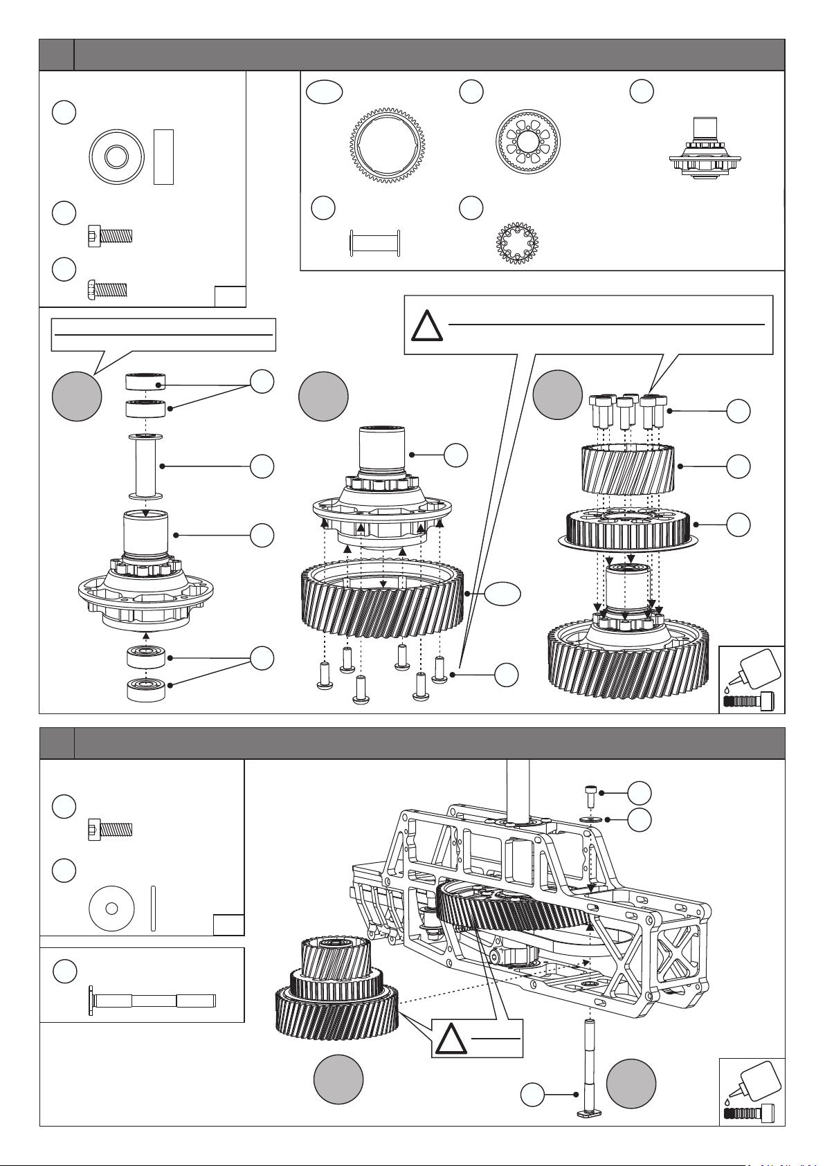
5
Normteile/Standard Parts
1720
303
354
5x14x5
M3x8
M3x8
Kugellager
Ball Bearing
Zylinderkopfschraube
Socket Head Screw
Rundkopfschraube
Round Head Screw
4x
8x
6x
1:1
Werksseitig bereits montiert und gesichert.
Factory assembled and secured.
A
1720
1746
1636-02
1746
B
Zahnrad 54Z
Drive Gear 54T
Distanzhülse
Distance Sleeve
1x
1x
Schrauben erst leicht eindrehen, danach gleichmässig anziehen!
!
First lightly seat the screws, then tighten them evenly!
Heckriemenrad 47Z
1733
Tail Drive Pully 47T
Zahnrad 29Z
1730
Drive Gear 29T
1x
1x
Autorotationsnabe
1729
Autorotation Hub
C
1729
1x
303
1730
6
Normteile/Standard Parts
M3x8
303
1752
Zylinderkopfschraube
Socket Head Screw
3x11.5x1
U-Scheibe
Washer
1729
1636-02
1720
1733
354
1x
1x
303
1752
Zwischenachse
1745
Axel intermediate Gear
1:1
1x
A
!
Einfetten
Grease
1745
B
Page 8
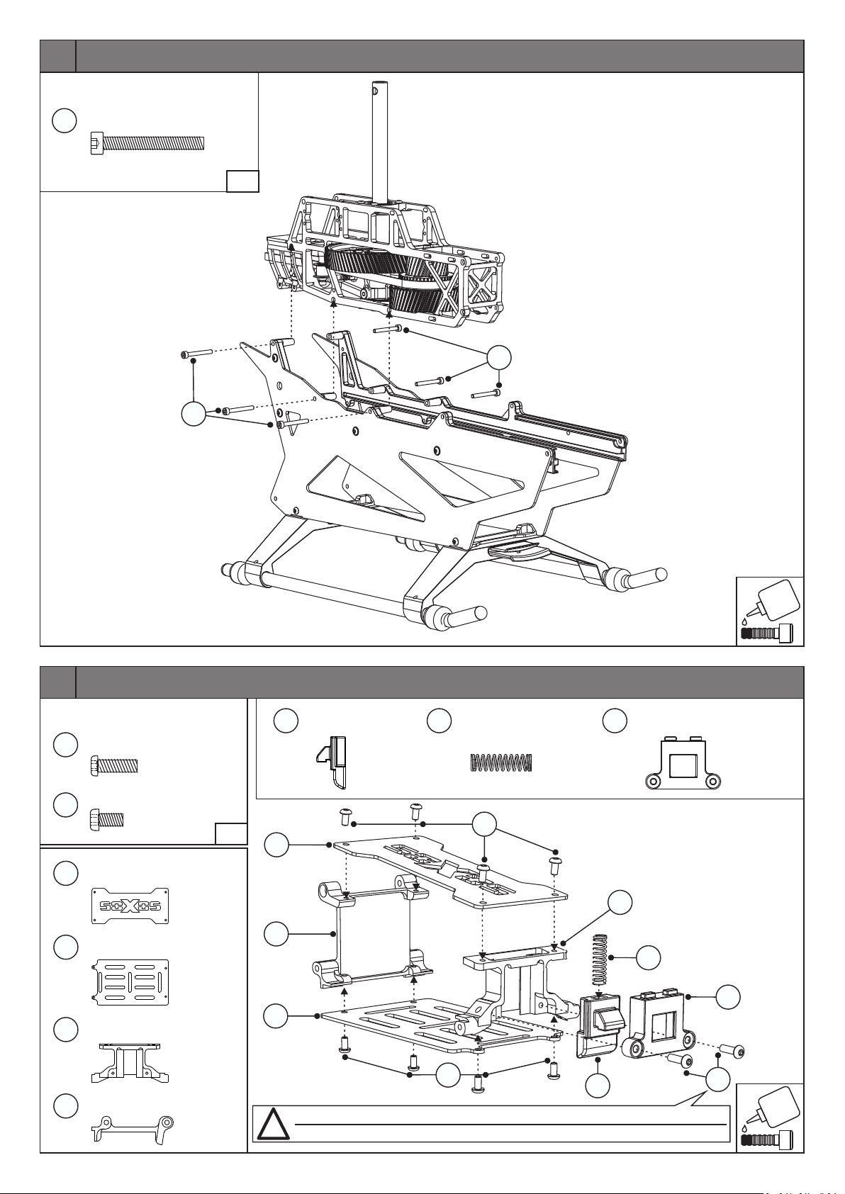
7
Normteile/Standard Parts
55
M3x25
Zylinderkopfschraube
Socket Head Screw
6x
1:1
55
55
8
Normteile/Standard Parts
M3x10
1684
M3x6
155
Vorbaudeckel
1551
Porch Plate Top
Vorbauboden
1552
Porch Plate Bottom
Bolzen Halterplatte
546
Bolt Box Plate
Halterung
547
Porch Holder
Rundkopfschraube
Round Head Screw
Rundkopfschraube
Round Head Screw
2x
8x
1:1
1x
1x
1x
1x
318
Verschluss
Latch
1x
350
Druckfeder
Pressure Spring
1x
319
Verschlussgehäuse
Bolt Box
155
1551
546
547
350
1552
155
318
Schraube 1684 nicht zu stark anziehen und auf Leichtgängigkeit des Verschlusses 318 achten!
!
Do not overtighten screw 1684 to keep smooth movement of latch 318!
1x
319
1684
Page 9
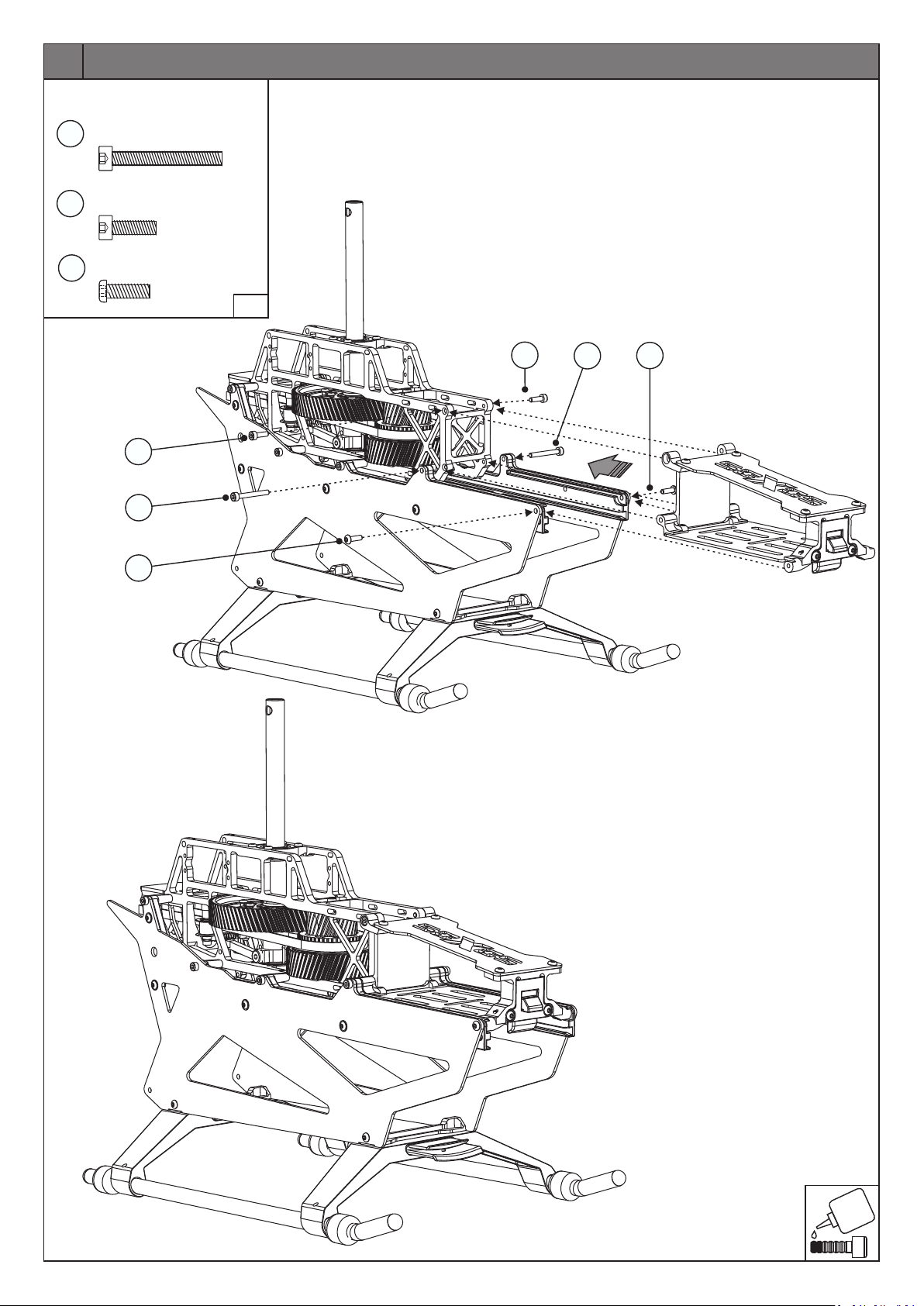
9
Normteile/Standard Parts
M3x25
55
Zylinderkopfschraube
Socket Head Screw
2x
71
1684
M3x10
Zylinderkopfschraube
Socket Head Screw
M3x10
Rundkopfschraube
Round Head Screw
71
55
1684
1:1
2x
2x
71
55
1684
Page 10
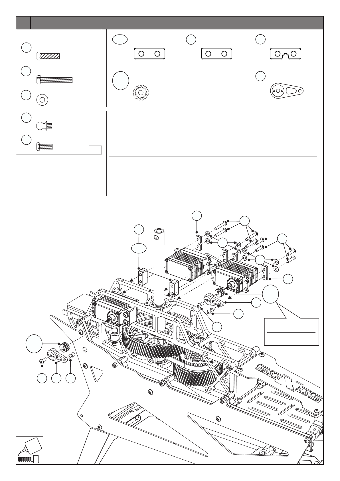
10
Normteile/Standard Parts
M3x12
M3x20
M3
M3x4.5
M3x8
Rundkopfschraube
Round Head Screw
Rundkopfschraube
Round Head Screw
U-Scheibe
Washer
Kugelkopf
Ball End Screw
Rundkopfschraube
Round Head Screw
1600
1601
11
145
354
4x
8x
137-01
1659
1663
12x
3x
Je nach verwendeten Servos müssen Sie die unterschiedliche Einbautiefe der Servos durch die
Servodistanz 7 mm
Servo Distance Block
Servo Einsatz 23Z,24Z,25Z,25Z/8
Insert Servo 23T,24T,25T,25T/8
-
4x
Servodistanz 9.5 mm
1665
Servo Distance Block
4x
Servoplättchen
41
Servo Mounting Plates
Servoarm
1797
Servo Horn
Verwendung des 7mm oder 9,5mm Servodistanzblocks ausgleichen. Für weitere Anpassungen
können Sie die dünneren Servo-Montageplatten verwenden. Wichtig: Verwenden Sie auf jeder
Seite die gleiche Anzahl an Servo-Montageplatten. Alle Teile auf Freigängigkeit prüfen. Die Servos
3x
dürfen sich nicht in der Mitte des Rahmens berühren. Die Schubstangen sollten so senkrecht wie
möglich zur Taumelscheibe sein.
1:1
Je nach Art des verbauten Servos können die Schrauben aus der Rahmeninnenseite herausragen.
Depending on the servos used, you must compensate the differing mounting depth of the servos by
using the 7mm or 9.5mm servo distance block. For more adjustment you can use the thinner servo
mounting plates. Important: Use the same amount of servo mounting plates on each side. Check all
the servo to swash links should be as close to vertical as possible.
Depending on the type of servo installed, the screws may protrude from the inside of the frame.
10x
3x
parts for ease of movement. The servos must not touch each other in the middle of the frame but
1659
-
1663
354
1797
145
OPTIONAL
1665
137-01
OPTIONAL
42
354
11
OPTIONAL
145
1601
1600
11
1659
-
1663
1797
Den passenden Einsatz
zum Servo verwenden
Use the correct
insert for the servo
42
Page 11
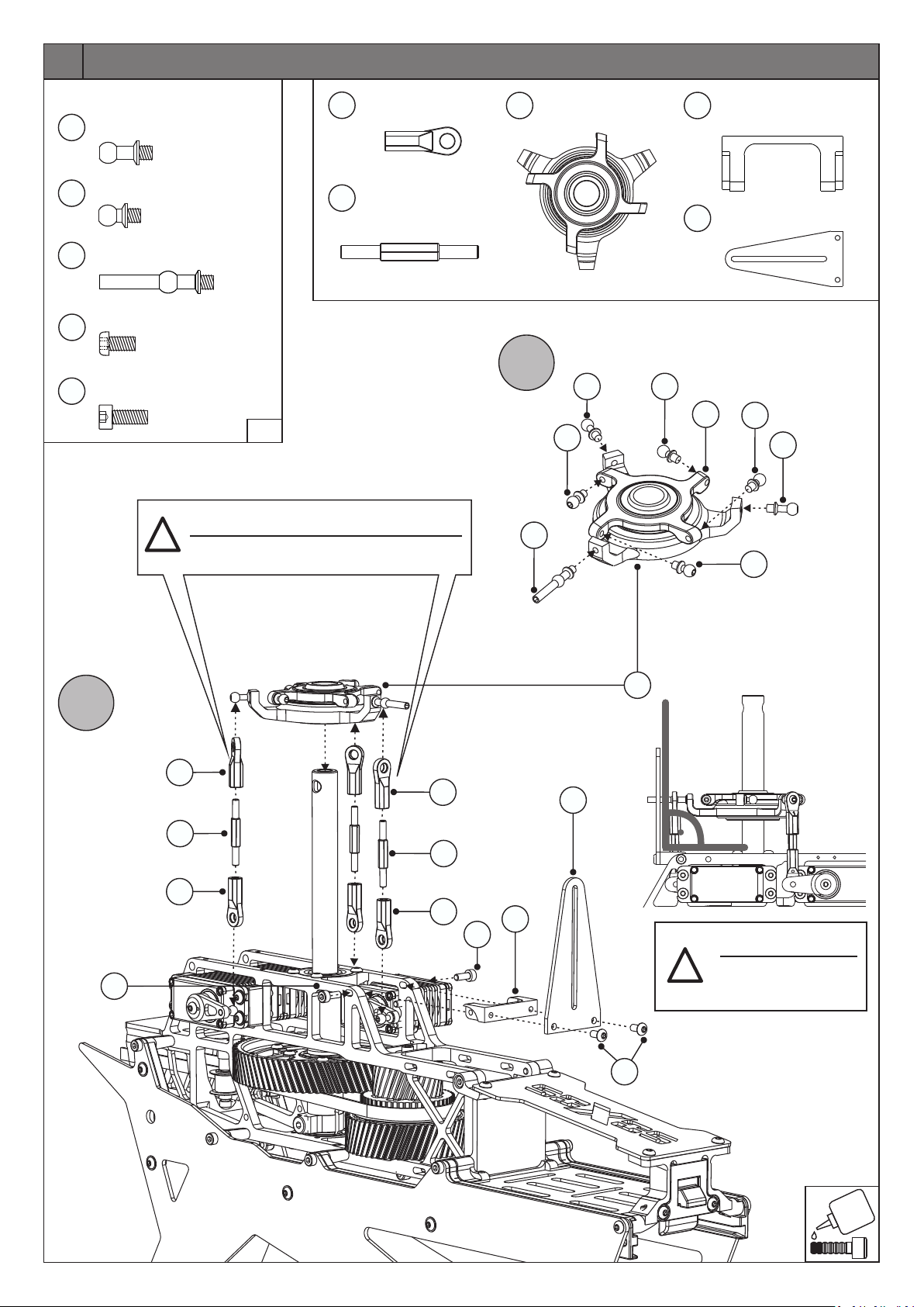
11
Normteile/Standard Parts
M3x7
M3x4.5
M3x7
M3x6
M3x8
Kugelkopf
Ball End Screw
Kugelkopf
Ball End Screw
Kugelkopf lang
Ball End Screw long
Rundkopfschraube
Round Head Screw
Zylinderkopfschraube
Socket Head Screw
309
145
549
155
303
!
2x
4x
1x
2x
2x
359
1798
Kugelpfanne
Ball Link
Schubstange
Control Rod
1:1
Schrauben Sie die Kugelpfannen 359 so weit wie
möglich auf der Schubstange 1798 zusammen.
Screw ball links 359 together as far as possible
on the control rod 1798!
6x
3x
1789
Taumelscheibe
Swashplate
1x
Taumelscheibenführungs-
548
Halter
Swashplate Guide Holder
Taumelscheibenführung
1799
Swashplate Guide
1x
1x
A
309
145
549
145
1698
145
309
145
B
303
359
1798
359
359
1798
359
303
548
1799
155
1789
Auf Rechtwinkligkeit der
TS-Führung 1799 achten.
Pay attention to the
!
perpendicularity of the
Swashplate Guide 1799.
Page 12
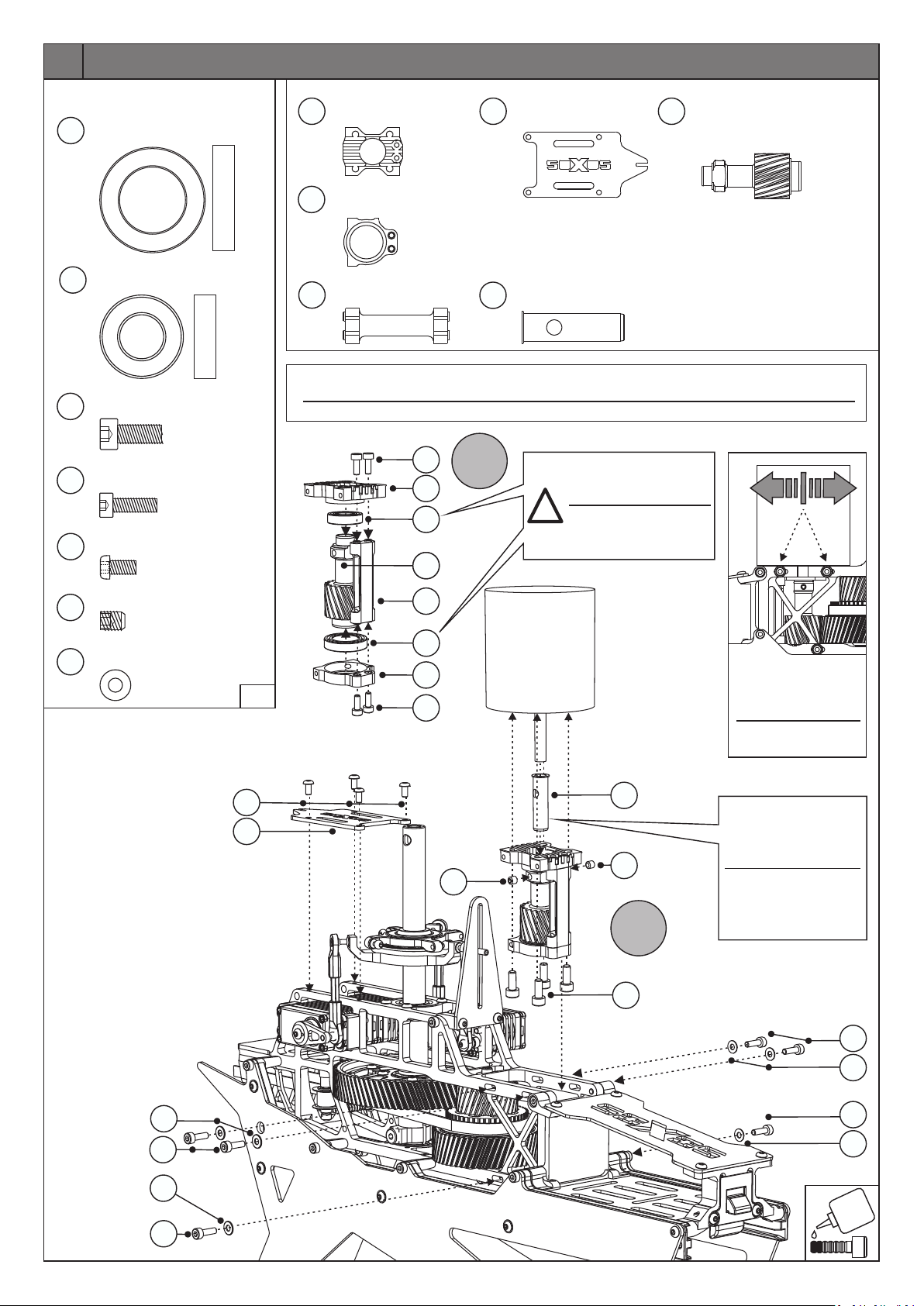
12
Normteile/Standard Parts
1800
417
528
71
155
15x24x5
M4x10
M3x10
Kugellager
Ball Bearing
10x19x5
Kugellager
Ball Bearing
Zylinderkopfschraube
Socket Head Screw
Zylinderkopfschraube
Socket Head Screw
M3x6
Rundkopfschraube
Round Head Screw
10x
Motorplatte
1754
1x
1x
Motor Plate
Motor Gegenplatte
1755
Motor Counterplate
Distanz Platte
1756
Distance Plate
1x
1x
1x
Empfängerplatte
1550
Receiver Plate
b
Adapterhülse 6mm
1801
Adapter Sleeve
1x
(Ritzel sind erhältlich für 6mm und 8mm Motorwellen)
(Pinions available for 6mm and 8mm motorshafts)
1x
16z/8mm/6mm Ritzel
1758
Für Motoren von 520-560KV/12S
16T/8mm/6mm Pinion
for motors from 520-560KV/12S
Getriebe Übersetzungen:
15 Zähne/Ratio: 10.06
16 Zähne/Ratio: 9.43
17 Zähne/Ratio: 8.87
18 Zähne/Ratio: 8.38
19 Zähne/Ratio: 7.94
Gear Options:
Beim Eindrehen der Motorschraube darauf achten, dass die Wicklungen des Motors nicht verletzt
4x
werden. Ggf. andere Schrauben verwenden.
Make sure not to damage the windings with the motor screws. Use different screws if necessary.
71
1754
A
417
4x
1761
1758
Kugellager 417 & 1800
mit Sicherungslack
einkleben
!
Glue in ball bearings
417 & 1800 with strong
threadlocker
1820
11
M4x5
M3
Gewindestift
Set Screw
U-Scheibe
Washer
1:1
155
1550
b
2x
6x
1756
1800
1755
71
OPTIONAL
Zahnflankenspiel
anhand der Langlöcher
einstellen.
Adjust backlash with
the slotted holes.
1801
Adapter Hülse für
6mm Motorwelle. Bei
Montage auf das Loch
1820
1820
für Gewindestift achten.
Adapter sleeve for
6mm motor shaft.
When mounting, align
B
to the hole for set screw.
528
71
11
71
11
71
11
71
11
Page 13
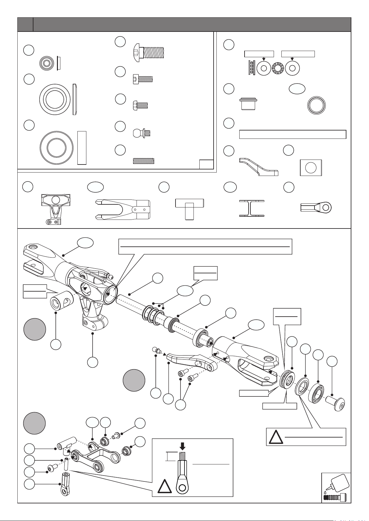
13
Normteile/Standard Parts
Flanschlager
3x7x3
54
420
417
1810
Flanged Bearing
10.2x17.5x1.5
10x19x5
Kugellager
Ball Bearing
Zentralstück
Main Hub
Adapterscheibe
Shim Washer
1x
542-02
505
4x
303
2x
155
4x
145
1602
Blatthalter
Blade Holder
M6x14
M3x8
M3x6
M3x4.5
Gewindestift
Set Screw M3x12
Rundkopfschraube
Round Head Screw
Zylinderkopfschraube
Socket Head Screw
Rundkopfschraube
Round Head Screw
Kugelkopf
Ball End Screw
2x
1817
2x
4x
2x
2x
1x
1:1
Kugelpfannenhalter
Ball Link Holder
1x
10x18x5.5
416
Dämpferhülse
1811
Damper Sleeve
Blattlagerwelle
407b
Spindle Shaft
Mischhebelarm
408c
Mixing Lever Arm
Mitnehmer Arm
1556b
Mixing Lever
Drucklager
Thrust Bearing
large ID (IN) small ID (OUT)
IN OUT
2x
2x
1812
1x
359
Dämpfer 70°
1813-70
Damper 70°
Blattlagerwellenführung
Spindle Shaft Support
Kugelkopf
Ball Link
2x
6x
1x
1x
1x
Einfetten
Grease
A
1812
542-02
1810
Ausgleichsgewicht einseitig montiert für den Ausgleich des TS-Mitnehmers.
Balance weight to compensate for one-sided swash driver.
Einfetten
1813-70
Grease
1811
417
542-02
large ID (IN)
Einfetten.
Grease.
OUT
small ID (OUT)
407b
B
145
408c
303
416
420
417
505
1817
1602
155
155
C
1556b
54
155
54
5 mm
!
Zuerst in Kugelkopf schrauben!
Thread screw
into plastic
Ball Link first!
Fase zeigt nach aussen.
!
Chamfer points outwards.
Page 14
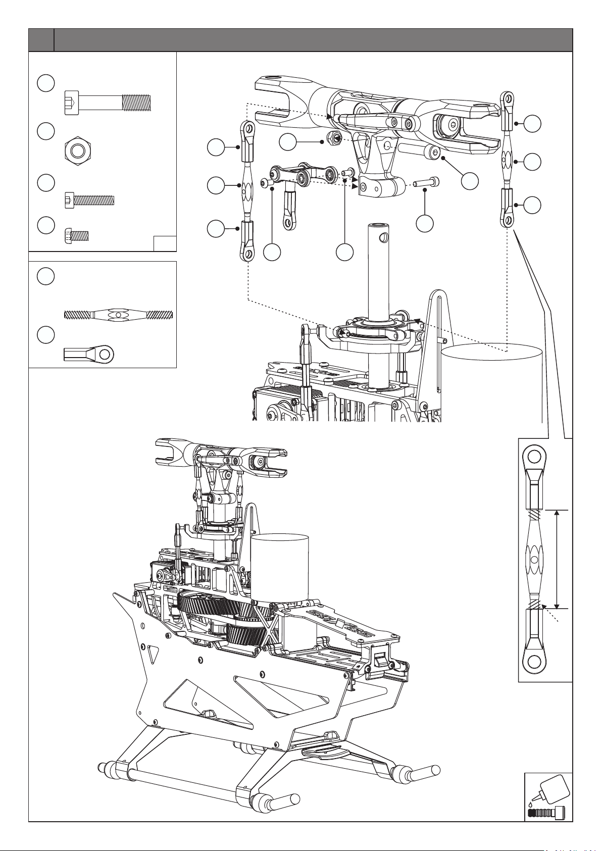
14
Normteile/Standard Parts
M5x25
488
Spezialschraube
Special Screw
1x
M5
427
M3x14
32
M3x6
155
Anlenkgestänge
1809
(Links-Rechts Gewinde)
Head Linkage Rod
(Left and Right thread)
Kugelpfanne
359
Ball Link
Stoppmutter
Lock Nut
Zylinderkopfschraube
Socket Head Screw
Rundkopfschraube
Round Head Screw
1x
1x
2x
1:1
2x
4x
359
1809
359
155
359
427
1558
488
359
32
155
OPTIONAL
OPTIONAL
34,5 mm
Links-Gewinde
Left thread
Page 15
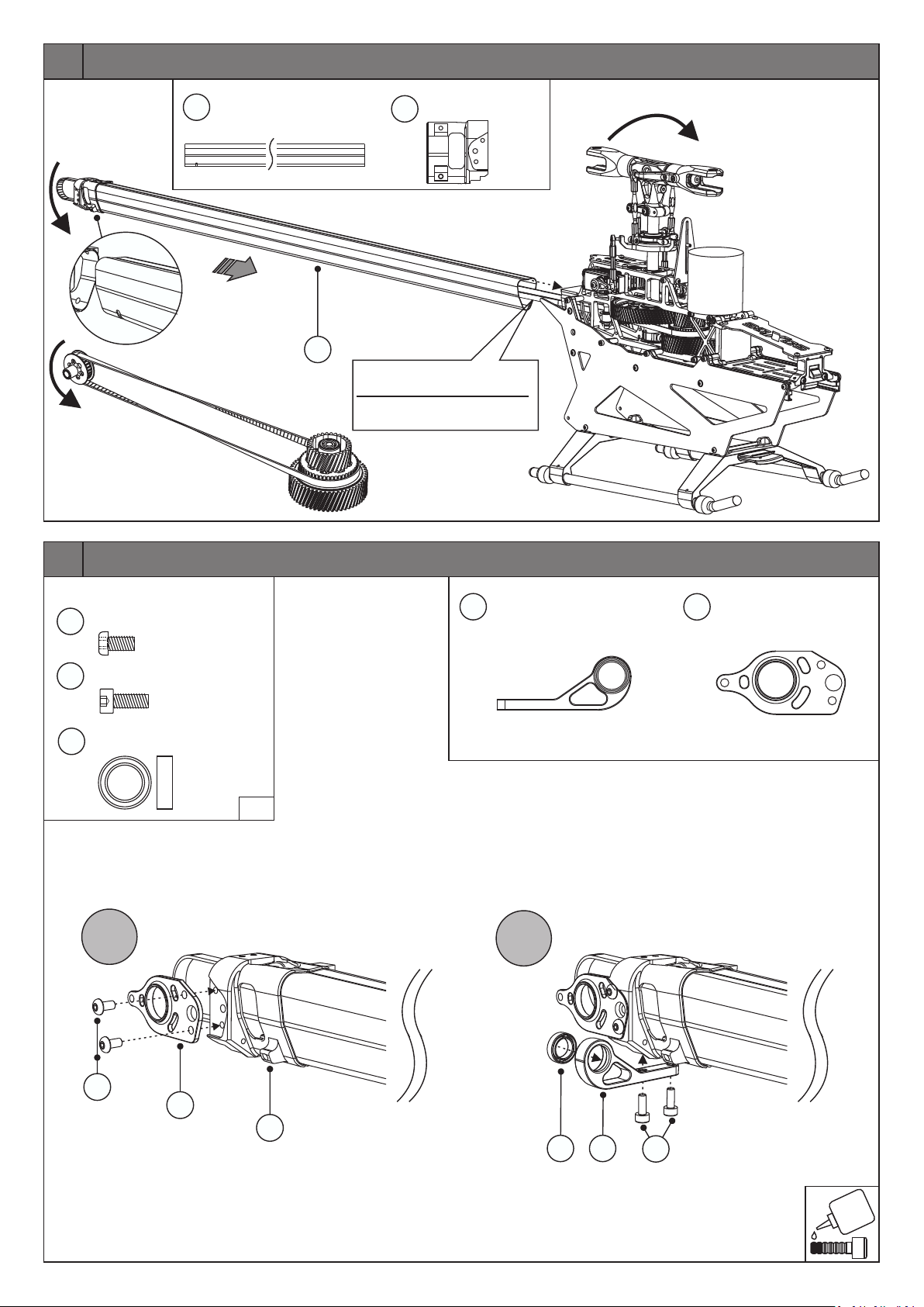
15
1764
Heckrohr 700
Tail Boom 700
1764
1x
Heckriemen mit Schnur durch
das Heckrohr ziehen.
Insert tail drive belt into tail
boom with a piece of string.
Heckrotorgehäuse
1765
Tail Rotor Housing
1x
OPTIONAL
16
Normteile/Standard Parts
M3x6
155
303
383
Rundkopfschraube
Socket Head Screw
M3x8
Zylinderkopfschraube
Socket Head Screw
8x12x3.5
Kugellager
Ball Bearing
A
2x
2x
1x
1:1
Drehstablagerung Heckgehäuse
1771
Torque Tube Support Tail
B
1x
Seitenplatte Heckgehäuse
1767
Tail Rotor Housing Side Plates
1x
155
1767
1765
383
1771
303
Page 16
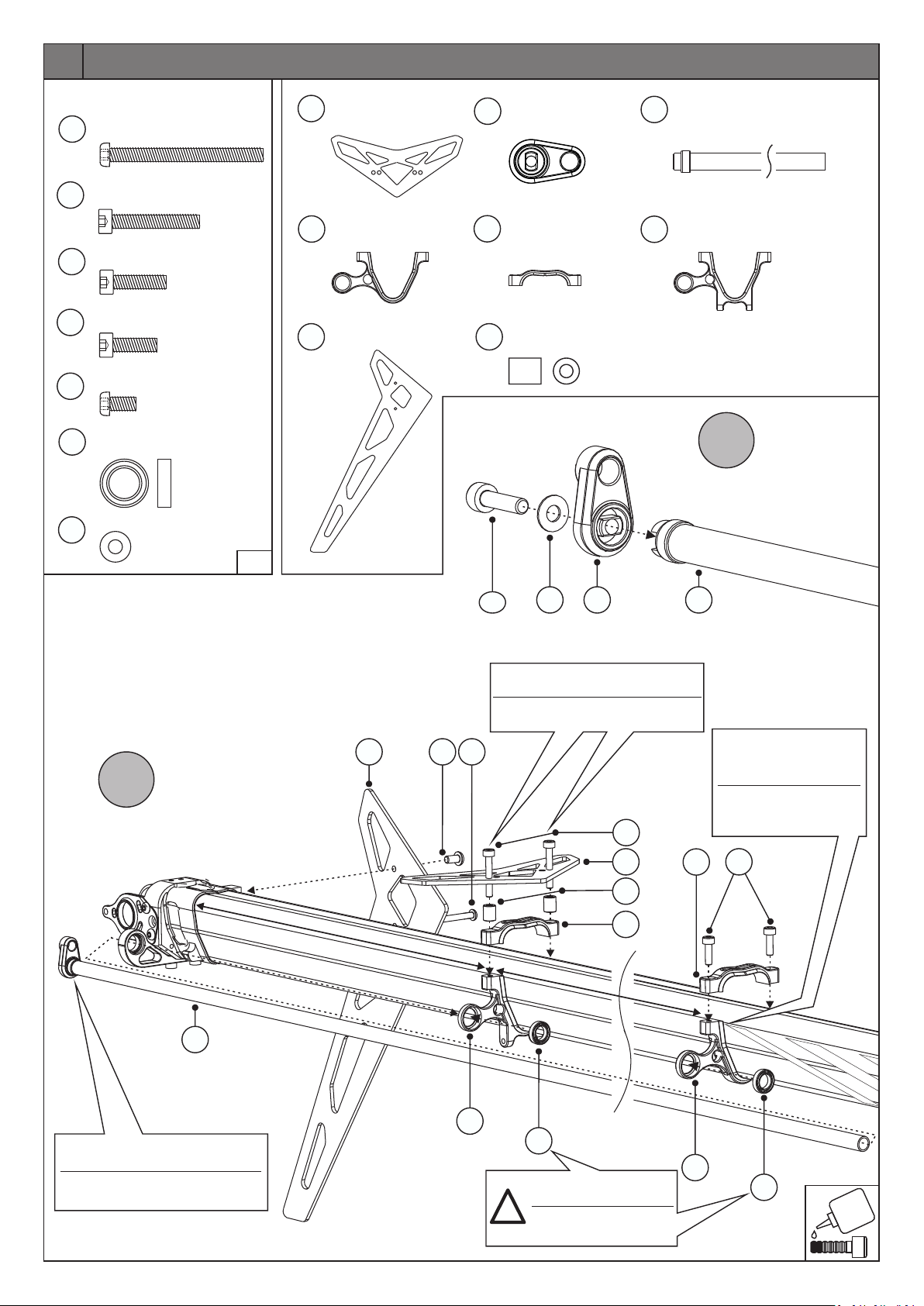
17
Normteile/Standard Parts
M3x35
1787
17
149
71
155
296
11
Rundkopfschraube
Round Head Screw
M3x20
Zylinderkopfschraube
Socket Head Screw
M3x12
Zylinderkopfschraube
Socket Head Screw
M3x10
Zylinderkopfschraube
Socket Head Screw
M3x6
Rundkopfschraube
Round Head Screw
7x11x3
Kugellager
Ball Bearing
M3
U-Scheibe
Washer
Carbon Höhenleitwerk
1668
1x
2x
1x
2x
1x
2x
Carbon Stabilizer Fin
Drehstablagerung
1780
Torque Tube Support
Carbon Seitenleitwerk
1667
Carbon Vertical Fin
1x
1x
1x
Steuerhebel
266
Tail Lever
Halterklemme, oben
1781
Upper Holder Clamp
Höhenleitwerksdistanz
448
Stabilizer Fin Spacer
1x
2x
2x
Drehstab
388a
Torque Tube
Höhenleitwerkhalterklemme unten
1782
Lower Stabilizer Fin Clamp
1x
1x
A
1x
B
1:1
c
a. 240 mm
1667
155
266
149
Diese Schrauben erst nach
Montage der Heckstreben anziehen.
Clamp with these screws after
having installed the tail brace tubes.
1787
11
1668
448
1781
ca. 230 mm
17
388a
Drehstablagerung
am Ende der Heckrohr
Design-Linien montieren.
Torque Tube Support
mount at the end of the
tail boom design lines.
1781
71
388a
Drehstab ganz nach vorne zum
Kugellager 383 einschieben.
Slide the torque tube completely in,
to the bearing 383.
1782
296
Kugellager 296 mit
Sicherungslack einkleben
!
Glue in ball bearings 296
with strong threadlocker
1780
296
Page 17
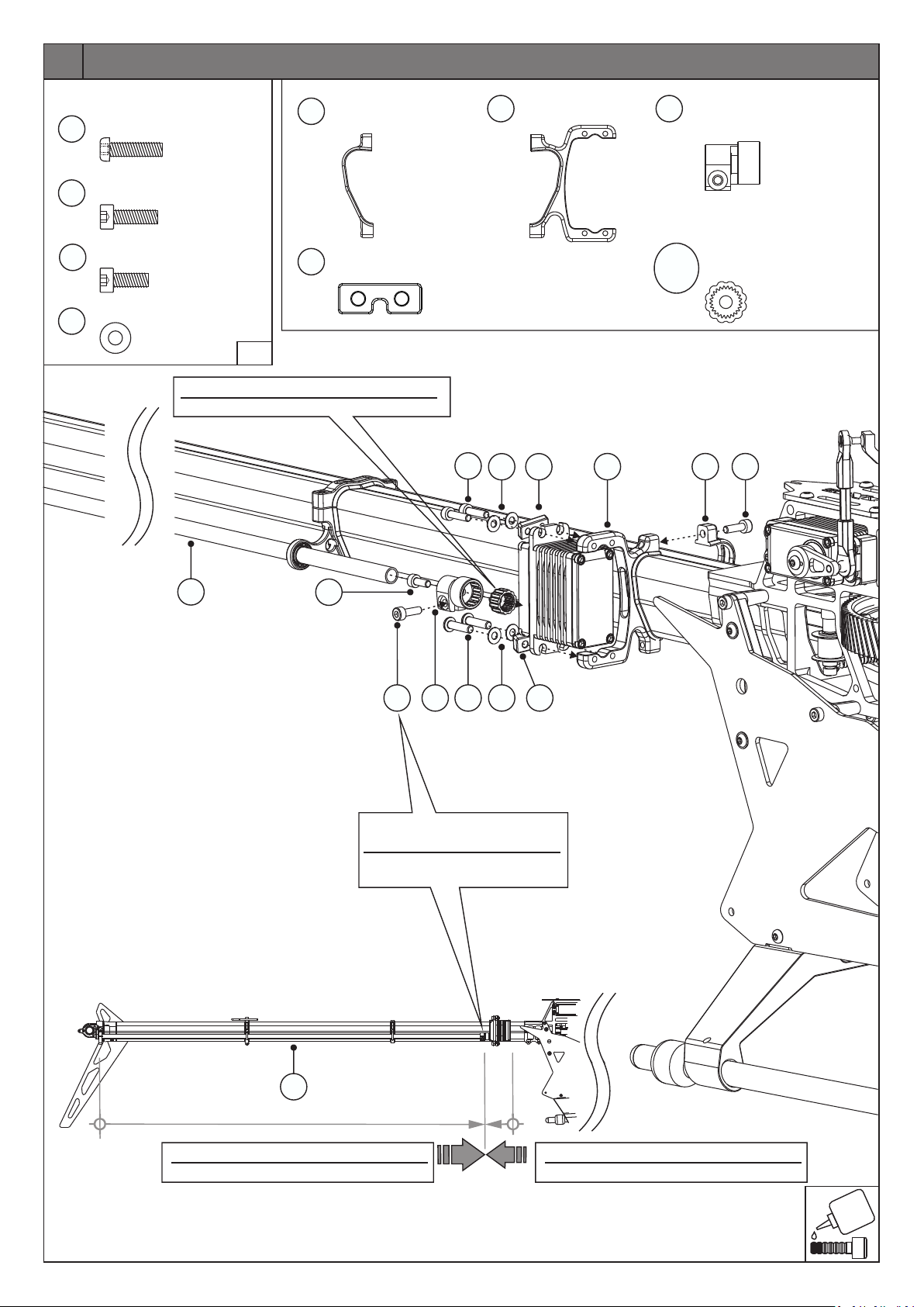
18
Normteile/Standard Parts
M3x12
1600
71
303
11
Rundkopfschraube
Round Head Screw
Zylinderkopfschraube
M3x10
Socket Head Screw
M3x8
Zylinderkopfschraube
Socket Head Screw
M3
U-Scheibe
Washer
Den passenden Einsatz zum Servo verwenden
Use the correct insert for the servo
4x
3x
1x
4x
1:1
Halterklemme, oben
1778
Upper Holder Clamp
Servoplättchen
41
Servo Mounting Plates
1x
2x
1600
1776
11
Heckservohalter
Tail Servo Holder
41
1776 1778
1x
1658
Drehstabhebel
Torque Tube Lever
Servo Einsatz 23Z,24Z,25Z,25Z/8
1659
Insert Servo 23T,24T,25T,25T/8
-
1663
1x
71
388
303
1658
1600
11
71
41
Erst beim Programmieren des
Heckservos endgültig anziehen.
Tighten fully after centring the tail
servo, apply threadlocker.
OPTIONAL
388a
Drehstab ganz nach vorne schieben.
Push the Torque Tube all the way to the front.
Servo ganz nach hinten schieben.
Push the servo all the way back.
Page 18
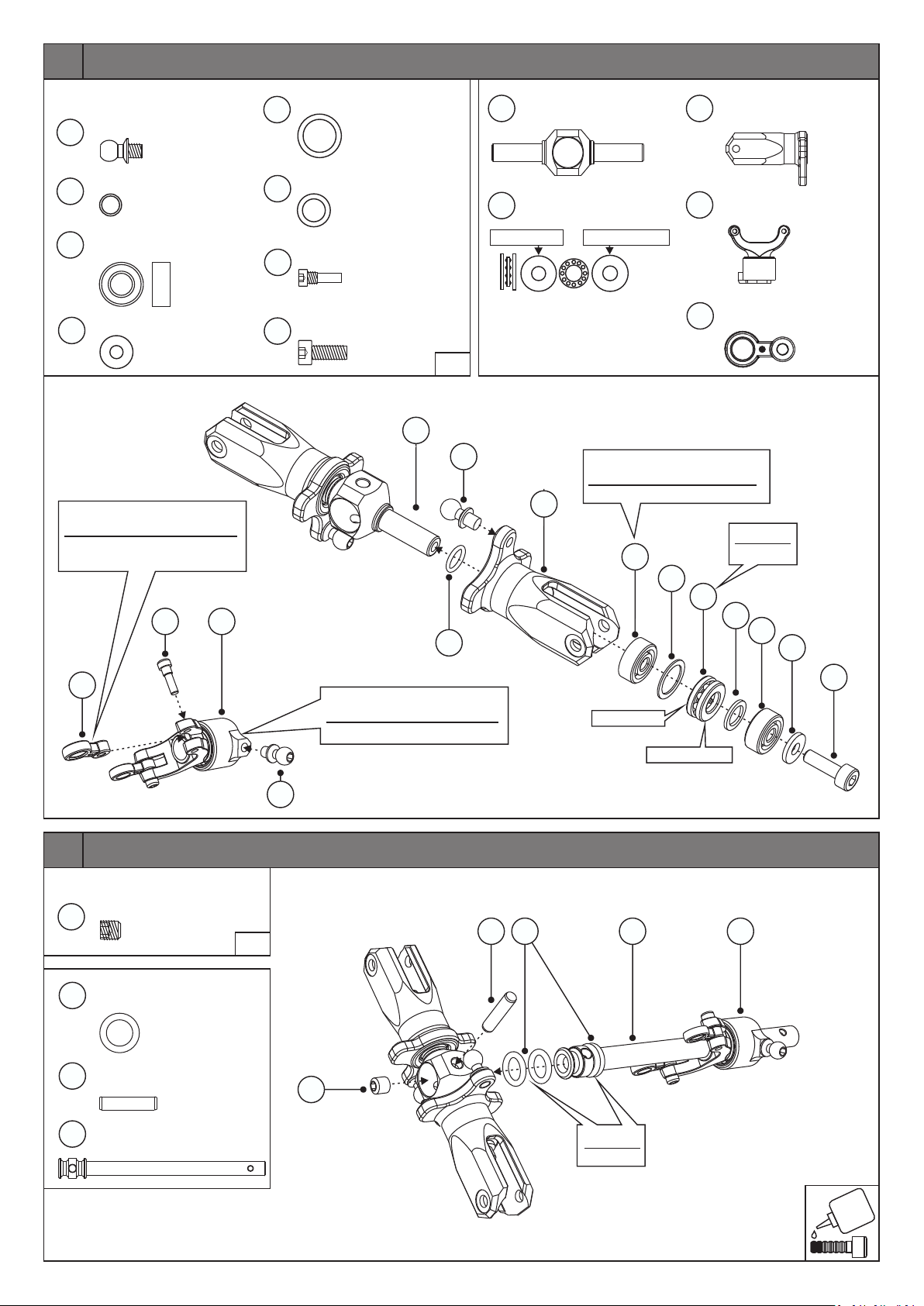
19
Normteile/Standard Parts
145
444
68
70
M3x4.5
5x1
5x10x4
3x7.5x1
Kugelbolzen
Ball-End Screw
O-Ring
Kugellager
Ball Bearing
Unterlegscheibe
Washer
Punkt auf 268 muss Richtung
Schraubenkopf 503 sein.
Raised dot on 268 must be in
direction screw head 503.
503
1773
7.5x9.9x0.4
69
3x
443
503
303
5.2x7.5x0.7
M2x5.5
M3x8
2x
4x
2x
Shim Washer
Passscheibe
Shim Washer
Zylinderkopfschraube
Socket Head Screw
Zylinderkopfschraube
Socket Head Screw
2xPassscheibe
1711
2x
151
Heckrotornabe
Tail Rotor Hub
5x10x4
large ID (IN) small ID (OUT)
2x
IN OUT
2x
Drucklager
Thrust Bearing
1x
2x
Blatthalter Heckrotor
1704
Blade Holder Tail Rotor
Hecksteuerbrücke
1773
1773
Tail Pitch Control
Hecksteuerbrückenarme
268
Tail Pitch Control Arms
2x
1x
2x
1:1
1711
145
1704
444
Kugellager werksseitig bereits
montiert.
Ball bearing already assembled.
Einfetten.
68
Grease.
69
151
443
68
70
268
20
Normteile/Standard Parts
M4x4
33
1714
1715
1768
Dämpfergummi
Damper Rubber
3x13 Bolzen
Bolt
Heckrotorwelle
Tail Rotor Shaft
Gewindestift
Set Screw
1x
1:1
4x
1x
1x
145
Werksseitig bereits montiert
und gesichert.
Factory assembled and secured.
33
1714
large ID (IN)
Einfetten.
Grease.
303
OUT
small ID (OUT)
177317681715
Page 19
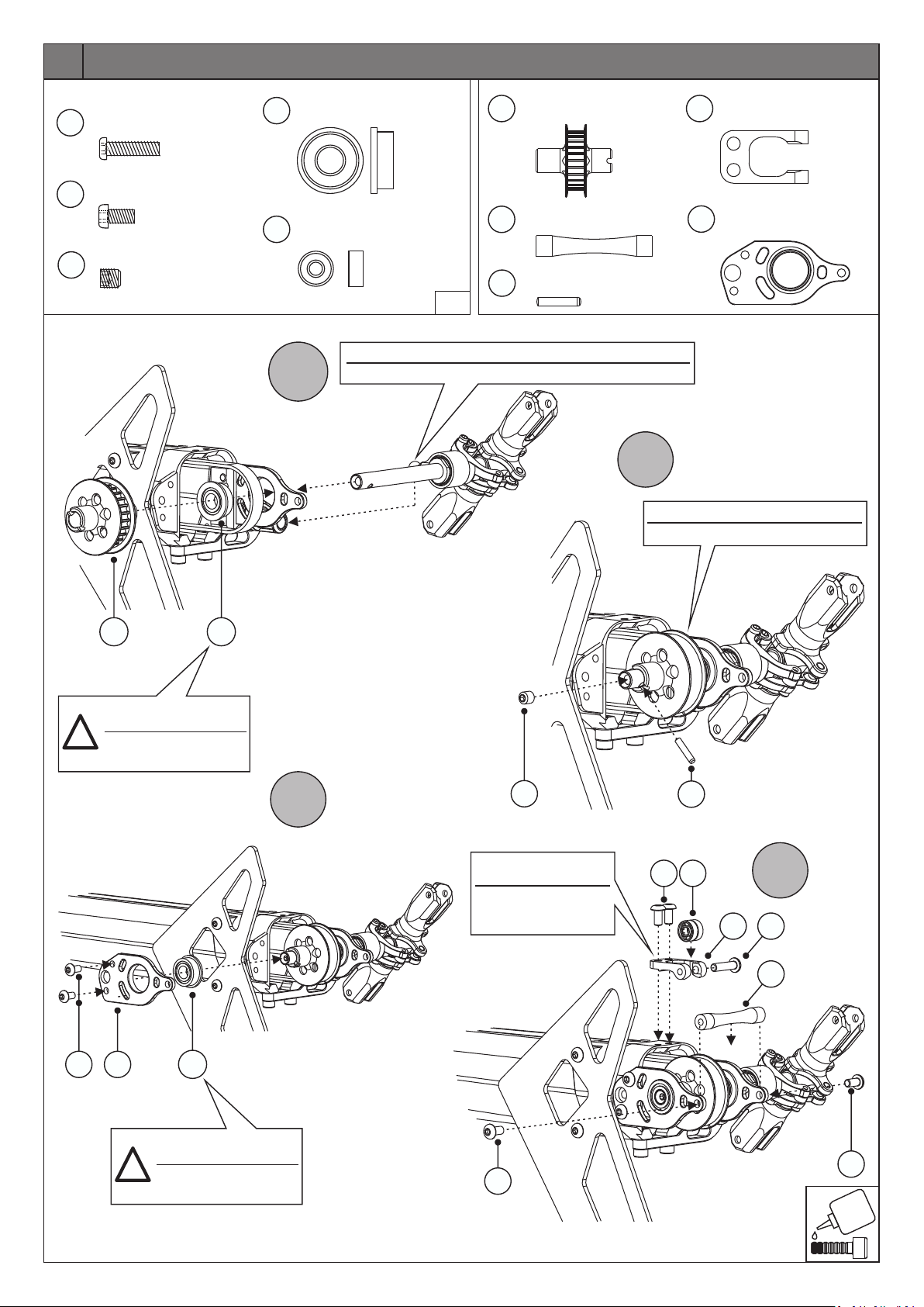
21
Normteile/Standard Parts
M3x12
M3x6
M4x4
Rundkopfschraube
Round Head Screw
Rundkopfschraube
Socket Head Screw
Gewindestift
Set Screw
1600
155
33
6x13x5
3x8x3
Flanschlager
Flanged Bearing
Kugellager
Ball Bearing
376
1x
6x
1802
1x
2x
1769
1770
2x
1774
Heckantriebsrolle 26Z
Tail Drive Pully 26T
Distanz Heckgehäuse
Spacer Tail Rotor Housing
2x10
Bolzen
Pin
1x
1x
1x
Kugellagerhalter
1772
Bearing Stand
Seitenplatte Heckgehäuse
1767
Tail Rotor Housing Side Plates
1x
1x
1:1
Kugelbolzen 145 zugleich in Steuerhebel 266 einfahren.
A
Insert ball-end screw 145 into tail lever 266 as you assemble.
B
Heckantriebsrolle in Heckriemen einsetzen.
Insert tail drive pully into tail drive belt.
1769
Kugellager 376 mit
Sicherungslack einkleben
!
Glue in ball bearings 376
with strong threadlocker
1767
155
376
376
C
33
Seitlich ausrichten damit
Riemenrad nicht streift.
Adjust sideways position so
that the drive pulley flange
does not brush against it.
155
1774
1802
1772
D
1600
1770
Kugellager 376 mit
Sicherungslack einkleben
!
Glue in ball bearings 376
with strong threadlocker
155
155
Page 20
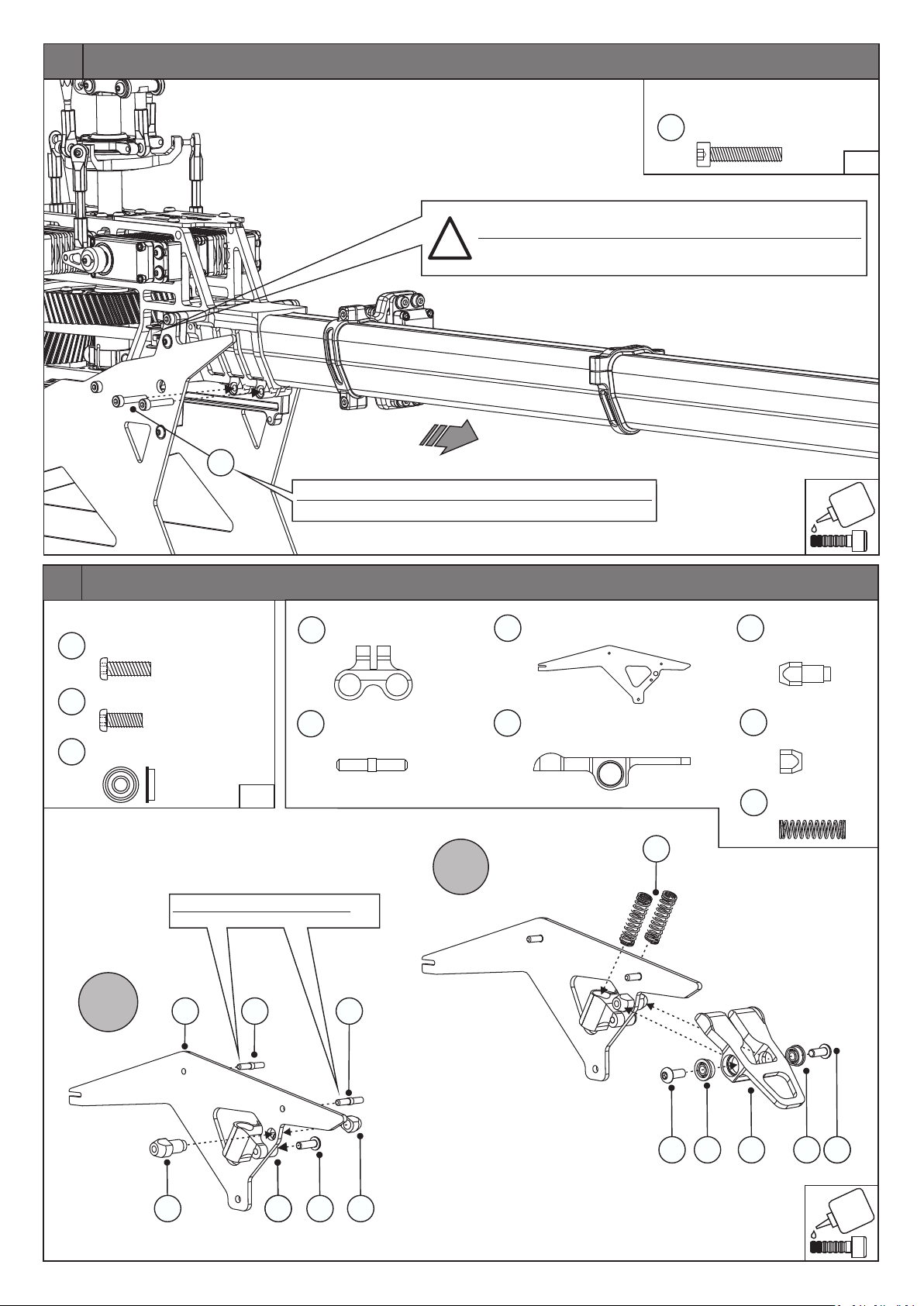
22
77
Heckriemen spannen: Riemen spannen, bis Riemenspanner
vollständig am äusseren Anschlag ist, aber nicht überspannen!
Tighten tail drive belt: Tension the belt until the belt tensioner is
!
touching the outer stop, but do not over tension!
Heckriemen spannen und danach mit Schrauben 77 klemmen.
After adjusting the belt, clamp the tail boom with screws 77.
Normteile/Standard Parts
M3x16
77
Zylinderkopfschraube
Socket Head Screw
2x
1:1
23
Normteile/Standard Parts
M3x10
M3x8
3x7x3
Rundkopfschraube
Round Head Screw
Rundkopfschraube
Round Head Screw
Flanschlager
Flanged Bearing
Mit Sekundenkleber eindrehen!
Use CA to secure the pins!
1783
1684
354
54
A
Federhülse
1805
1695
Spring Sleeve
Stift 2.5x15mm
Pin
1x
2x
2x
1:1
1695 1695
1x
2x
B
Haubenhalter
1783
Canopy Holder Carbon
Sicherheitshebel
1806
Safety Lever
1804
1x
1x
1807
1808
1804
Stehbolzen
Stud Bolt
Mutter
Nut
Druckfeder
Pressure Spring
1x
1x
2x
1806 168418051807 1808
354 354
1806
5454
??
Page 21
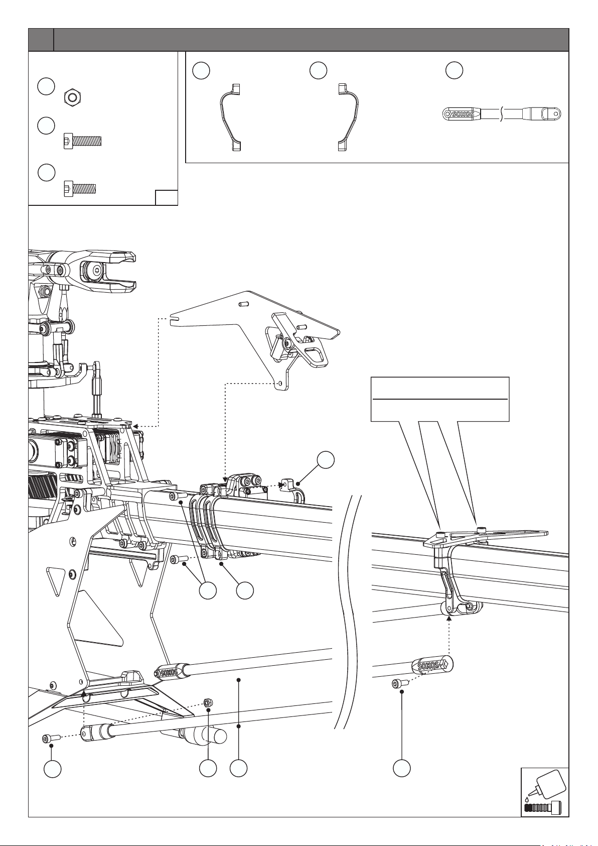
24
Normteile/Standard Parts
M3
18
71
303
Stoppmutter
Lock Nut
Zylinderkopfschraube
M3x10
Socket Head Screw
M3x8
Zylinderkopfschraube
Socket Head Screw
2x
4x
2x
1:1
1778
Halterklemme
Holder Clamp
1779
Halterklemme M3
Holder Clamp M3
1x
1x
389
Heckstrebe
Tail Brace Tube
2x
71
Mit diesen Schrauben erst nach
Montage der Heckstreben anziehen.
Clamp with these screws after
having installed the tail brace tubes.
1779
1778
71
18
389
303
Page 22
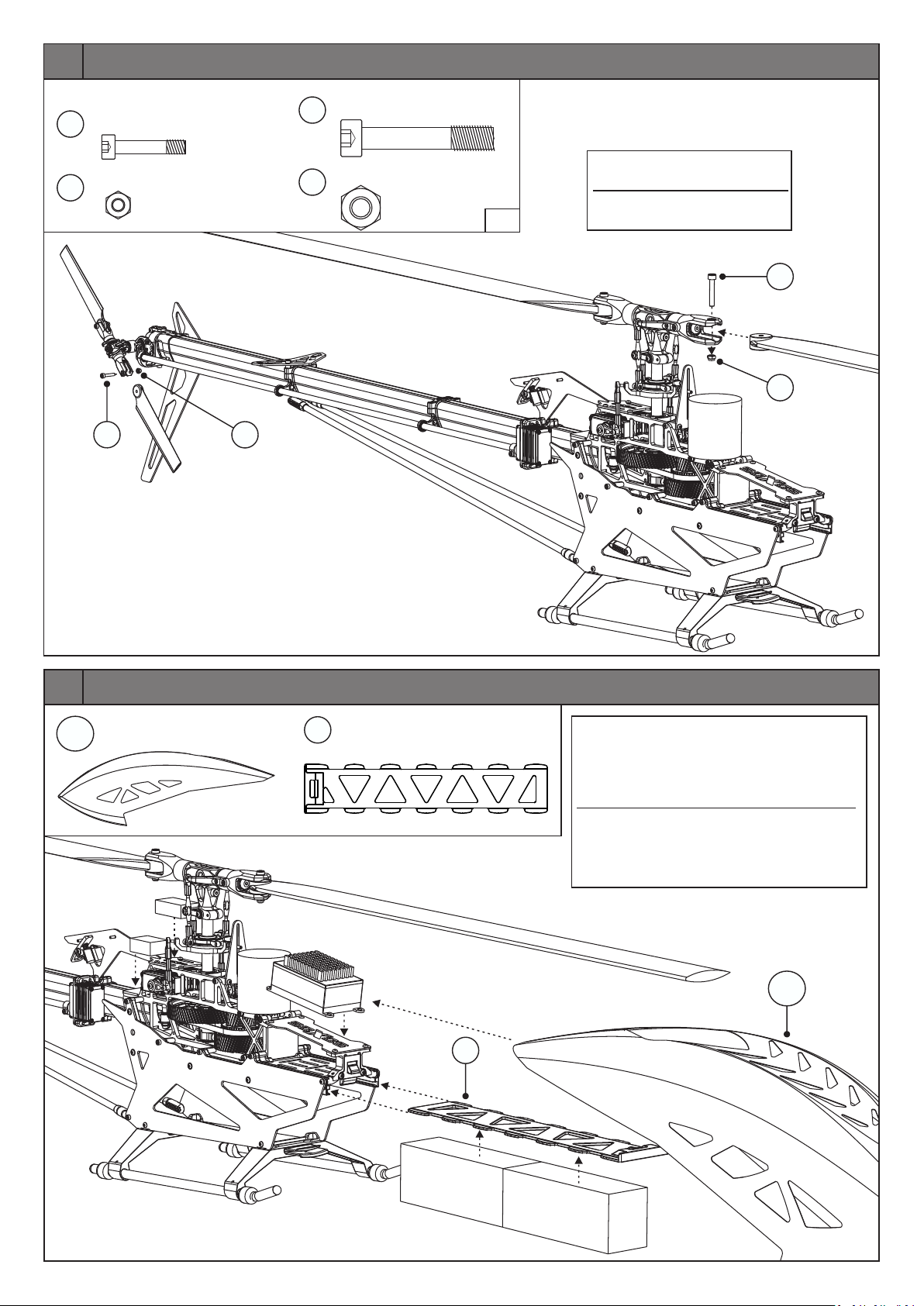
25
Normteile/Standard Parts
M3x16
510
18
M3
Tail Blade Screw
Stoppmutter
Lock Nut
510
18
M5x30
423
2xHeckrotorblattschraube
427
M5
2x
Blatthalterschraube
Blade Screw
Stoppmutter
Lock Nut
2x
2x
Haupt- und Heckrotorblätter sind
nicht im Lieferumfang enthalten.
Main and tail rotor blades are
1:1
not included in the kit.
423
427
26
C7.1
259
Haube Strike 7.1
Canopy Strike 7.1
OPTIONAL
RX
OPTIONAL
FBL
1x
517
Akkuplatte
Battery Plate
1x
Justieren Sie die Balance des Helikopters mit der
Positionierung des Akkus auf der Akkuplatte
(inkl.Haube). Verwenden Sie das mitgelieferte
Klettband, um den Akku zu sichern. Der Akku darf
sich während des Fluges nicht verschieben.
Adjust the helicopter‘s balance with the position
of the battery pack on the battery plate (incl.
canopy). Use the supplied Velcro to secure the
battery, the pack must not shift during flight.
OPTIONAL
E
SC
OPTIONAL
259
C7.1
517
OPTIONAL
Akku/Bat
t
ery
Akk
OPTIONAL
u/Ba
t
tery
Page 23
26
Page 24

Für Ihre Notizen / For your notes:
______________________________________________
______________________________________________
______________________________________________
______________________________________________
______________________________________________
______________________________________________
______________________________________________
______________________________________________
______________________________________________
______________________________________________
______________________________________________
______________________________________________
______________________________________________
______________________________________________
______________________________________________
______________________________________________
______________________________________________
______________________________________________
______________________________________________
Besuchen Sie unsere Homepage www.soxos-heli.com
Dort sind Ersatzteile wie Rotorblätter, Tuningteile, Werkzeuge,
Motoren, Regler, Akkus und Gyros erhältlich.
Die neueste Version dieses Handbuchs können Sie downloaden.
Visit our homepage www.soxos-heli.com
Spare parts such as rotor blades, tuning parts, tools,
motors, controllers, batteries and gyros are available there.
You can download the latest version of this manual.
 Loading...