


Pag.1
CONGRATULATIONS
Dear Owner,
Thank you for buying a SOVEMA manufactured product.
Your new machine is carefully designed and manufactured to give you
superior performance and dependable service, if properly operated and
maintained.
You will find this machine to be rugged and reliable when matched to
the suggested horsepower operating range.
Much time has been invested in providing safety and protection. Please
carefully read this manual. It tells you how to safely and easily assemble,
operate and maintain your machine.
Be sure that you and any other operator carefully follow the recommended safety practices at all times. Failure to do so could result in personal injury or property damage.
Of course, if you should ever have any problems or questions, please
contact your local SOVEMA dealer or contact us at the addresses or
numbers indicated in this manual.
SOVEMA manufactures a variety of innovative equipment. If you are
interested in reviewing our full line, please contact us.
Thanks for your choice.
Ginettino Mayer
President

Pag.2
TABLE OF CONTENTS
- SYMBOLS Page 3
- GENERAL INFORMATION Page 4
- SAFETY AND WARNING DECALS Page 5
- SAFETY INSTRUCTIONS Page 7
- MAIN CHECK Page 10
- TECHNICAL SPECIFICATIONS Page 11
- ATTACHING THE MACHINE TO THE TRACTOR Page 12
- CUTTING HEIGHT ADJUSTMENT Page 16
- BEGINNING WORK Page 18
- TROUBLE SHOOTING Page 19
- DISCONNECTING THE MACHINE FROM THE TRACTOR Page 22
- STORING OF THE MACHINE Page 23
- MAINTENANCE Page 24
- TOXICOLOGICAL INFORMATION Page 27
- SPARE PARTS LIST Page 29
- WARRANTY POLICY Page 36
- SOVEMA PRODUCT LINE Page 40

Pag.3
MEANS: CAUTION!
YOUR SAFETY IS INVOLVED
MEANS: USE PROTECTIVE GLOVES
MEANS: READ CAREFULLY
SYMBOLS
These symbols appear throughout the manual.
Remember their meaning and advice.

Pag.4
GENERAL INFORMATION
All implements with moving parts are potentially hazardous. The manufacturer has designed
the implement to be used with all the safety equipment properly attached. The purpose of this
manual is to assist you in safety maintaining and operating the implement.
These instructions have been compiled from our experience.
Through this experience and these instructions, you should be able to develop operating procedures suitable to your particular situation.
Illustrations and data used in this manual may vary slightly in some details. Throughout this
manual references are made in left and right directions. These are determined by standing at the
rear of the equipment and facing the direction of forward travel.
Even if some illustrations in this manual show the machine
with safety shields removed for a better view, never operate in
these conditions.
BEFORE OPERATING THE IMPLEMENT, ALL SAFETY
SHIELDS OR DEVICES MUST BE MOUNTED
RIGHT
LEFT

Pag.5
SAFETY AND WARNING DECALS
Safety decals on the implement contain important safety warning messages. To prevent injuries
we invite the operator to read them carefully and keep them clear. Check that all the decals are on
the machine. If not, DO NOT USE the machine and report to the Dealer immediately to get the
decals. Decals on the machine are the following and mean:
1 2 3 4
1. Before operating the equipment, read carefully the operator’s manual.
2. Before maintenance operation, lower the implement, shut off the engine and read the
operator’s manual.
3. Do not allow riders on tractor or implement.
4. Do not stand behind the tractor during the operations.
5. Before operating the equipment, read carefully the operator's manual.
6. DANGER! Entanglement of driveline..
7. KEEP AWAY from driveline in operation: contact can
cause death!

8. Danger. Your hands and feet can be injured by moving parts. Keep away from the implement.
9. Danger. Your hands can be injured. Do not remove the cover and keep away from
moving parts.
10. The machine is designed for use on tractors with 540 RPM PTO
only
11. The machine is designed for use on tractors with 1000 RPM
PTO only
12. The machine is designed for use on tractors with 2000 RPM
PTO only
13. Caution! During working operations all bystanders must stay beyond the shown distances
from the implement.
Pag.6
8 9

Pag.7
SAFETY INSTRUCTIONS
Before using the implement you must be sure to know the main safety precautions; in fact many
accidents are caused by not observing these rules.
Pre-operational and operational safety rules
Make sure that no person operates this machine unless they first, thoroughly read and
studied the operator instructions for this machine and understood all the safety precautions.
Keep all guards, shields and safety decals in place and proper working order before operating this machine.
Operate only with a tractor equipped with an approved Roll Over Protective System
(ROPS) and always wear your seat-belt.
Operate only in daylight or good artificial light.
Only trained personnel can operate with the tractor and the implement.
Personal protection equipment, including safety shoes, safety glasses, hard hat and
gloves are recommended during the different operations. Do not allow long hair, loose
fitting clothing or jewellery to be around moving parts.
Do not leave the tractor seat until the engine is completely turned off, brakes locked
and ignition key removed.
Do not allow riders on the machine or tractor at any time. No safe place for any rider.
Before starting to operate, be sure that the tractor's PTO is set to match the PTO requirements of the implement. The speed is indicated in this manual and on the implement.
Do not use different driveline . Always use type and size supplied by the manufacturer.
Make sure driveline spring-activated locking pin operate freely and are seated firmly in
tractor PTO stub shaft groove.

Pag.8
For engaging or disengaging the tractor PTO, refer to your tractor manual.
Connect and disconnect PTO shaft only when tractor engine is turned off.
Keep hands, feet, hair and clothing away from moving parts.
To prevent injury by thrown objects DO NOT operate unless all personnel, livestock and
pets are 20 m (65 ft) away.
The rotating parts of the machine have been designed and tested for rugged use. However
they could fail upon impact with heavy solid objects. Such impact could cause the broken
objects to be thrown outward at very high speed. To reduce the possibility of serious injury, or even death, never allow the rotating parts to contact such obstacles.
Stop the machine and tractor immediately upon striking an obstruction. Turn engine off,
remove key, inspect and repair any damage before resuming operation.
No repairs or adjustments should be attempted while the machine is attached to a tractor
that is turned on.
Working inclination of PTO driveline must not exceed 25° (see fig.1). Greater working
angles will damage the PTO and serious personal injury could occur as well.
Disengage tractor PTO and place transmission into neutral before attempting to start engine.
Transport safety
Plan your route to avoid heavy traffic.
For public roads, comply with state and local safety and movement rules.
Be sure that the implement is in the raised position for transport.

Pag.9
When you must drive, do not drink.
Pay attention to traffic when operating near or crossing roadways.
Reduce speed when transporting mounted implement to avoid bouncing and loss of steering control.
Pay attention when you turn curves or you go up and down on hills with the implement.
Be sure that at least 25% of the tractor’s weight is on the front wheels to maintain safe
steering. Drive at a low speed.
NEVER allow riders on implement or tractor. Falling off can kill.
Be a safe and courteous driver.
Maintenance safety
Good maintenance is your responsibility. Poor maintenance is an invitation to trouble.
For maintenance follow these common practises:
- keep service area clean;
- use adequate illumination for the job;
- be sure tools and electrical outlets are properly grounded;
- make sure there is plenty of ventilation.
Before making maintenance on this machine, drive to a level area, disengage the PTO,
lower the machine, turn off the engine, set the brakes and remove the ignition key.
Keep all persons away from operator control area while performing maintenance.
ALWAYS use personal protection devices.
Periodically tighten all bolts, nuts and screws.
The implement manufacturers assumes no liability if replacement parts other than the
original factory parts are used.
After servicing, be sure that all safety shields are re-installed properly.
Be sure that all safety decals are installed, clean and in good condition.
If the machine is modified from the original design, no responsibility for the manufacturer
can be claimed.

Pag.10
MAIN CHECK LIST
Before connecting the machine to the tractor, read the following instructions:
• Be sure the weight and power of the tractor is co rrect with the machine you want to con-
nect. If you have any doubt, see the technical specifications.
• Ensure that all safety decals are properly installed and clean.
• Check oil in the gearbox. With low oil, gears get damaged.
• Be sure that all safety shielding is properly installed and in good condition.
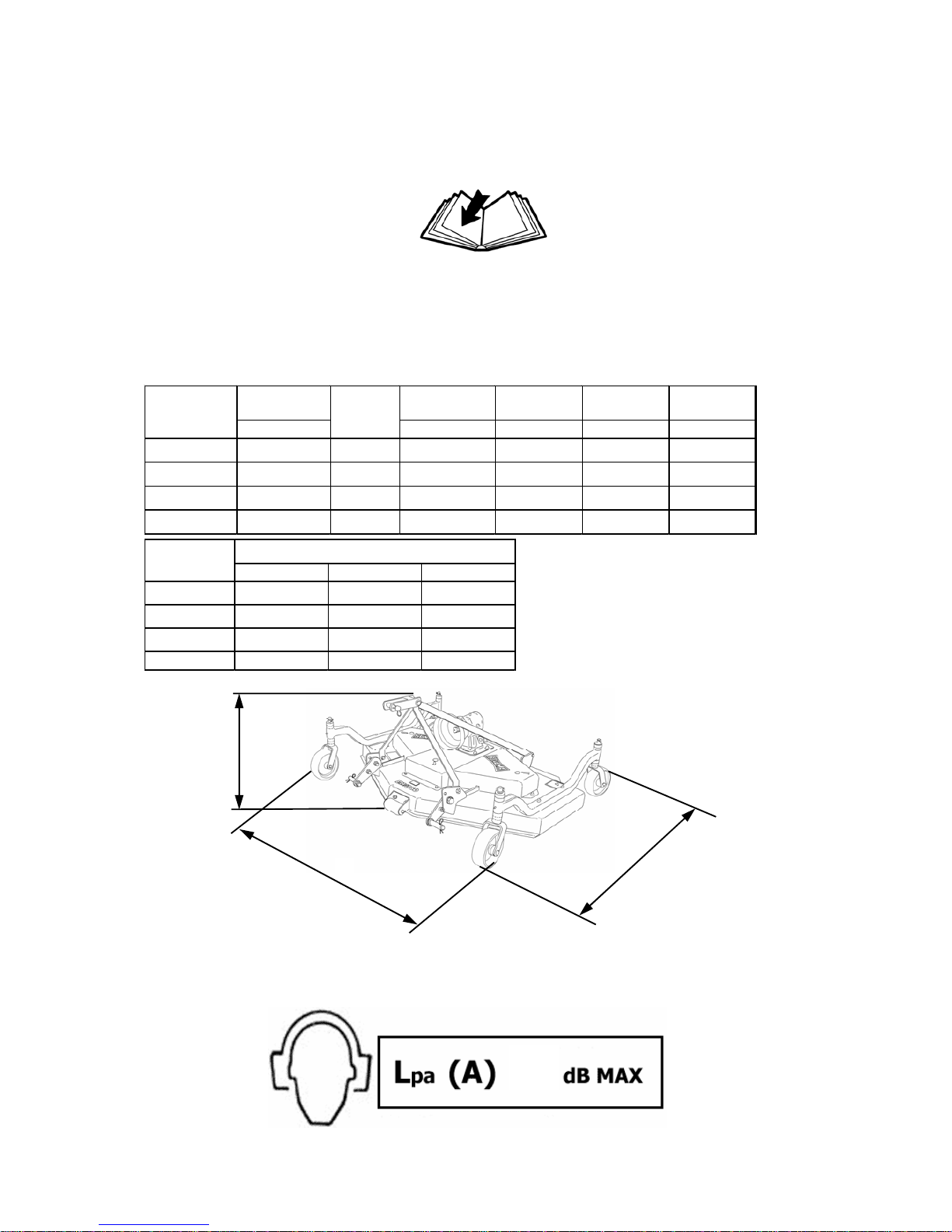
TECHNICAL SPECIFICATIONS
The machine described in this manual is a grass cutter of the EM 3 series.
EM 3 SERIES
LEVEL OF NOISE RESULT WHEN IDLING
A
B
C
Pag.11
84
Working width Weig ht Width -A- He ight -B - Depth -C -
cm/inches Kg./Lbs. cm/inches cm/inches cm/inches
EM-3 48
120 / 48" 20 - 40 172 / 387 134 / 53" 72 / 28" 119 / 47"
EM-3 60
150 / 59" 25 - 45 201 / 452 162 / 64" 72 / 28" 134 / 53"
EM-3 72
180 / 72" 30 - 50 257 / 578 194 / 76" 72 / 28" 155 / 61"
EM-3 84
208 / 82" 35 - 50 294 / 662 220 / 87" 72 / 28" 173 / 68"
MOD. HP
Pto 540 ( rpm ) Pto 1000 ( rpm ) Pto 2000 ( rpm )
EM-3 48
3265 3128
3175
EM-3 60
2690 2576
2615
EM-3 72
2285 2190
2220
EM-3 84
2285 2190 2220
MOD.
Rotor

ATTACHING THE MACHINE TO THE
TRACTOR
The machines described in this manual do apply to any kind of tractor provided of universal
third hitch point.
The characteristics (length, diameter of the holes for the lifting pins) of the tractor’s lifting arms
depend on the type of tractor, therefore it is necessary to prepare the machine in order to conclude the attachment correctly.
Before attaching the machine to the tractor you must be sure that the engine is turned off, brakes
are locked and the ignition key is removed.
This operation must be made on a flat area as it is very dangerous.
Do not allow anyone between tractor and implement when the
engine is running.
Follow these instructions:
Connect the hitch of the drawbar to the tractor using a hitch pin and the hair clip pin (see
fig. 1)
LOWER
PLATES
FIG. 1
Pag.12

Pag.13
Connect the hitch point of the tractor to the floating upper plates of the machine using a
hitch pin and the hair clip pin (see fig. 2). This connection must guarantee a 15° inclination of the upper plates (see fig. 3) in order to let the machine adapt to the terrain and to
protect its frame from possible damage. The inclination is obtained by regulating the tie
rod of the hitch point of the tractor.
Connect the PTO shaft and be sure it is correctly connected to the tractor and the machine (see fig.4).
FLOATING UPPER
PLATES
FIG. 2
FIG. 3
FIG. 4

Pag.14
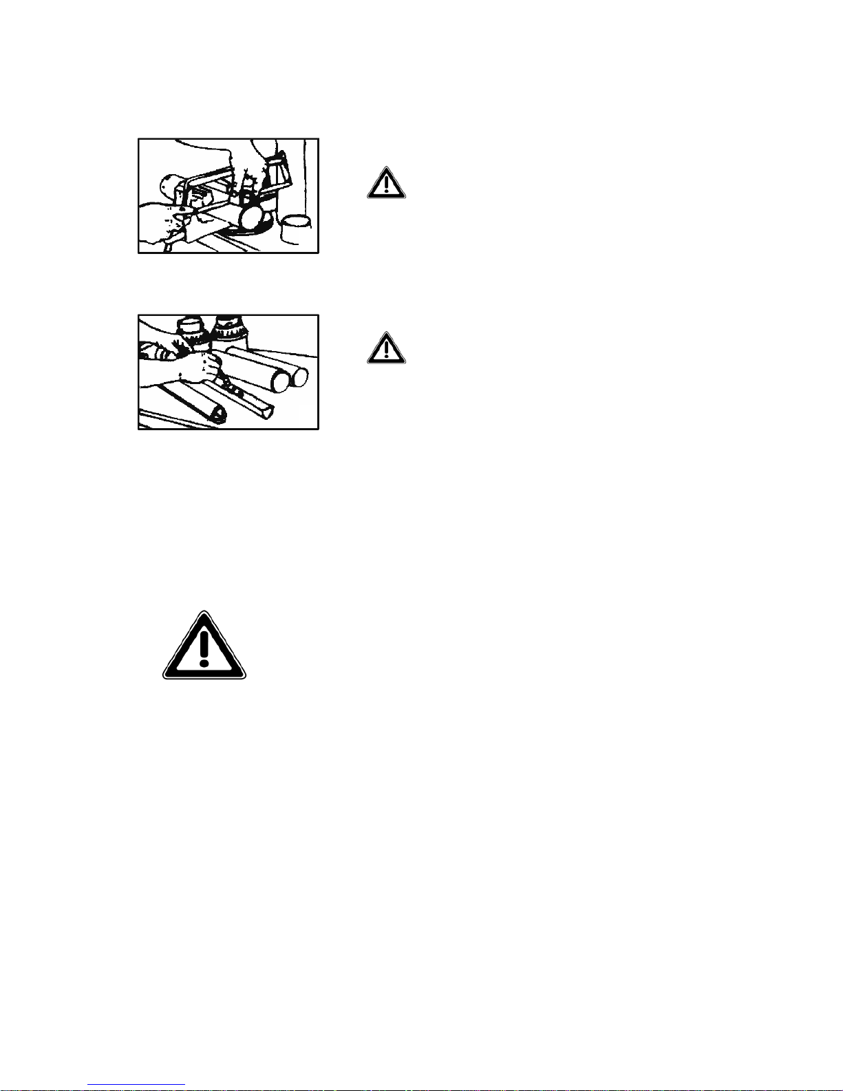
Shortening the PTO shaft
Due to the many different types of tractors, it may be necessary to shorten the PTO shaft.
Always refer to the manual of the driveline’s manufactures. Read it carefully.
In case shortening is needed, listed below are some basic guidelines on performing this modification. Determine how much
length is to be removed, then:
1) Remove plastic protection (both sections)
2) Cut the excess length of both tubes
3) Deburr and clean the saw-dust off ends
of tubes. Remove packing inside shaft
tubing
1
2
3
Pag.15
4) Cut the plastic protection to the same
length you have cut the joints
5) Grease the male joint section and reassemble protection
Do not use PTO shafts without proper shielding installed.
4
5

CUTTING HEIGHT ADJUSTMENT
To adjust the cutting height of your machine, follow the next instructions (see fig. 1):
•
For each wheel unthread the split pin from the fork in which the cutting height regulation
spacers are threaded.
• If you wish to increase cutting height, add spacers under the bush of the support arms, for
each wheel.
• If you wish to reduce cutting height, add spacers over the bush of the support arms, for
each wheel.
• After concluding regulation as desired, insert the split pins in its respective forks.
To get uniformity on cut, the regulation described before
(by spacers) must be the same for the four wheels of the machine.
Pag.16
SUPPORT
ARSM
FIG. 1
BUSH
SPACERS
SPLIT PIN
WASHER

If your machine is equipped with a rear roller instead of the two wheels, the regulation is
carried out by unthreading the split pins from the forks of the two front wheels and from
the two frame-supports of the roller, to proceed by using the spacers, as explained before
(see fig. 2).
To get uniformity on cut, after regulating as explained before
(by rear roller), be sure the machine results parallel to terrain.
Minimum cutting height possible (following the two types of regulation) is 2,5 cm; the maximum possible is 12 cm.
REAR ROLLER
FIG. 2
Pag.17
FRAME SUPPORT

BEGINNING WORK
After completing all safety controls, and being sure the machine is set out parallel to terrain (see
fig. 1), to avoid damage start as follows:
• Raise the machine off the ground in order to let the knives start moving without touching
ground.
•
Maintaining the machine raised, engage the tractor PTO at suggested engine RPM.
•
Start moving the tractor forward and then gradually lower the machine.
Cutting tips
Proper ground speed for cutting will depend upon the height, type and density of the grass to be
cut. However we suggest not to exceed 7 Km/h. Lower ground speed allows tall and dense grass
cutting. Taking a partial cut and/or reversing the direction of travel may also produce a cleaner
cut. Remember, sharp knives produce cleaner cuts and require less power.
To avoid damage to frame and gearbox as a consequence of impact of the knives with soil or solid objects, it is advisable not
to carry out very low cuts.
Pag.18

TROUBLE SHOOTING
During work several problems can happen:
Unusual noise
While working, if the machine made unusual noise, the operator must stop it immediately
and follow next instructions:
• Check for broken/bent parts.
• Check for correct o il level in the gearbox case.
When present incorrect oil level (see chapter on maintenance), the gears of the gearbox are
not lubricated correctly, and if continue to rotate, would determine a significant increase in
oil temperature. If continue working in this condition will quickly take to damage gear
bearings with consequent blocking of the PTO shaft.
•
Check knives conditions.
If one of the knives is broken or excessively worn, continuing to rotate in short time takes to
damage one of the two bearings (or both) of the shaft in which the knife is fixed. The shaft
begins to oscillate producing great vibration, and in short time finishes to damage the weldings of the frame itself.
• Check condition of the bearings that support the rotor shaft hubs.
As a result of inadequate lubrication (see chapter on maintenance), it is possible that a bearing of one of the rotor shaft hubs has been damaged. The rotor shaft begins to oscillate causing excessive vibration of the frame, and in short time causing damage of its weldings.
Pag.19

Cutting defects
After work, if cut doesn’t result uniform and clean, follow next instructions:
• Check knife conditions.
In case of worn knives, you need to replace them (see chapter on maintenance).
• Check that cutting heig ht adju stment has been done correctly.
It is possible that the cutting height adjustment by spacers has not been done in the same way for
the four wheels. Or it is possible that the versions equipped with rear roller, after the adjustment,
the machine and its knives have not been displayed parallel to ground.
After work, if cut doesn’t result clean the operator must stop the machine and check belt condition after removing the cover that protects them. In fact, there is a possibility of belt sliding, not
letting the knives cut with adequate power. Belt sliding occurs when lack of tension itself (belt
going too slow) or belt wear (see chapter on maintenance).
-If belts give signs of deterioration (even of small entity), immediate replacement is required.
-If belts are slow, immediate tensioning is required.
If after work the cut doesn’t present clean, it is possible that the machine’s going speed is not
opportunely adequate to the number of turns the rotor does, and therefore to the cutting speed of
the knives. Often happens that speed of the machine doesn’t give enough time to the knives for a
correct cutting.
In the case tall grass is being cut and ground speed is too high, it
is possible that grass accumulates between the frame and the
knives, taking to decrease efficiency in the cutting itself (see
Cutting Tips).
Pag.20

Unloading defects
If the operator of the machine finds difficulty on unloading the product just cut, stop and follow these instructions:
- Verify the presence of wet grass and mud under the frame.
In fact it is possible that grass and mud get stuck in the lower part of the frame, interfering
with the unloading function.
- Verify that grass or other solid object are not stuck around the knives.
Before checking the machine to find the possible cause of malfunctioning, be sure the tractor’s PTO is disconnected, tractor’s
engine turned off, brakes on, key ignition off the command
board, and the machine completely lowered to the ground.
Pag.21

Pag.22
DISCONNECTING THE MACHINE FROM
THE TRACTOR
Disconnecting of the machine must be carried out on flat area, and it is considered a very
dangerous operation. You must pay attention. Follow these instructions:
While remaining in the tractor seat, put the tractor PTO in neutral.
When the rotors are completely stopped, turn off the engine and set the parking brakes.
Remove the ignition key.
Descend from the tractor and disconnect the driveline.
Engage the parking stand.
Disconnect the hitch of the drawbar from the tractor.
Before disconnecting the driveline, be sure the tractor PTO is in
neutral and engine is off.

Pag.23
STORING OF THE MACHINE
As your machine is an investment and if remains unused for a long period, we suggest the following procedures:
•
Wash and dry the machine;
•
Check all moving parts. For excessive wear replace the parts or contact your local dealer;
•
Check bolts and nuts for proper tightness;
•
Accurately grease the bearings of the rotor shaft hubs and the bushes of the support arms of
the wheels;
•
For versions equipped with rear roller, grease the lateral supports of the roller itself.
•
Lubricate all not-painted parts;
•
Store the machine in a clean and dry place under roof.

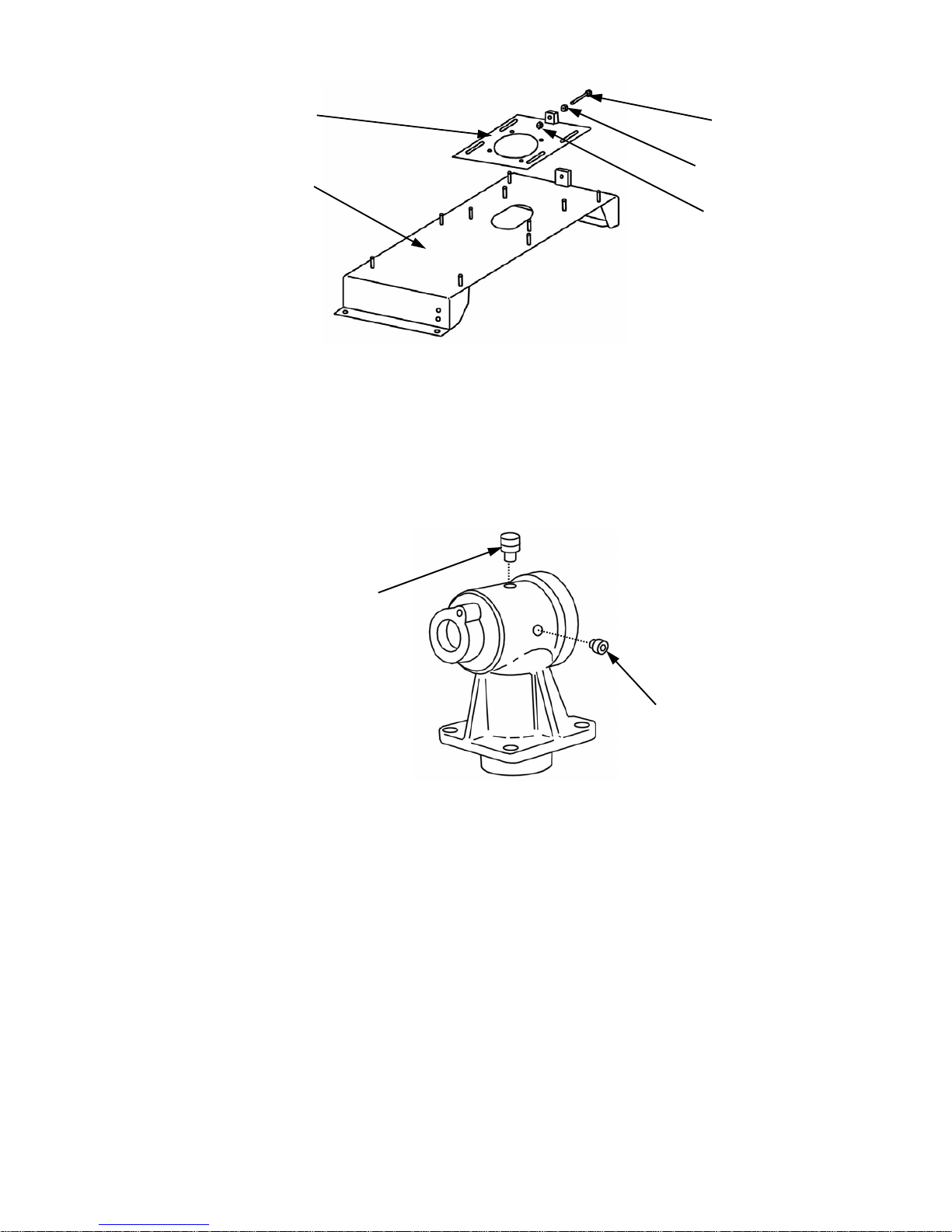
MAINTENANCE
For long life of your machine and trouble free operation, regular program of maintenance is required.
The recommended phases of maintenance are for normal use and can be varied depending on the
different conditions.
Always disengage tractor PTO before starting maintenance.
Every 10 working hours
•
Check for loose screws that fix the knives;
•
Grease the PTO shaft components;
• Clean the end of PTO shaft with non toxic / non inflammable detergent;
• Be sure driv eline shields are in place and in good condition;
• Using the grease nipples located on top of the rotor shaft hubs (one for each shaft) and ex-
actly under the plugs present on the covers, grease the bearings of the shafts it selves. To
carry out this operation take out the plugs from the covers and clean the grease nipples. Use
grease of lithium NLGI 2;
• Clean the machine.
Pag.24

Every 20 working hours
•
Grease the bushes of the support arms of the wheels (see fig. 1). Before carrying this out
clean grease nipples accurately. Use lithium grease NLGI 2.
•
Check belt tensioning by measuring belt tightness. Correct tightness results when belt deflection along the front side of the belt is 1 cm, as a result of the pressure applied with the
index finger to the centre of the belt length (see fig. 2).
the case belt adjustment was needed, proceed as follows (see fig. 3) for each stretcher:
• Unscrew the four screws that fix the case plate to the support;
• Unscrew the counter nut and rotate clockwise the blocking plug, maintaining the tension-
ing screw fixed with a wrench;
• After regulating the tensioning, screw back the counter nut;
• Screw back the four screws that fix the case p late to the support.
Pag.25
Grease nipple
FIG. 1
MAX 10 mm
FIG. 2
•
Be sure knives are sharpen uniformly. If necessary substitution, replace with original
knives.
• Check gearbox correct oil level. To proceed, remove the oil level screw (see fig. 4). If
needed to add oil, remove the filler screw located on top of the box, and fill in until oil
starts running out of the level hole.
Every 50 working hours
•
For those versions of the machine equipped with rear roller, proceed to grease its lateral
supports. Before greasing, clean the grease nipple correctly for better lubrication. Use lithium type grease NLGI2.
First 100 working hours
•
When the machine has done its first 100 hours, change the oil from the gearbox. To proceed, drain all the oil through the level screw hole after leaning opportunely the machine,
then fill in with new oil through the filler hole. This substitution is necessary because the
gears are new and so are subject to quicker worn. Use oil SAE 80 W 90 API GL4.
Pag.26
CASE
SUPPORT
TENSIONING
SCREW
COUNTER NUT
BLOCKING
NUT
FIG. 3
FILLER
SCREW
LEVEL SCREW
FIG. 4

Every 100 working hours
• Check the superficial state of the wheels. These are made of full rubber and are subject to
worn after a while.
Every 200 working hours
• Replace the belts. Actually this substitution is necessary when belts present cuts or evident
worn signs. To proceed with replacement follow these instructions:
a) Before replacement check condition of the pulleys and bearings;
b) Clean the pulleys from residual material of the old belts;
c) Be sure pulleys rotate liberally and firmly;
d) Tension belts correctly (see chapter on Trouble Shooting).
Every 300 working hours
• Completely replace gearbox oil, proceeding as explained before. Use oil SAE 80 W 90
API GL4.
TOXICOLOGICAL INFORMATION ABOUT
LUBRICANTS
Pag.27
TYPES OF DANGER
PROTECTIVE EQUIP-
MENT
PRIMARY INTERVEN-
TION
SKIN
Possible irritation after
prolonged contact
Gloves and/or lotion barrier
Wash with soap & water
EYES
Possible irritation on contact
Protective goggles
Rinse thoroughly w/ running water
INHALATION
Possible irritation after
prolonged exposure
Maintain an oil mist level
of 5mg/m3 between TLVTWA limits
Expose to fresh air and
call medical assistance
immediately
INGESTION
Such possibility not considered
DO NOT provoke vomiting; call medical assistance immediately

USE EXLUSIVELY ORIGINAL
SPARE PARTS FROM
SOVEMA
Pag.28

SPARE PARTS LIST
EM-3 Model
Pag.29

EM 3
Frame
Pag.30

Pag.31
REF CODE QTY ENGLISH FRANÇAIS ITALIANO DEUTSCH ESPAÑOL NOTE
1 900.241.504 1 FRAME CHASSIS TELAIO RAHMEN BASTIDOR 48
1 900.241.505 1 FRAME CHASSIS TELAIO RAHMEN BASTIDOR 60
1 900.241.506 1 FRAME CHASSIS TELAIO RAHMEN BASTIDOR 72
1 900.241.507 1 FRAME CHASSIS TELAIO RAHMEN BASTIDOR 84
3 900.241.519 1 PLATE PLAQUE PIASTRA PLATTE PLACA
5 900.241.530 1 SUPPORT SUPPORT SUPPORTO STUETZE SOPORTE 48-60-72
5 900.241.531 1 SUPPORT SUPPORT SUPPORTO STUETZE SOPORTE 84
6 900.241.515 2 ARM BRAS BRACCIO ARM BRAZO 48
6 900.241.516 2 ARM BRAS BRACCIO ARM BRAZO 60
6 900.241.517 2 ARM BRAS BRACCIO ARM BRAZO 72
6 900.241.518 2 ARM BRAS BRACCIO ARM BRAZO 84
7 900.241.520 1 CONVEYOR DEFLECTEUR DEFLETTORE KONVEYOR DEFLECTOR 48
7 900.241.521 1 CONVEYOR DEFLECTEUR DEFLETTORE KONVEYOR DEFLECTOR 60
7 900.241.522 1 CONVEYOR DEFLECTEUR DEFLETTORE KONVEYOR DEFLECTOR 72
7 900.241.523 1 CONVEYOR DEFLECTEUR DEFLETTORE KONVEYOR DEFLECTOR 84
8 900.241.512 1 SUPPORT SUPPORT SUPPORTO STUETZE SOPORTE 48
8 900.241.513 1 SUPPORT SUPPORT SUPPORTO STUETZE SOPORTE 60
8 900.241.514 1 SUPPORT SUPPORT SUPPORTO STUETZE SOPORTE 72-84
9 900.241.508 2 COVER CARTER CARTER GEHAEUSE CARTER 48
9 900.241.509 2 COVER CARTER CARTER GEHAEUSE CARTER 60
9 900.241.510 2 COVER CARTER CARTER GEHAEUSE CARTER 72
9 900.241.511 2 COVER CARTER CARTER GEHAEUSE CARTER 84
10 900.241.532 1 ROLLER ROULEAU RULLO WALZE RODILLO 48-60-72
10 900.241.533 1 ROLLER ROULEAU RULLO WALZE RODILLO 84
11 900.241.524 2 TIE ROD TIRANT TIRANTE ZUGSTANGE TIRANTE
12 900.241.525 2 TIE ROD TIRANT TIRANTE ZUGSTANGE TIRANTE 48
12 900.241.526 2 TIE ROD TIRANT TIRANTE ZUGSTANGE TIRANTE 60
12 900.241.527 2 TIE ROD TIRANT TIRANTE ZUGSTANGE TIRANTE 72
12 900.241.528 2 TIE ROD TIRANT TIRANTE ZUGSTANGE TIRANTE 84
13 900.241.529 2 HITCH ATTELAGE ATTACCO ANBAU ENGANCHE
14 900.104.059.T 4 WASHER RONDELLE RONDELLA ZWISCHENSCHEIBE ARANDELA
15 900.241.182 16 SPACER ENTRETOISE DISTANZIALE ABSTANDSRING DISTANCIADOR
16 900.241.186 4 FORK FOURCHETTE FORCELLA GABEL HORQUILLA 48-60-72 USA
16 900.241.539 4 FORK FOURCHETTE FORCELLA GABEL HORQUILLA 84 USA
16 900.241.534 4 FORK FOURCHETTE FORCELLA GABEL HORQUILLA 48-60-72 CAN
16 900.241.535 4 FORK FOURCHETTE FORCELLA GABEL HORQUILLA 84 CAN
17 900.108.025 4 CLICK PIN CHEVILLE DECKIC SPINA A SCATTO SCHNAPPSTIFT CLAVIJA DE RES.
18 900.100.087 8 BEARING ROULEMENT CUSCINETTO KUGELLAGER COJINETE 48-60-72 USA
18 900.100.043 8 BEARING ROULEMENT CUSCINETTO KUGELLAGER COJINETE 84 USA
18 900.100.043 8 BEARING ROULEMENT CUSCINETTO KUGELLAGER COJINETE CAN
19 900.241.187 4 WHEEL ROUE RUOTA RAD RUEDA 48-60-72 USA
19 900.241.226 4 WHEEL ROUE RUOTA RAD RUEDA 84 USA
19 900.152.013 4 WHEEL ROUE RUOTA RAD RUEDA 48-60-72 CAN
19 900.234.076 4 WHEEL ROUE RUOTA RAD RUEDA 84 CAN
20 900.241.199 4 SPACER ENTRETOISE DISTANZIALE ABSTANDSRING DISTANCIADOR 48-60-72 USA
21 900.241.200 4 PIN TOURILLON PERNO STIFT PERNO 48-60-72 USA
21 900.241.227 4 PIN TOURILLON PERNO STIFT PERNO 84 USA
21 900.241.227 4 PIN TOURILLON PERNO STIFT PERNO 48-60-72 CAN
21 900.277.004 4 PIN TOURILLON PERNO STIFT PERNO 84 CAN
22 900.104.045.T 9 WASHER RONDELLE RONDELLA ZWISCHENSCHEIBE ARANDELA
23 900.102.121.T 7 SCREW VIS VITE SCHRAUBE TORNILLO
24 900.241.339 2 BELT COURROIE CINGHIA RIEMEN CINTA 48
24 900.241.340 2 BELT COURROIE CINGHIA RIEMEN CINTA 60
24 900.241.341 2 BELT COURROIE CINGHIA RIEMEN CINTA 72
24 900.268.004 2 BELT COURROIE CINGHIA RIEMEN CINTA 84
25 900.103.030.T 3 RING NUT EMBOUT GHIERA NUTMUTTER CASQUILLO
26 900.241.189.0 3 HUB MOYEU MOZZO NABE MOZO
27 900.241.319 1 PULLEY POULIE PULEGGIA REIMENSCHEIBE POLEA
28 900.241.316 1 PULLEY POULIE PULEGGIA REIMENSCHEIBE POLEA 48
28 900.241.317 1 PULLEY POULIE PULEGGIA REIMENSCHEIBE POLEA 60
28 900.241.318.0 1 PULLEY POULIE PULEGGIA REIMENSCHEIBE POLEA 72-84
29 900.241.313 2 PULLEY POULIE PULEGGIA REIMENSCHEIBE POLEA 48
29 900.241.314 2 PULLEY POULIE PULEGGIA REIMENSCHEIBE POLEA 60
29 900.241.315.0 2 PULLEY POULIE PULEGGIA REIMENSCHEIBE POLEA 72-84
30 900.241.540 1 BAR BARRE BARRA STANGE BARRA
31 900.106.017 8 CIRCLIP SERFLEX SEEGER SEEGER SEEGER 84 USA
31 900.106.017 8 CIRCLIP SERFLEX SEEGER SEEGER SEEGER CAN
32 900.116.030 2 U-BOLT MANILLE CAVALLOTTO U-BOLZEN SOPORTE
33 900.116.043 2 HITCH ATTELAGE ATTACCO ANBAU ENGANCHE
34 900.241.343 1 HITCH ATTELAGE ATTACCO ANBAU ENGANCHE
35 900.240.053 1 PIN TOURILLON PERNO STIFT PERNO
36 900.108.006 5 SPLIT PIN GOUPILLE COPIGLIA ARRETIERUNG PASADOR
37 900.102.023.T 1 SCREW VIS VITE SCHRAUBE TORNILLO
38 900.104.046.T 20 WASHER RONDELLE RONDELLA ZWISCHENSCHEIBE ARANDELA
39 900.103.019.T 1 NUT ECROU DADO MUTTER TUERCA
40 900.102.115.T 4 SCREW VIS VITE SCHRAUBE TORNILLO
41 900.104.036.T 12 WASHER RONDELLE RONDELLA ZWISCHENSCHEIBE ARANDELA
42 900.102.245.T 5 SCREW VIS VITE SCHRAUBE TORNILLO

EM 3
Frame
Pag.32

Pag.33
REF CODE QTY ENGLISH FRANÇAIS ITALIANO DEUTSCH ESPAÑOL NOTE
48 900.103.035.T 26 NUT ECROU DADO MUTTER TUERCA
49 900.116.044 2 PIN TOURILLON PERNO STIFT PERNO
50 900.102.379.T 2 SCREW VIS VITE SCHRAUBE TORNILLO
51 900.104.043.T 4 WASHER RONDELLE RONDELLA ZWISCHENSCHEIBE ARANDELA
52 900.102.254 3 SCREW VIS VITE SCHRAUBE TORNILLO
53 900.241.166 3 KNIFE COUTEAU COLTELLO MESSER CUCHILLA 48
53 900.241.167 3 KNIFE COUTEAU COLTELLO MESSER CUCHILLA 60
53 900.241.168 3 KNIFE COUTEAU COLTELLO MESSER CUCHILLA 72
53 900.241.170 3 KNIFE COUTEAU COLTELLO MESSER CUCHILLA 84
54 900.109.016 3 PLUG BOUCHON TAPPO DECKEL TAPON
55 900.241.345.2 3 SHAFT ARBRE ALBERO WELLE EJE
56 900.105.013 3 KEY CLAVETTE CHIAVETTA KEIL CHAVETA
57 900.241.346 3 DUST COVER PARE-POUDRE PARAPOLVERE STAUBDICHTUNG GUARDA POLVO
58 900.241.347 9 SPACER ENTRETOISE DISTANZIALE ABSTANDSRING DISTANCIADOR
59 900.100.043 6 BEARING ROULEMENT CUSCINETTO KUGELLAGER COJINETE
60 900.241.348 3 SPACER ENTRETOISE DISTANZIALE ABSTANDSRING DISTANCIADOR
61 900.105.015 3 GREASE NIPPLE GRAISSEUR INGRASSATORE SCHMIERNIPPEL ENGRASADOR
62 900.105.007 4 GREASE NIPPLE GRAISSEUR INGRASSATORE SCHMIERNIPPEL ENGRASADOR
63 900.241.007 3 SPACER ENTRETOISE DISTANZIALE ABSTANDSRING DISTANCIADOR
64 900.105.003 1 KEY CLAVETTE CHIAVETTA KEIL CHAVETA
65 900.241.419 4 WASHER RONDELLE RONDELLA ZWISCHENSCHEIBE ARANDELA
66 900.103.109.T 4 NUT ECROU DADO MUTTER TUERCA
67 900.211.027 2 BUSH COQUILLE BOCCOLA BUCHSE CASQUILLO
68 900.102.281.T 2 SCREW VIS VITE SCHRAUBE TORNILLO
69 900.277.001 1 PIN TOURILLON PERNO STIFT PERNO 48-60-72
69 900.277.002 1 PIN TOURILLON PERNO STIFT PERNO 84
70 900.103.018.T 2 NUT ECROU DADO MUTTER TUERCA
71 900.103.054.T 7 NUT ECROU DADO MUTTER TUERCA
72 900.102.012 12 SCREW VIS VITE SCHRAUBE TORNILLO
73 900.104.035 12 WASHER RONDELLE RONDELLA ZWISCHENSCHEIBE ARANDELA
74 900.103.002 12 NUT ECROU DADO MUTTER TUERCA
75 900.102.194.T 4 SCREW VIS VITE SCHRAUBE TORNILLO
76 900.102.121.T 8 SCREW VIS VITE SCHRAUBE TORNILLO USA
76 900.102.121.T 8 SCREW VIS VITE SCHRAUBE TORNILLO 48-60-72 CAN
76 900.102.098.T 8 SCREW VIS VITE SCHRAUBE TORNILLO 84 CAN
77 900.104.045.T 8 WASHER RONDELLE RONDELLA ZWISCHENSCHEIBE ARANDELA USA
77 900.104.045.T 8 WASHER RONDELLE RONDELLA ZWISCHENSCHEIBE ARANDELA 48-60-72 CANADA
77 900.104.046.T 8 WASHER RONDELLE RONDELLA ZWISCHENSCHEIBE ARANDELA 84 CAN
78 900.104.048.T 8 WASHER RONDELLE RONDELLA ZWISCHENSCHEIBE ARANDELA 48-60-72 USA
78 900.104.059.T 8 WASHER RONDELLE RONDELLA ZWISCHENSCHEIBE ARANDELA 84 USA
78 900.104.059.T 8 WASHER RONDELLE RONDELLA ZWISCHENSCHEIBE ARANDELA CAN
47 900.103.009.T 2 NUT ECROU DADO MUTTER TUERCA
46 900.104.073.T 2 WASHER RONDELLE RONDELLA ZWISCHENSCHEIBE ARANDELA
45 900.116.012 2 PIN TOURILLON PERNO STIFT PERNO
43 900.102.098.T 4 SCREW VIS VITE SCHRAUBE TORNILLO
44 900.104.047.T 2 WASHER RONDELLE RONDELLA ZWISCHENSCHEIBE ARANDELA

EM 3
Gearbox
Pag.34

Pag.35
REF CODE QTY ENGLISH FRANÇAIS ITALIANO DEUTSCH ESPAÑOL NOTE
1 900.102.079 1 PLUG BOUCHON TAPPO DECKEL TAPON
2 900.241.480 1 CASE BOITE SCATOLA KISTE CAJA
3 900.101.054A 1 OIL SEAL PARE-HUILE PARAOLIO SIMMERRING PARA-ACEITE
4 900.241.302 1 GUARD PROTECTION PROTEZIONE SCHUTZ PROTECCION
5 900.102.256.T 5 SCREW VIS VITE SCHRAUBE TORNILLO
6 900.104.057.T 4 WASHER RONDELLE RONDELLA ZWISCHENSCHEIBE ARANDELA
7 900.117.072 1 GUARD PROTECTION PROTEZIONE SCHUTZ PROTECCION
8 900.117.070 1 PROT. HOLDER DISQUE FONDELLO ZWSCHUTZHALTER DISCO
9 900.100.038 2 BEARING ROULEMENT CUSCINETTO KUGELLAGER COJINETE
10 900.106.013 2 CIRCLIP SERFLEX SEEGER SEEGER SEEGER
11 900.106.011 2 CIRCLIP SERFLEX SEEGER SEEGER SEEGER
12 900.109.021 1 PLUG BOUCHON TAPPO DECKEL TAPON
13 900.101.013 1 OIL SEAL PARE-HUILE PARAOLIO SIMMERRING PARA-ACEITE
14 900.241.483 1 PINION PIGNON PIGNONE RITZEL PINON
15 900.100.008 1 BEARING ROULEMENT CUSCINETTO KUGELLAGER COJINETE
16 900.241.485 1 LID COUVERCLE COPERCHIO DECKEL TAPA
17 900.103.064 1 NUT ECROU DADO MUTTER TUERCA
18 900.108.003 1 SPLIT PIN GOUPILLE COPIGLIA ARRETIERUNG PASADOR
19 900.105.053 1 KEY CLAVETTE CHIAVETTA KEIL CHAVETA
20 900.241.482 1 CROWN COURONNE CORONA TELLERRAD CORONA
21 900.241.481 1 SHAFT ARBRE ALBERO WELLE EJE
22 900.100.097 1 BEARING ROULEMENT CUSCINETTO KUGELLAGER COJINETE
23 900.237.128 1 RING ANNEAU ANELLO RING ANILLO
24 900.241.484 1 LID COUVERCLE COPERCHIO DECKEL TAPA
25 900.102.008 4 SCREW VIS VITE SCHRAUBE TORNILLO
26 900.104.024 4 WASHER RONDELLE RONDELLA ZWISCHENSCHEIBE ARANDELA
27 900.102.164.T 4 SCREW VIS VITE SCHRAUBE TORNILLO
28 900.104.036.T 4 WASHER RONDELLE RONDELLA ZWISCHENSCHEIBE ARANDELA
29 900.103.035.T 4 NUT ECROU DADO MUTTER TUERCA
30 900.139.117 2 GASKET JOINT GUARNIZIONE DICHTUNG JUNTA
31 900.139.116 1 GASKET JOINT GUARNIZIONE DICHTUNG JUNTA

Pag.36
LIMITED WARRANTY POLICY
SOVEMA S.p.A., Manufacturer of quality machinery, guarantees new Sovema machinery from
the time of delivery to the original purchaser to be free from defects in material and workmanship if properly set up and operated in accordance with recommendations set forth in
SOVEMA’s operator manual. SOVEMA’s liability for any defect of accepted goods shall be
limited to replacing them, or as SOVEMA shall elect.
The original purchaser will qualify for the SOVEMA warranty only after they have completed
the warranty card in full and forwarded it to SOVEMA S.p.A. Italy or any SOVEMA branch.
SOVEMA’s obligation shall terminate 12 (twelve) months after the date of purchase of the
product by the original purchaser. This warranty cannot be assigned or transferred to anyone
unless SOVEMA’s consent in writing has first been obtained. All warranty claims must be forwarded to SOVEMA S.p.A. Italy or a SOVEMA branch within 8 (eight) days after occurrence.
The original purchaser will be responsible for and bear costs of:
A) Normal maintenance such as greasing, maintenance of oil levels, minor adjustments, etc.
B) Transportation of any kind of, any SOVEMA product to and from the place where war-
ranty work is performed.
This warranty shall not apply to any machine which has been repaired or altered in any way outside the SOVEMA factory which affects its stability or reliability, nor which has been subject to
misuse, negligence or accident, nor to any machine that has not been operated in accordance
with SOVEMA’s printed instructions, or operated beyond the company recommended capacity
as per machine.
This warranty shall not be applicable to items which are subject to the warranties of their respective manufacturers. Such items would include but would not be limited to clutches, universal
joints, knives, hydraulic components, bearings, tires, belts and other trade accessories.
This warranty shall not be applicable to items defined as normal wearing items. Such items
would include but would not be limited to belts, discs, knives, tines stone guards, tires, slip
clutches, pitman shaft, swath sticks, blades or tine holders.
The judgement of SOVEMA S.p.A. in all cases of claims under this warranty shall be final and
conclusive and the original purchaser agrees to accept its decisions about all questions as to defects and/or to the exchange of any part or parts.
No Agent, Employee or Representative of SOVEMA has any authority to bind SOVEMA to any
affirmation, representation or warranty, concerning its machinery excepts as specifically set
forth.
SOVEMA shall not be liable for special or consequential damages of any kind caused by any
SOVEMA product.

Pag.1 Pag.1
SOVEMA S.p.A. Telephone: 059 93 85 85
Via Olmo , 6-8-10 Fa x : 059 93 85 12
4101 0 Gaggio d i P iano ( MO ) E-mai l : sovema@sovema.com
Italy Web site: www.sovema.com
WARRANTY REGISTRATION
Th is warran t y will be co me va lid o n ly if t h is for m is c o mp leted a nd s igned b y bot h t he Pu rc hase r and
the Dealer and is returned within 8 days of purchase date! IF NOT WARRANTY IS INVALID.
TO FI LL O U T
TYPE OF IMPLEMENT : _________________________________
IMPLEMENT SERIAL NUMBER : _________________________________
DATE OF PURCHASE : _________________________________
C OPY TO DELIVER TO: SOVEM A
DEALER: I HEREBY CERTIFY THAT
• The machine has been correctly assembled in
accor dance with the manufacturers ins tructions .
• All nu ts and bolts, oil level and greas e ha ve been
checked.
• All safety guards an d war ning stickers have been
pl ac ed on m ac hi n e .
• PTO h as been matched t o tractor an d greased.
• All other pre-delivery checks have been com-
plet ed as per operator s manual .
• Purchaser was given operators manual and instructed in safe and correct usage of ma ch ine and
on limi t at ion of war r ant y.
• Machine was tes ted and operates correc tly.
PURCHASER: I HEREBY ACCEPT
• That the machine is correctly assembled.
• Receipt of the operators manual which I have re ad
and have clea rly understood. .
• To have a clear understanding of the warranty
limitations.
• To have a clear unders tan ding of the correct an d
safe operation of the mach ine.
• That the machine need regular maintenance as
instructions in operators manu al.
• To have clear underst anding on the capaci ty of this
machine and mad e aware of its limitations.
(address)
___________________________________
___________________________________
___________________________________
Date: Signature:
(address)
___________________________________
___________________________________
___________________________________
Date: Signature:
Pag.37

Pag.38

Pag.1 Pag.1
SOVEMA S.p.A. Telephone: 059 93 85 85
Via Olmo , 6-8-10 Fa x : 059 93 85 12
4101 0 Gaggio d i P iano ( MO ) E-mai l : sovema@sovema.com
Italy Web site: www.sovema.com
WARRANTY REGISTRATION
Th is warran t y will be co me va lid o n ly if t h is for m is c o mp leted a nd s igned b y bot h t he Pu rc hase r and
the Dealer and is returned within 8 days of purchase date! IF NOT WARRANTY IS INVALID.
TO FI LL O U T
TYPE OF IMPLEMENT : _________________________________
IMPLEMENT SERIAL NUMBER : _________________________________
DATE OF PURCHASE : _________________________________
C OPY TO DELIVER TO: SOVEM A
DEALER: I HEREBY CERTIFY THAT
• The machine has been correctly assembled in
accor dance with the manufacturers ins tructions .
• All nu ts and bolts, oil level and greas e ha ve been
checked.
• All safety guards an d war ning stickers have been
pl ac ed on m ac hi n e .
• PTO h as been matched t o tractor an d greased.
• All other pre-delivery checks have been com-
plet ed as per operator s manual .
• Purchaser was given operators manual and instructed in safe and correct usage of ma ch ine and
on limi t at ion of war r ant y.
• Machine was tes ted and operates correc tly.
PURCHASER: I HEREBY ACCEPT
• That the machine is correctly assembled.
• Receipt of the operators manual which I have re ad
and have clea rly understood. .
• To have a clear understanding of the warranty
limitations.
• To have a clear unders tan ding of the correct an d
safe operation of the mach ine.
• That the machine need regular maintenance as
instructions in operators manu al.
• To have clear underst anding on the capaci ty of this
machine and mad e aware of its limitations.
(address)
___________________________________
___________________________________
___________________________________
Date: Signature:
(address)
___________________________________
___________________________________
___________________________________
Date: Signature:
Pag.39

Pag.40
SOVEMA Product Line
SIDE SHIFT ROTARY TILLERS
• 15 different models;
• For tractors from 12 to 70 HP
• Working width from 80 to 200 cm.
FIXED ROTARY TILLERS
• Over 45 different models ;
• For tractors from 15 to 130 HP
• Working width from 80 to 300 cm.
STONE BURRIERS
• 6 different models;
• For tractors from 35 to 90 HP
• Working width from 100 to 200 cm.
ROTARY HARROWS
• 13 different models;
• For tractors from 25 to 150 HP
• Working width from 110 to 500 cm.
ROTARY DITCHERS
• 10 different models;
• For tractors from 40 to 130 HP
• Working depth from 45 to 110 cm.

Pag.41
FLAIL MOWERS - SHREDDERS
• 35 different models;
• For tractors from 15 to 120 HP
• Working width from 100 to 470 cm.
MOWERS COLLECTOR
• 6 different models;
• For tractors from 30 to 60 HP
• Working width from 120 to 180 cm.
• Available with high discharge and low discharge
FINISHING MOWERS
• 14 different models;
• For tractors from 15 to 70 HP
• Working width from 100 to 300 cm.
HYDRAULIC FORK-LIFTS
• 11 different models;
• For tractors up to 60 HP
• Lifting capacity from 1.300 Kg to 2.000 Kg.
TRACTOR CABS
• Over twenty models of cabs for eleven manufactur-
ers of tractors;
• For tractors with wheels or crawlers;
• All models available with heating and/or air condi-
tioned.
Pag.42
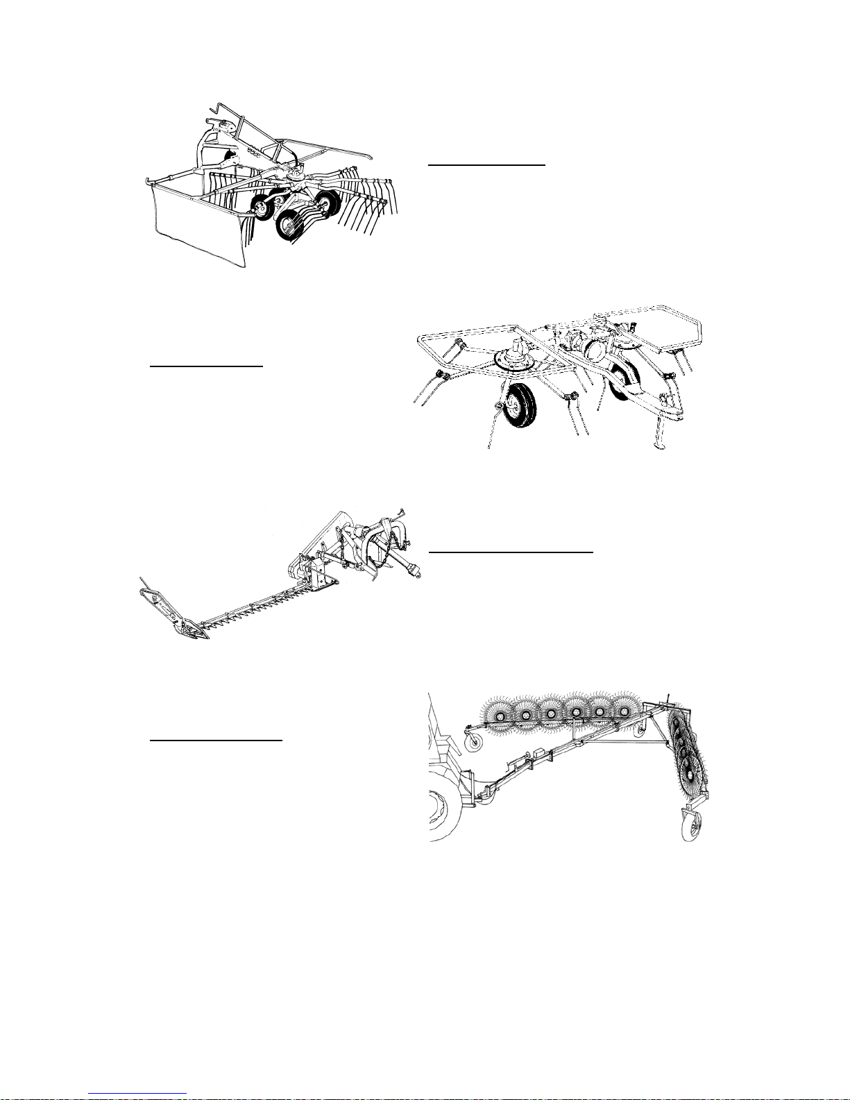
ROTARY RAKE
• 4 different models
• For tractors from 30 to 70 HP
• Working width from 340 to 695 cm.
HAY TEDDERS
• 6 different models (2, 4, 6 rotors)
• For tractors from 10 to 40 HP
• Working width from 310 to 730 cm.
SICKLE BAR MOWER
• 3 different models.
• For tractors from 10 to 15 HP.
FINGER WHEELS
• 8 different models (8-20 stars)
• For tractors from 30 to 80 HP
• Working width from 7.35 to 12.50 m.
 Loading...