

Page 1
PUN Installation,
Operation & Maintenance
Manual
P.O. Box 1380 • Portland ME, 04104-1380
Phone: (207) 878-0700 or (800) 743-1000
Email: [email protected]
Southworth Products PUN Manual
Southworth Products Corp.
Fax: (207) 797-4734
www.SouthworthProducts.com
July 2018
Page 2

Contents
1. Introduction ..................................................................................................4
1.1 Responsibilities of Owners and Users...................................................................4
2. Safety ............................................................................................................ 5
2.1 Safety Alert Symbols ............................................................................................... 5
2.2 Signal Words ............................................................................................................6
2.3 Safety Devices ..........................................................................................................6
3. Labeling ........................................................................................................ 6
3.1 Label Part Numbers & Quantity: .............................................................................6
3.2 Label Locations ........................................................................................................7
4. Installation....................................................................................................8
4.1 Preparation ............................................................................................................... 8
4.2 Positioning the Machine ..........................................................................................9
4.3 Hydraulic Connections ............................................................................................ 9
4.4 Electrical Connections ..........................................................................................10
4.5 Checking the Hydraulic System ........................................................................... 11
4.6 Testing ..................................................................................................................... 11
5. Operation....................................................................................................11
5.1 Operator Controls .................................................................................................. 12
5.2 Operational Sequence ........................................................................................... 12
5.3 Run Time Fault Sequence .....................................................................................13
5.4 Manual Mode ..........................................................................................................13
5.5 Operational Sequence Illustration ........................................................................14
6. Maintenance ............................................................................................... 15
6.1 Optional Support Stands ....................................................................................... 15
6.1.1. Support Stand Use Procedure.....................................................................15
6.2 Periodic Maintenance ............................................................................................ 16
6.2.1. Weekly Maintenance .....................................................................................16
Southworth Products PUN Manual2
Page 3

6.2.2. Monthly Maintenance ................................................................................... 17
6.2.3. Every six months or 500 hours .................................................................. 17
7. Troubleshooting ........................................................................................17
8. Adjustment & Replacement Procedures ................................................. 19
8.1 Aligning the Photo-Eyes ........................................................................................19
8.2 Proximity/Limit Switches: .....................................................................................20
8.3 Setting End of Travel for Tilt Down Function ......................................................20
8.4 Inspecting and Cleaning the Control Valve ......................................................... 20
8.5 Repacking a Cylinder.............................................................................................22
8.6 Replacing a Cylinder..............................................................................................23
9. Hydraulic System Information..................................................................25
9.1 Hydraulic Power Unit ............................................................................................. 25
9.2 Hydraulic Plumbing Schematic ............................................................................26
9.3 Hydraulic Arrangement .........................................................................................27
9.4 Hydraulic Connections .......................................................................................... 28
10. Electrical Information .............................................................................. 29
10.1 Control Panel ........................................................................................................29
10.2 Electrical Schematic ............................................................................................ 30
11. Warranty & Contact Information ............................................................31
Southworth ProductsPUN Manual PUN Manual3
Page 4

1. Introduction
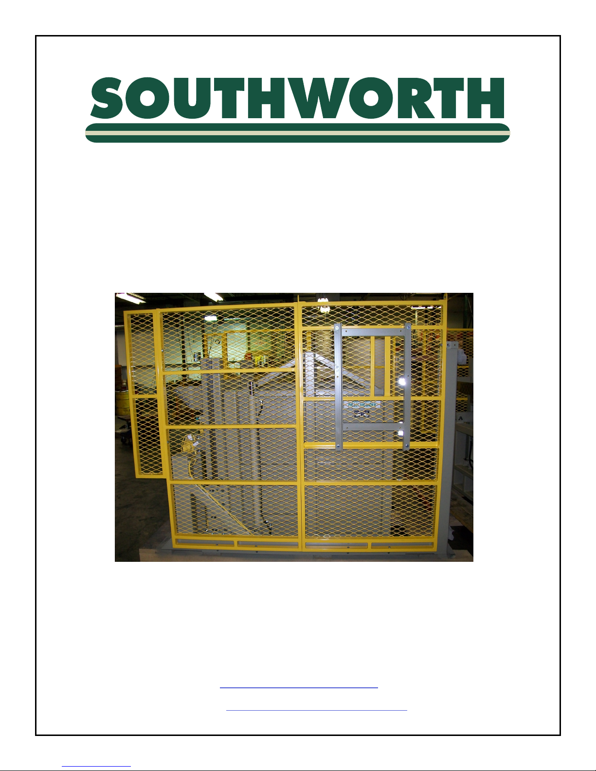
The Southworth Pallet Unloader (PUN) is designed to unload pallets. PUN units are
designed to tilt and lift materials, to be removed from the pallet individually, in a general
indoor industrial setting.
This manual is intended for PUN machines shipped during or
after February 2018 with control panels supplied by Southworth
Products. Please contact Southworth Products for information
about PUN machines shipped before February 2018 or with
control panels not as shown in the manual.
This manual contains instructions on the safe and proper installation, use, and
maintenance of the PUN unit. Be sure that this manual is available to the people who
install, use, or service the unit. Be sure that all personnel read this manual before they
install, use, or service the unit.
The instructions in this manual are not necessarily all-inclusive, as Southworth cannot
anticipate all conceivable or unique situations. In the interest of safety, please read this
whole manual carefully. Please understand the material in this manual before you install,
use, or service the PUN unit. If you have any questions about any of the instructions in this
manual, please contact Southworth Products Corp.
Southworth’s product warranty is shown on the rear cover of this manual. This instruction
manual is not intended to be or to create any other warranty, express or implied, including
any implied warranty of merchantability or tness for a particular purpose, all of which
are hereby expressly excluded. As set forth more specically in the product warranty,
Southworth’s obligation under that warranty is limited to the repair or replacement of
defective components, which shall be the buyer’s sole remedy, and Southworth shall not be
liable for any loss, injury, or damage to persons or property, nor for any direct, indirect, or
consequential damage of any kind resulting from the PUN unit.
1.1 Responsibilities of Owners and Users
Inspection and Maintenance – The device shall be inspected and maintained in proper
working order in accordance with Southworth’s owner’s manual.
Removal from Service – Any device not in safe operating condition such as, but not
limited to, excessive leakage, missing rollers, pins, or fasteners, any bent or cracked
structural members, cut or frayed electric, hydraulic, or pneumatic lines, damaged or
malfunctioning controls or safety devices, etc. shall be removed from service until it is
repaired to the original manufacturer’s standards.
Deection – It is the responsibility of the user/purchaser to advise the manufacturer where
deection may be critical to the application.
Repairs – All repairs shall be made by qualied personnel in conformance with
Southworth’s instructions.
Operators - Only trained personnel and authorized personnel shall be permitted to operate
the lift.
Southworth Products PUN Manual4
Page 5
Before Operation – Before using the device, the operator shall have:
• Read and/or had explained, and understood, the manufacturer’s operating instructions
and safety rules.
• Inspected the device for proper operation and condition. Any suspect item shall be
carefully examined and a determination made by a qualied person as to whether it
constitutes a hazard. All items not in conformance with Southworth’s specication shall
be corrected before further use of the equipment.
During Operation – The device shall only be used in accordance with this owner’s
manual.
• Do not overload.
• Ensure that all safety devices are operational and in place.
Modications or Alterations – Modications or alterations to any Southworth industrial
positioning equipment shall be made only with written permission from Southworth.
2. Safety
Before installing, operating, or servicing this machine read, understand, and follow all
safety instructions and warnings.
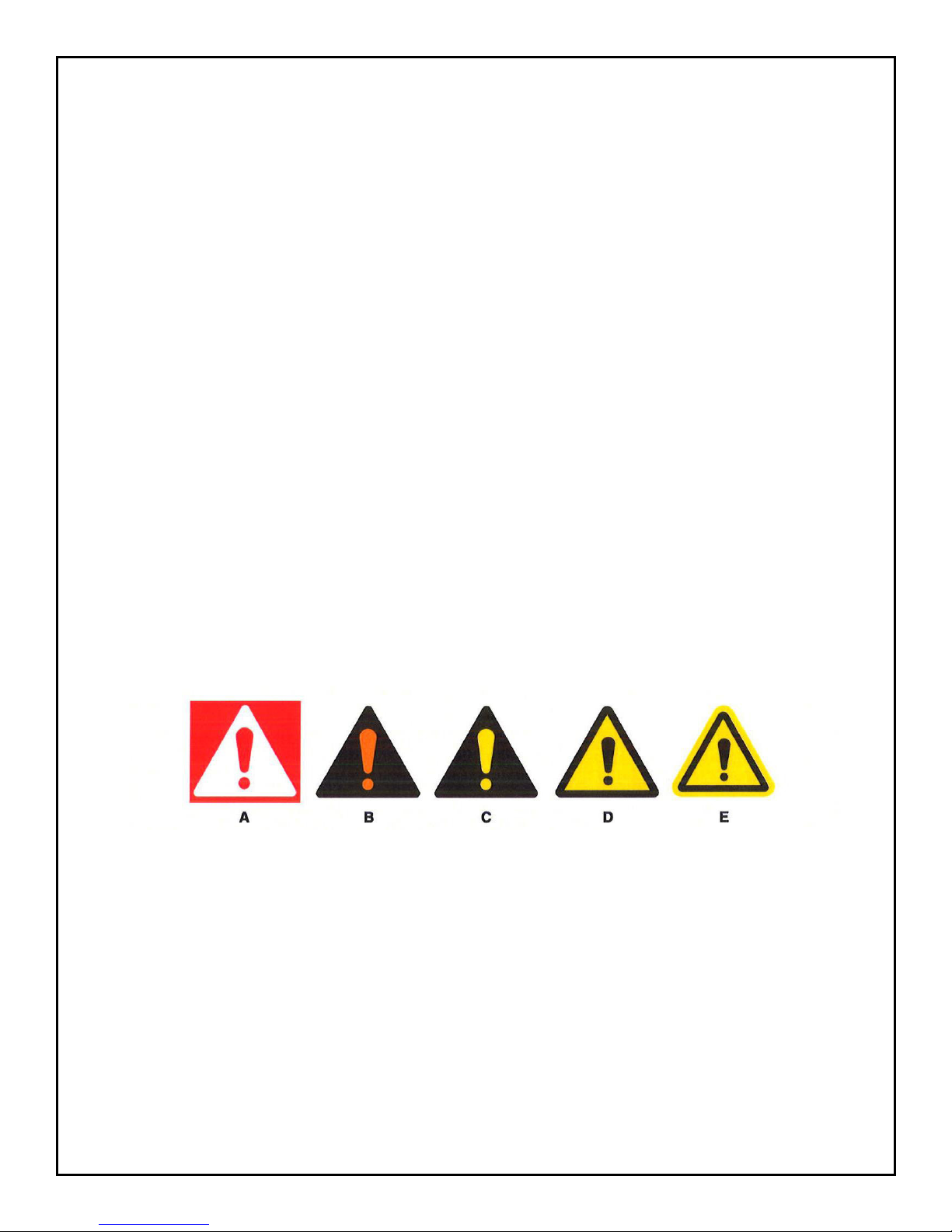
2.1 Safety Alert Symbols
A symbol that indicates a hazard. It is composed of an equilateral triangle surrounding an
exclamation mark. The safety alert symbol is only used on hazard alerting signs. It is not
used on safety notice and safety instructions signs.
A – For use with DANGER signal word; (safety white triangle, safety red exclamation mark,
safety red background)
B – For use with WARNING signal word; (safety black triangle, safety orange exclamation
mark)
C – For use with CAUTION signal word; (safety black triangle, safety yellow exclamation
mark)
D & E – For use with DANGER, WARNING, or CAUTION signal words; (D is a safety
yellow triangle with a safety black border and safety black exclamation mark; [E] is a safety
yellow triangle with a safety black exclamation mark and a safety yellow border around a
safety black band)
Southworth ProductsPUN Manual PUN Manual5
Page 6
2.2 Signal Words
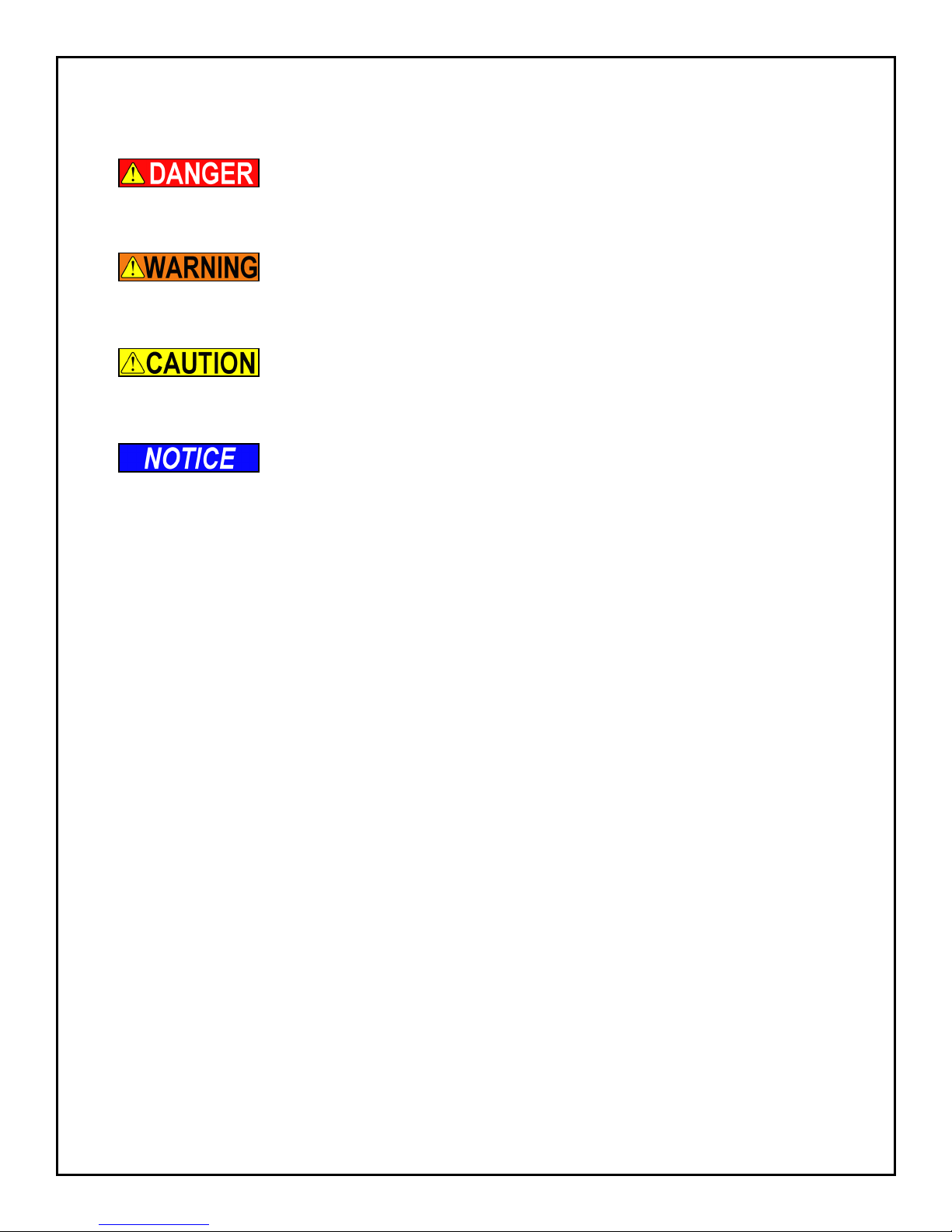
DANGER
WARNING
CAUTION
NOTICE
2.3 Safety Devices
Indicates a hazardous situation that, if not avoided, will result in
death or serious injury.
Indicates a hazardous situation that, if not avoided, could result
in death or serious injury.
Indicates a hazardous situation that, if not avoided, could result
in minor or moderate injury.
Indicates information considered important, but not hazardrelated (e.g., messages relating to property damage).
This machine is equipped with devices and features to protect the operator and nearby
personnel from severe injury or death. These features and devices shall be installed and
functioning correctly during operation.
Side Guarding – Protects operator and nearby personnel from moving parts.
Photo-eyes – Protects the operator and nearby personnel from entry into the load area
while machine is operating.
3. Labeling
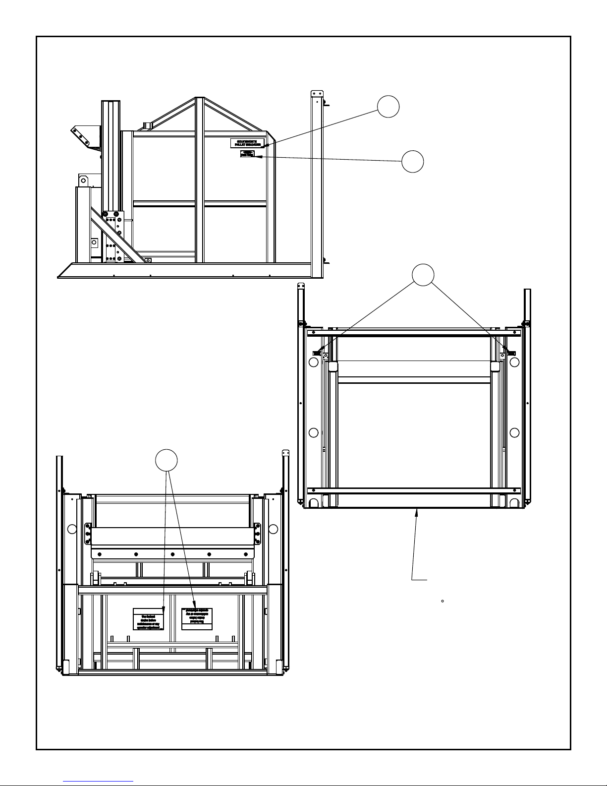
This machine has labeling to indicate potential hazards this machine may pose when
operating and/or maintaining the machine. All labels must be legible. If any label is missing,
damaged, or otherwise illegible contact the manufacturer for replacement labels.
3.1 Label Part Numbers & Quantity:
1. 2995290T - QTY. 2
2. 2995460T - QTY. 1
3. 2995191T - QTY. 3
4. 2995459T - QTY. 2
5. 2998592T - QTY. 2
Southworth Products PUN Manual6
Page 7
3.2 Label Locations
1
2
4
3
APPLY 2995191T TO
BOTTOM OF
ENCLOSURE. SHOULD BE
CENTERED AND WHEN
ENCLOSURE IS TILTED
90
Southworth ProductsPUN Manual PUN Manual7
Page 8
4. Installation
To avoid death or serious injury only trained and/or qualied
personnel shall perform any installation.
4.1 Preparation
Before installation – check for local codes and ordinances which may apply. It is your
responsibility to obtain any necessary permits. Read all of these installation instructions
carefully. Be sure to read and understand all of the warnings.
Select the location where the unit will be installed. Choose a location where the oor is rm,
at and level. As the unit operates, it is very important that the front edge (the load edge) of
the bucket touches the oor at the same time as the rest of the bottom plate touches.
If the middle or back edge of the bottom plate touches the oor
before the front edge of the bucket, the machine may try to raise
itself off the oor causing damage to the machine. This can
happen if the oor surface is not at.
Southworth Products PUN Manual8
Page 9

To avoid serious death or serious injury:
• If the unit is mounted on an unstable surface, it may tip over when in use. You
may be hurt, and the unit and load may be damaged.
• Protect the unit from rain or moisture. If the electrical parts in the power unit
get wet, workers may be hurt by electrical shock. The electrical parts may fail
if they are wet.
• The electric motor on the remote power unit can create sparks. Do not install
the power unit in an area where ammable gases may be present.
4. You will need these tools to install the unit:
• A lift truck that can lift the unit safely.
• Shims and appropriate lag bolts.
• A masonry drill and bit to drill the holes for the lag bolts.
• Extra hydraulic oil for ushing the hydraulic lines and relling the tank.
• Level.
4.2 Positioning the Machine
1. Remove the shipping material and unskid the unit. Move the unit into position,
supporting the base of the unit.
2. Level the machine using shims as necessary. Grout beneath the entire base from –
leave no gaps. Allow grout to fully cure before continuing.
3. Drill holes for lag bolts and install lag bolts.
Do not hang the unit from the bucket. This can damage the unit.
4. Check the movement of the bucket through its full range.
To avoid serious injury
• Pinch points may exist that may cause injury. Keep hands, feet, and loose
clothing away from moving parts.
4.3 Hydraulic Connections
1. Install the power unit. Run the hydraulic line between the power unit and the
PUN but do not make the connections yet. Be sure that the hydraulic line is
protected from passing trafc, and that it will not be damaged.
To avoid death or serious injury:
• Be sure that the hydraulic line will not be pinched by the unit as it raises or
lowers. If you allow the line to be pinched, the unit may not work properly. A
hose may break, the load enclosure may drop suddenly, and someone may be
hurt.
Southworth ProductsPUN Manual PUN Manual9
Page 10
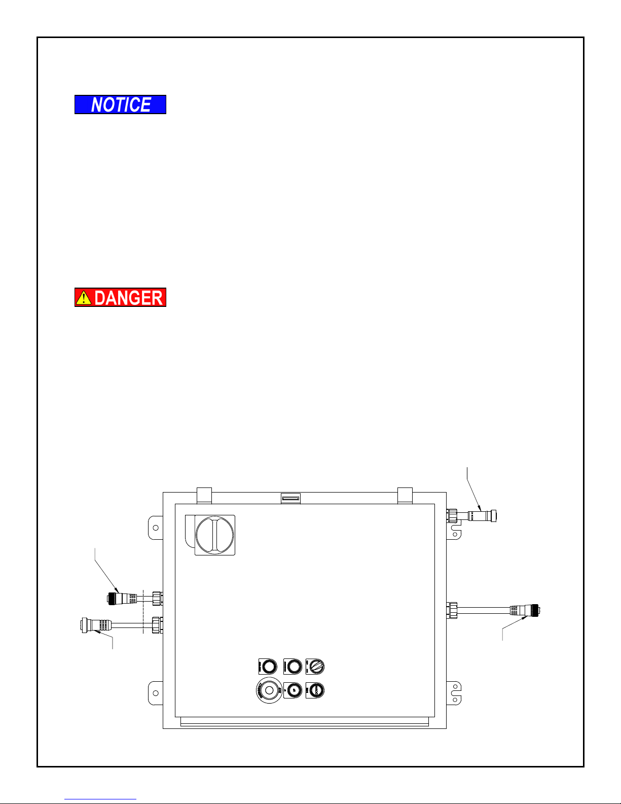
2. Before connecting the power unit, blow out the hydraulic lines with compressed
OF THE MACHINE
ON THE CYLINDER END
CONNECT TO MULTI-
PORT BASE LOCATED
CONNECT TO
JUNCTION BOX ON
HYDRAULIC POWER
air.
The hydraulic lines must be clear of any contamination or
damage to the hydraulic power unit will occur.
See Hydraulic Information section for specications, plumbing schematic and
location drawings:
1. Connect port A to the top of the tilting cylinders
2. Connect port B to the base of the tilting cylinders.
3. Connect port C to the base of the lifting cylinders.
4. Connect Vent Line from top of lifting cylinders to the tank.
4.4 Electrical Connections
To avoid death or serious injury:
• This unit requires three-phase 460V AC. This voltage can kill you. Don’t work
with the electrical parts unless you are a qualied electrician.
• The fuses or circuit breakers are designed to reduce any re hazard. Be sure
to install the fuses or circuit breakers.
CONNECT TO
MOTION ALARM
CONNECT TO THE
HYDRAULIC POWER
UNIT MOTOR
UNIT
Southworth Products PUN Manual10
Page 11
The power unit is designed for three-phase AC. If you connect
the power so the motor runs backwards, the bucket will not
move, and you may damage the pump. Do not operate the unit for
more than 2 or 3 seconds if you think the motor might be turning
backwards.
4.5 Checking the Hydraulic System
Check the level of the hydraulic uid in the system. With the bucket lowered completely,
the hydraulic uid can be checked by viewing the sight gauge on the reservoir of the power
unit.
4.6 Testing
1. Clear the area around the unit. Remove any materials which might get in the
way of the bucket as it raises or lowers. Be sure that the safety guards are in
place on both sides of the unit.
2. Warn others to stay away from the unit. Operate the unit through its full range
of travel. The bucket should rise smoothly with a quiet humming sound, and
lower smoothly and quietly. Raise and lower the bucket a few times to check the
operation.
3. As the bucket lowers, notice how the bottom of the enclosure meets the oor.
The front edge (load edge) of the enclosure should touch at the same time
as any other part of the enclosure. If any other part of the base of the bucket
touches before the front edge, the oor is not at. Insert shims above the low
spots on the oor, so that the base is at and level.
4. As a nal step, clean up all spilled hydraulic uid. Spilled hydraulic oil is slippery,
and may present a re hazard. If you clean up any spilled uid, you will be able
to tell right away if the unit begins to leak.
5. Operation
If another part of the bucket touches the oor before the front
edge, the machine may not stop automatically at the correct
moment. This may cause the machine to try to lift itself off of the
oor.
If the “Tilt Down” proximity switch is out of adjustment, the
machine may continue to run when it should be stopped. This
may cause the machine to try to lift itself off of the oor. This
could cause damage to the unit.
To avoid death or serious injury:
• Only trained and/or qualied personnel may operate the machine.
• Crush, pinch, and shear points exist; keep hands, feet, and loose clothing
away from moving parts.
Southworth ProductsPUN Manual PUN Manual11
Page 12
To avoid death or serious injury:
• Ensure all safety devices and guarding are installed and operating correctly.
• Verify that area in and around the machine are clear of debris and/or personnel
before operating the machine.
Load shall not exceed the machines rated capacity. Overloading
the machine can cause damage to the machine.
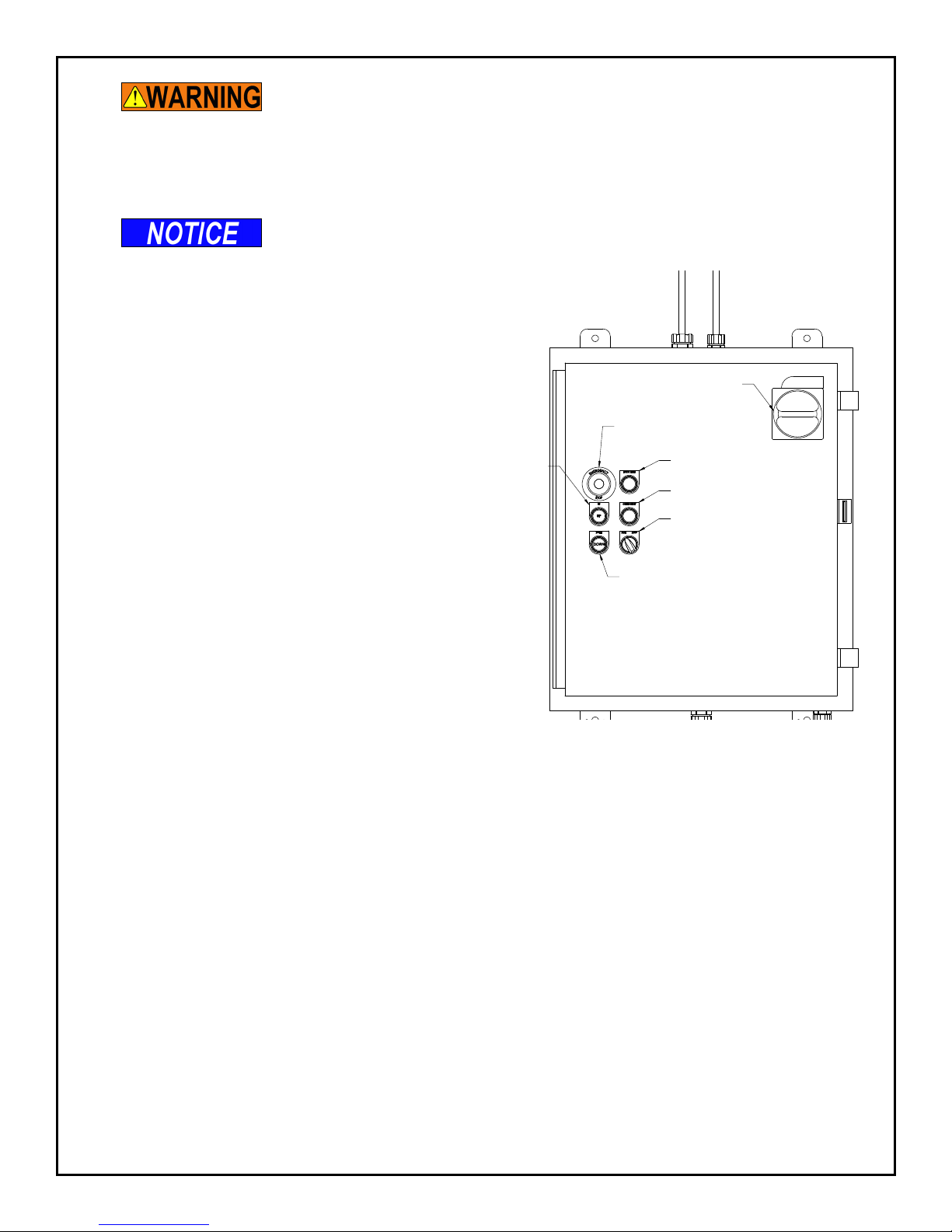
5.1 Operator Controls
• Main disconnect switch – Controls main
power supply to the control panel.
• Emergency Stop – Used to stop the
machine in the event of an emergency.
• E-STOP RESET – Used to reset the
controls system after the Emergency
Stop button has been pressed.
UP
BUTTON
MAIN DISCONNECT SWITCH
EMERGENCY
STOP (E-STOP)
BUTTON
• GUARD RESET – Used to reset the
control system after the photo eyes
detect an obstruction.
DOWN BUTTON
• UP – Used to start the tilting and lifting
sequence.
• DOWN – Used to start the lowering
sequence.
5.2 Operational Sequence
With the machine turned off and the bucket in the fully lowered position.
1. Turn the main disconnect switch to the ON position. The red E-STOP light should
turn on.
E-STOP RESET
GUARD RESET
MAN/AUTO MODE SELECTOR
2. Pull the EMERGENCY STOP button and press the E-STOP RESET button. The
red E-STOP light should turn off, the green E-STOP RESET light should turn on,
and the GUARD RESET light should turn on.
3. Turn the selector switch to the AUTO position.
4. Press the GUARD RESET button. If the photoeyes do not detect an obstruction
the GUARD RESET light will turn off and the machine will be ready to operate.
5. Move load into the bucket. Verify that load does not exceed the machine rated
capacity. Loading will disrupt the photoeyes causing the GUARD RESET light to
turn on.
6. Press the GUARD RESET button. If the photoeyes do not detect an obstruction
the GUARD RESET light will turn off and the machine will be ready to operate.
Southworth Products PUN Manual12
Page 13

7. Press and hold the UP button for one second. The motion alarm with ash and
beep. Release the UP button. The bucket will tilt up until the Tilt Up proximity
switch is reached.
8. To lift the bucket press and hold the UP button until enclosure reaches the
desired height. The UP button must be held for three seconds before the
machine begins to move. The motion alarm will ash and beep. To stop the
enclosure release the UP button. This process can be repeated until the Lift Up
proximity switch is reached.
9. To return the bucket to the full down position press the DOWN button. The
DOWN button must be held for three seconds before the enclosure will begin to
move. The motion alarm will ash and beep. After the enclosure begins to move
the DOWN button can be released. The machine will tilt back until the Tilt Down
proximity switch is reached then lower until the Lift Down proximity switch is
reached.
Note: If the photoeyes detect an obstruction the machine will stop and the GUARD RESET
light will turn on. The machine will not operate again until the obstruction is cleared and the
GUARD RESET button has been pressed.
If the EMERGENCY STOP button has been pressed. Steps 2 & 3 must be performed to
resume operation.
5.3 Run Time Fault Sequence
If the lift lowering motion takes longer than 25 seconds, or the other motions take longer
than 15 seconds, a Run Time Fault has occurred. The fault could be caused by a tripped
overload relay, blown fuses, damaged hydraulic lines, faulty valve, damaged wiring, or a
damaged or faulty proximity switch.
When a Run Time Fault occurs the machine will stop and the GUARD RESET light will turn
on. Trained and/or qualied personnel should examine the machine for the cause of the
problem before it is return to operation.
To return the machine to operation:
1. Ensure the cause of the Run Time Fault has been corrected.
2. Turn the selector switch to the MANUAL position and press the GUARD RESET
button for ve seconds. The GUARD RESET light should turn off and operation
can resume.
5.4 Manual Mode
There are two uses of MANUAL mode:
1. To stop and correct and automatic motion started in error. Turning the selector
switch to MANUAL position will stop all automatic motion. The machine can be
manually operated with the UP and DOWN buttons to return the machine to a
particular starting position.
Southworth ProductsPUN Manual PUN Manual13
Page 14
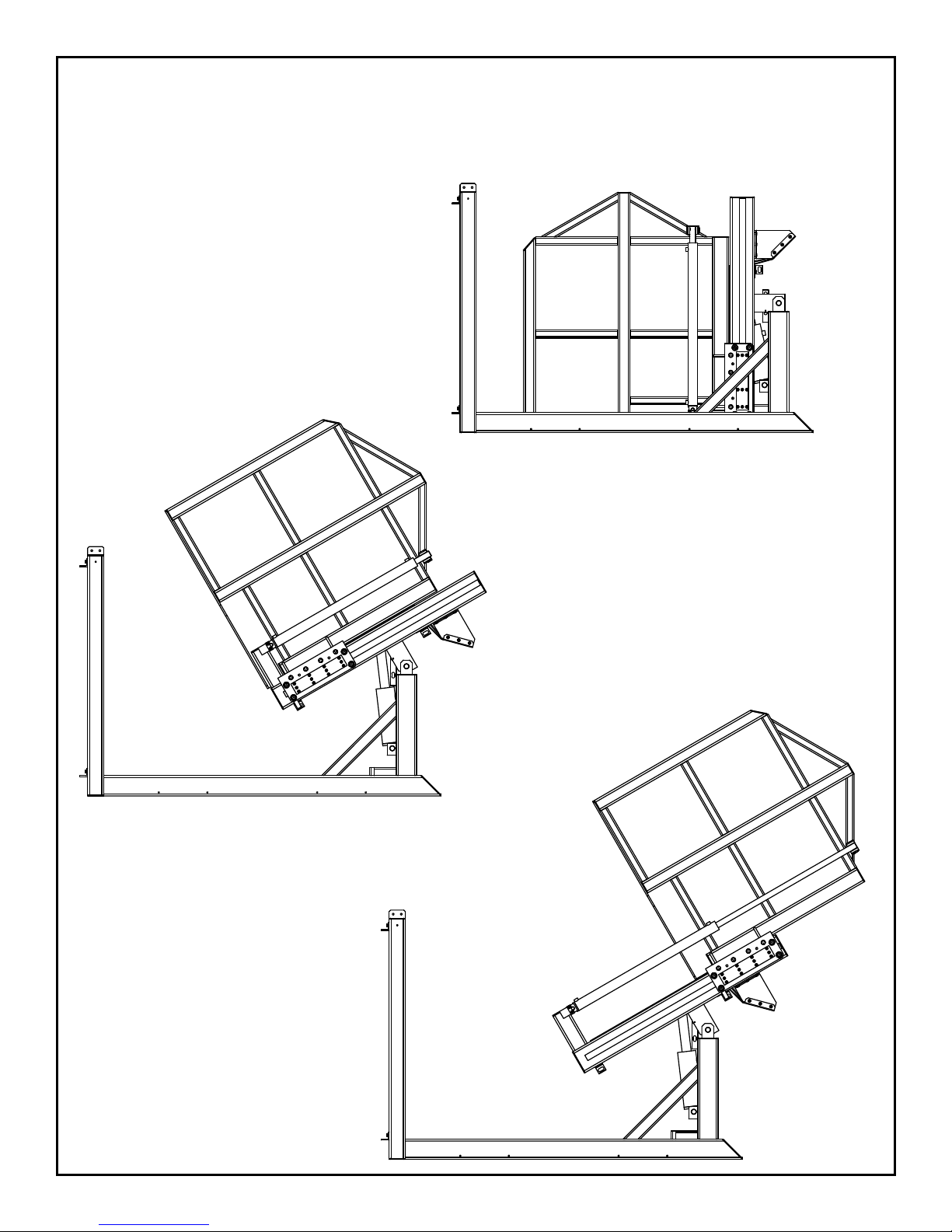
2. To test and diagnose problems with the machine by using the UP and DOWN
buttons
5.5 Operational Sequence Illustration
FULLY LOWERED POSITION
FULL TILT & FULL
RAISED POSITION
TILTED TO TILT UP
PROXIMITY SWITCH
Southworth Products PUN Manual14
Page 15

6. Maintenance
To avoid death or serious injury:
• Only trained and/or qualied personnel shall perform maintenance or repair.
• All maintenance shall be perform with the bucket in the fully lowered position.
• Ensure pressure has been released from the hydraulic system before
performing any maintenance. Pressurized uid can penetrate skin and cause
death or severe injury.
• No adjustment to the hydraulic relief valve shall be made. Changing the relief
valve setting may cause the machine to act in an unpredictable manner.
• All labeling shall be legible. If labels are missing, damaged, or otherwise
illegible contact the manufacturer for replacement labels.
It is important to immobilize parts of the tilt and dump mechanisms before you service the
unit. Please follow all of these steps whenever you work on the unit:
1. Lower the bucket completely to the loading position. The cylinders and other
parts can be removed safely from either the tilt or dump mechanisms when the
bucket is completely lowered. Normally, you should never need to work under
the bucket. Always stay clear of the space under this enclosure.
2. Turn off the electrical power at the main disconnect or circuit breaker. Follow
standard lock-out, tag-out procedures. Do not let anyone else use the controls
on the unit.
3. When you are nished, operate the machine, without a load, through at least
one cycle. Be sure that it is operating smoothly and properly before returning it to
regular operation.
6.1 Optional Support Stands
The PUN Support Stands shall not be used for hydraulic, electrical, or mechanical
maintenance.
Read and understand the Support Stand Use Procedure before
using the support stands. Failure to follow the use procedure
may result in damage to the machine.
6.1.1. Support Stand Use Procedure
To remove the machine from service:
1. Using the control pushbutton raise the tilt frame to the highest position.
2. Turn the main disconnect switch to the OFF position. Follow Lock Out Tag Out
procedures.
3. Set the support stands at the highest extension pin position.
Southworth ProductsPUN Manual PUN Manual15
Page 16

Both support stands must be used. Never use only one stand
under the tilt frame.
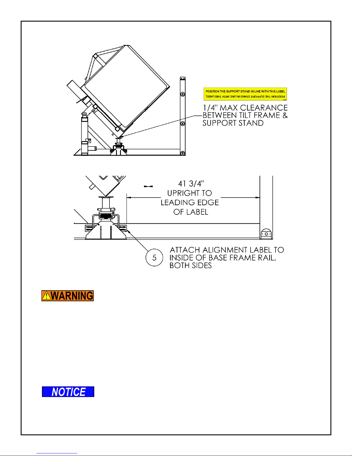
4. Position each support in the load area as indicated by the alignment label on the
inside of the base frame rail. See Support Stand Placement drawing.
Note: If not present attach alignment label (2998592T) to base frame rails
according to Support Stand Placement drawing.
The load area must be clear of debris. Never have anything under the support
stands when in use.
5. After all personnel are clear of the load area remove the lock out and turn the
main disconnect switch to the ON position.
6. Using the control pushbutton lower the tilt frame until it is within 1/4” of the
stands.
If the frame starts to contact the support stands the machine
motion must be stopped by the operator. Do not over power the
tilt frame on to the support stands. This may damage the machine
and over stress the oor anchors.
7. Turn the main disconnect switch to the OFF position. Follow Lock Out Tag Out
procedures.
8. It is now safe to access the load area.
To return the machine to regular service:
1. Remove the lock out and turn the Main Disconnect switch to the ON position.
2. Using the control pushbutton raise the tilt frame to the highest position.
3. Turn the main disconnect switch to the OFF position. Follow Lock Out Tag Out
procedures.
4. Remove the support stands from the load area.
5. After personnel are clear of the load area remove the lock out and turn the Main
Disconnect switch to the ON position.
6. Using the control pushbutton lower the tilt frame to fully lowered position.
6.2 Periodic Maintenance
6.2.1. Weekly Maintenance
• On the tilt mechanism and dump mechanism, check all of the hydraulic ttings and
hoses, and repair as necessary. Sometimes the ttings can be worked loose by the
vibrations in the hydraulic system.
Southworth Products PUN Manual16
Page 17

To avoid death or serious injury:
• If a hydraulic tting becomes loose, or if a hydraulic hose breaks, the
hydraulic uid may escape from the system under pressure. If the bucket is
elevated when this happens, this can cause it to drop. Someone may be hurt,
or the unit or load may be damaged. Be sure all hydraulic ttings are free of
leaks.
• Check the operation of the three photo eyes on the entry side of the machine. With the
bucket in the fully lowered position, break the beam of each photo eye. Here are the test
conditions for the photo eyes:
• Beam unbroken - LED on photoeye is lit.
• Beam is broken - LED on photoeye is out.
• When you break any beam, this should trigger a stop condition which requires the
controls on the machine to be reset to return to “Ready” condition. The reectors for the
photo eyes should be replaced if they are cracked or otherwise damaged.
• Check and tighten all hardware.
6.2.2. Monthly Maintenance
• On the tilt and dump mechanisms, inspect the main pivot pins and bushings and the
cylinder clevis pins and bushings for signs of wear.
To avoid death or serious injury:
• If you are going to repair the main pivot pins and bushings on either the tilt or
dump mechanisms, you must return the bucket to the loading position.
• Check the level and appearance of the hydraulic uid. When the bucket is fully lowered,
the oil should be at the correct level as viewed through the sight glass on the reservoir.
Add oil as necessary. Change the oil and lter if the oil has darkened, or feels gritty or
sticky.
6.2.3. Every six months or 500 hours
• The hydraulic system includes a replaceable oil lter. Replace this lter as part of your
routine maintenance. Inspect the oil, and replace it if necessary. If the oil is changed,
thoroughly clean the reservoir, including the suction strainer.
• Be sure all of the warning labels are in position and legible. See Labeling Section. The
warning labels are intended to protect your workers. If the labels are missing, or if they
have been painted over, replace them.
7. Troubleshooting
To avoid death or serious injury:
• All maintenance, repair, and diagnosis shall be performed by trained and/or
qualied personnel only.
Southworth ProductsPUN Manual PUN Manual17
Page 18
• Follow steps in Maintenance section to make the machine safe to inspect and
maintain.
To avoid death or serious injury:
• All maintenance and repair shall be performed with the bucket in the fully
lowered position.
• Ensure pressure has been released from the hydraulic system before
performing any maintenance. Pressurized uid can penetrate skin and cause
death or severe injury.
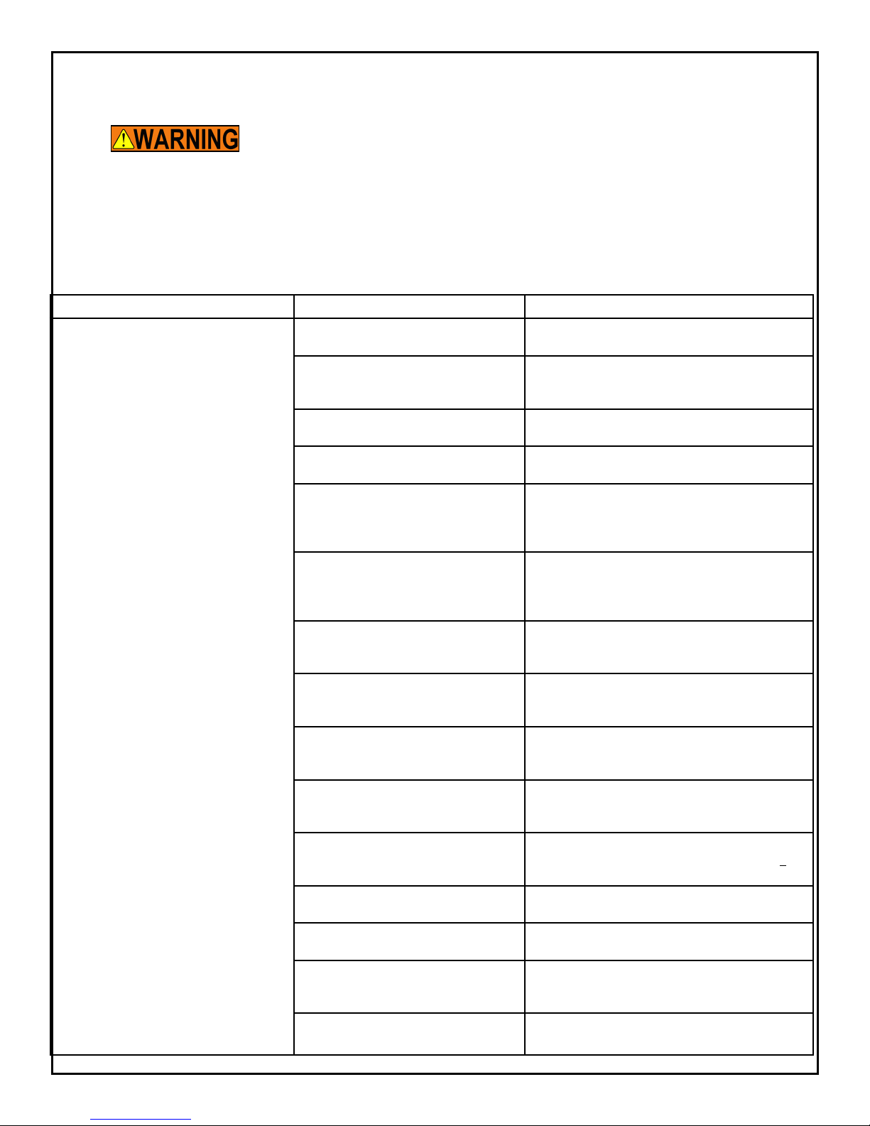
Symptom Possible Cause Remedy
Neither lift mechanism is working: CAUTION!
If the tilt function does not begin right away,
don’t continue to operate the “up” control for
more than 2 or 3 seconds. You may damage
the pump.
The power for the unit may be switched
off.
One of the fuses or circuit breakers may
have opened.
The Emergency Stop switch may have
been pressed.
One of the protective light beams at the
front of the unit may be blocked.
There may be a problem with one of the
photo eyes.
The motor for the pump may have
stopped. The motor controls have built-in
over current protection in case of an
overload.
The motor may be running backwards. If this is happening, the pressure valve will indicate
The motor may be “single phasing”. This causes the motor to hum, but not turn. Check for
The motor may be running backwards. If this is happening, the pressure valve will indicate
The motor may be “single phasing” This causes the motor to hum, but not turn. Check for
The voltage to the motor may be too low. Check the voltage at the starter when the motor is
The level of the hydraulic oil may be low. When the unit is lowered completely, check the oil
The ller/breather cap on the hydraulic
tank may be plugged.
There may be a vacuum leak in the suction line. (This could cause cavitation and
loss of suction in the pump.)
The coupling between the pump and motor may be missing.
Turn on the “Main Disconnect” switch.
Replace the fuse, or reset the circuit breaker. If
the condition repeats, determine the cause of the
problem.
Reset the Emergency Stop switch, and reset the
control system.
Be sure the space in front of the unit is clear.
Check the alignment of each photo eye and its reector. When the eye can “see” the reector, the LED on
the photo eye should light. Check the power supply to
the photo eye. Replace the part if it is faulty.
The protective circuit will reset after it has cooled.
Look for anything which may be preventing the motor
from turning.
zero pressure even though the motor is running.
Reverse any two electrical leads on the motor.
a break in one lead to the three-phase motor. Check
the motor wiring and line fuses.
zero pressure even though the motor is running.
Reverse any two electrical leads on the motor.
a break in one lead to the three-phase motor. Check
the wiring and line fuses.
under load. The supply voltage should be within +
10% of the rating.
level by viewing the reservoir sight gauge.
Remove the cap and clean the bafes inside it.
Check the suction line hose and ttings. CAUTION!
Do not allow cavitation to continue -- this may damage the pump.
Remove the pump as described in this section.
Check to see that the coupling is in place.
Southworth Products PUN Manual18
Page 19
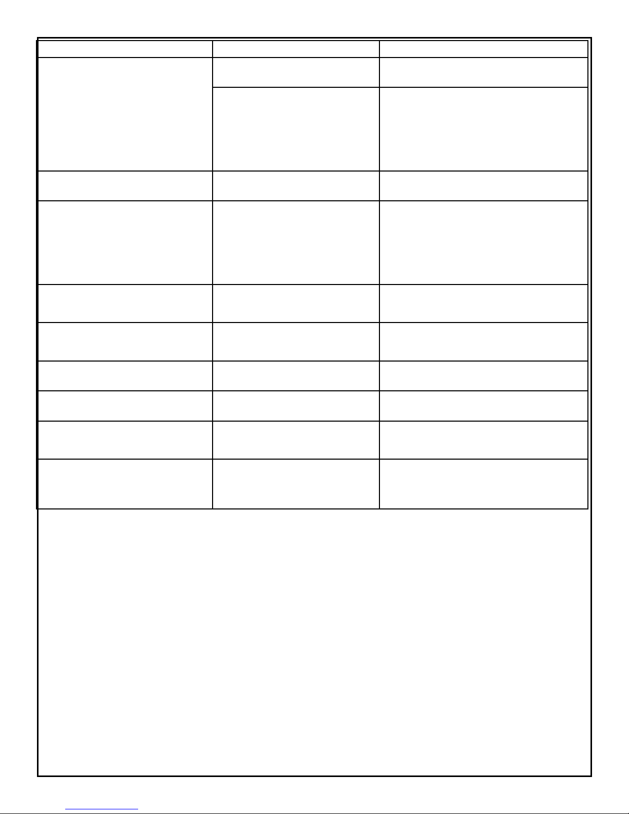
Symptom Possible Cause Remedy
The tilt mechanism will not raise. The up-proximity switch for the tilt lift func-
tion may be out of adjustment.
Check the adjustment of the switch. (See the section
on “Adjustment and Alignment”.)
The “up” side of the control valve for this
function may not be working.
The tilt mechanism raises slowly. The counter-balance valve in this circuit
may be plugged.
The tilt mechanism does not lower. Warning!
Before working under any raised parts of the
unit, support the body of the unit using a set
of strong supports.
When the load enclosure is lowered, the
center or rear touches the oor before the
front edge (load edge).
The pump motor continues to run after the
front edge (load edge) of the load enclosure
touches the oor.
The “Tilt Down” part of the cycle begins
prematurely.
The “down” side of the control valve for
this part of the system may not be working.
The oor is not at. Insert shims above the low spots in the oor. The
The proximity switch for the “Tilt Down”
function may be out of adjustment.
The tilt frame may be hitting the stop pads
at the upper limit of travel too hard.
The “up” side of the valve must be energized and
fully open. Check the solenoid on the “up” side of the
valve with a voltmeter. Check for a problem with the
wiring to the control valve. The valve must be clean
and free to operate. Release the pressure from the
system and clean the valve. (See the section on
“Inspecting and Cleaning a Control Valve”.)
Release the pressure from the system and clean the
valve.
The “down” side of the valve must be energized and
fully open. Check the solenoid on the “down” side of
the valve with a voltmeter. Check for a problem with
the wiring to the control valve. The valve must be
clean and free to operate. Release the pressure from
the system and clean the valve. (See the section on
“Inspecting and Cleaning a Control Valve”.)
base frame of the machine must be at and level.
Adjust the position of the target for this switch.
Adjust the position of the target for the “Tilt Up”
proximity switch.
The dump mechanism will not raise. The up-proximity switch for the dump lift
function may be out of adjustment.
The pump motor continues to run after the
load enclosure has reached the upper limit of
the dump travel.
At the end of the cycle, the load enclosure
drops onto the base frame.
The “Lift Up” proximity switch may be out
of adjustment.
The proximity switch for the “Dump Down”
function may be set too high. When the
motor is shut off, this allows the load
enclosure to drop.
8. Adjustment & Replacement Procedures
8.1 Aligning the Photo-Eyes
1. The photo-eyes are part of a system which protects the operators from moving
parts which are potentially dangerous. If an operator moves close to the loading
end of the machine, and breaks any of the 3 light beams, the unit will stop
immediately. The unit will not run again until the control system has been reset.
Each eye sends a light beam to a matching reector. The beam is then returned
to the light sensor.
2. When the machine is turned on, check the LED indicator on the side of the
photo-eye. If the photo eye is properly aligned and is not blocked, with the beam
returning from the reector, the LED will light. If the photo-eye cannot see the
reector, or the beam is blocked, the LED will be out. If necessary, move the
reector until the LED lights.
Check the adjustment of the switch. (See the section
on “Adjustment and Alignment”.)
Check the adjustment of the switch. (See the section
of “Adjustment and Alignment”.)
Check the adjustment of the switch. (See the section
on “Adjustment and Alignment”.)
Southworth ProductsPUN Manual PUN Manual19
Page 20

3. If the LED will not light, yet the reector seems to be aligned, check that the
photo eye is receiving power.
8.2 Proximity/Limit Switches:
1. On this machine, proximity switches are used as limit switches. Each switch has
two parts a sensor and a target. Each switch is a “normally open” type.
2. The nominal distance between each sensor and its target is 3/16”. If the sensor
can see the target, the LED on the side of the sensor will light. If necessary,
change the alignment of the target or sensor until the LED lights.
3. If the LED will not light, yet the target seems to be aligned, check that the
proximity switch is receiving power.
8.3 Setting End of Travel for Tilt Down Function
If any part of the base plate contacts the oor, except for the front
lip, you must shim the base of the machine.
If the motor continues to run after the front of the bucket touches
the oor, the unit may try to lift itself off of the oor. This can
damage the machine. To correct this problem, move the target so
that it activates the switch sooner.
Set the unit so that the loading edge of the bucket is touching the oor.
Position this switch so that the bucket stops lowering when the front lip of the bucket just
contacts the oor. When the bucket reaches this limit, the switch should send a signal to
stop the motor on the hydraulic power unit.
8.4 Setting End of Travel for Tilt Up Function
If the frame of the bucket is allowed to hit the stop pads with too
much force, it will have an erratic motion. It may even bounce off
of the pads and begin the Tilt Down part of the cycle by itself.
Set this switch so that the tilt function of the bucket stops just as the frame of the bucket
hits the stop pads, or just a moment before. When the bucket reaches this limit, the switch
should send a signal to stop the motor on the hydraulic power unit. A clearance of 1/8” from
the pads is acceptable.
8.5 Inspecting and Cleaning the Control Valve
1. Check that the valve is receiving the correct control voltage. When the valve is
supposed to be energized, the solenoid should receive 24V DC.
2. Check the continuity through the solenoid coil. With the power off, check the
resistance through the coil using an Ohmmeter. There should be a low resistance
(a few Ohms). If the meter shows no resistance, the coil may be shorted.
Substitute a coil which is known to be good. If the meter shows an innitely high
resistance, the coil should be replaced.
Southworth Products PUN Manual20
Page 21

3. Each valve used on this machine is designed with a solenoid coil which can be
changed without removing the valve or spilling any hydraulic uid. To change the
solenoid:
• Disconnect the wire leads to the solenoid.
• Loosen the knurled nut at the top of the solenoid, and remove the nut and
O-ring.
• Slide the solenoid off of the core tube.
4. To clean the parts on the valve spool, you must remove it from the valve
body. De-pressurize the hydraulic system by lowering both lifting mechanisms
completely. Be sure to turn off the power to the machine.
5. Unscrew the core tube. Remove the valve plunger and inspect it for dirt or metal
chips which could block the valve action. Clean the valve plunger as required,
then blow it clean with compressed air. Before reassembly, verify that the inside
of the valve body is clean and free of debris. Depress the plunger by hand
several times to be sure it moves freely.
6. To reassemble, reverse the steps listed above. The nut which holds the solenoid
should be nger-tight only!
8.6 Removing a Cylinder
To avoid death or serious injury:
• All repair or maintenance shall be performed with the bucket in the fully
lowered position. See the Maintenance section before beginning any work.
• Hydraulic Cylinders are heavy. Falling cylinders can cause serious injury.
This section will tell you how to remove a cylinder from the tilt mechanism or the dump
mechanism. Two cylinders are used on each mechanism. Both types of cylinders are
double-acting, and both have the same bore diameter. The following procedure will apply
to both cylinder types.
Before beginning this procedure, please read and understand this entire section.
1. Before you remove a cylinder, be sure that you have these items on hand:
• Replacement cylinder or cylinder packing kit.
• A supply of new hydraulic oil. Contaminated oil may damage the new
packing.
• Containers to catch the used oil.
• A clean place to work which will not be damaged if you spill some oil
(especially if repacking the existing cylinder).
2. Lower the bucket completely to the loading position (as discussed earlier).
3. Turn off the electrical power at the main disconnect or circuit breaker. Follow
Southworth ProductsPUN Manual PUN Manual21
Page 22
standard lock-out/tag-out procedures.
4. Disconnect the hydraulic supply line to the bottom end of the cylinder. Place the
free end into a container to collect the used oil.
5. Repeat the same procedure for the hydraulic supply line to the top end of the
cylinder.
6. At the top end of the rod remove the “keeper” from the upper cylinder clevis and
drive out the upper clevis pin. Repeat the same procedure to remove the lower
cylinder clevis pin.
7. Push the rod back into the cylinder to drive the hydraulic uid out through the
hose and into the container. You may use air pressure at the hydraulic port to do
this.
8. Now the cylinder can be removed for repacking
or replacement.
8.7 Repacking a Cylinder
Repacking the cylinders requires special training
and tools. If you are not familiar with repacking
procedures, this work should be left to a qualied
hydraulic repair shop.
During reassembly, it is very important to keep all
of the parts free of dirt, dust, metal chips, water,
and other contamination. Most of the problems with
hydraulic systems are caused by contamination in
the oil.
1. Begin by removing the cylinder as described in the
last section.
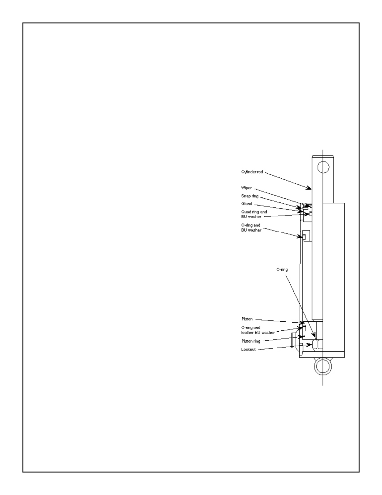
2. The image shows the parts inside a cylinder. Secure
the cylinder in a vise so that it cannot turn. Clear the
work area so that you can lay the parts on a clean
surface.
3. At the upper end of the cylinder, remove the snap
ring. Pull the rod to within 3 inches of full extension.
Compress the ring and, at the same time, pull
outward on the rod. This will pull the gland out of the
cylinder.
4. Pull the rod and piston all of the way out of the cylinder. This assembly is heavy! Be
careful not to drop it as it comes free.
5. Remove the piston from the cylinder rod. (Be careful to protect the cylinder rod as you
do this. Any burrs on the rod could damage the packing.) Note the position of the piston
ring and remove it. Remove the leather BU washer and larger O-ring from the piston.
Southworth Products PUN Manual22
Page 23

Remove the smaller O-ring which ts around the cylinder rod.
6. Remove the gland from the cylinder rod by sliding it off of the end which holds the
piston. Notice how the wiper ring sits in the gland. Note the positions of the quad ring
and BU washer. Remove the wiper ring, quad ring and BU washer from the gland.
7. Clean all of the surfaces on the gland. Install a new quad ring and BU washer. Install a
new wiper ring in the correct orientation. Coat the inner diameter of the gland with light
grease and replace it on the rod.
Be careful not to install the wiper backwards.
8. Clean the piston surfaces. Install a new larger O-ring and leather BU washer on the
piston. Install a new piston ring. Install a new smaller O-ring. Attach the piston to the
rod and tighten the large nut.
9. Clean the bore of the cylinder tube thoroughly. Inspect the bore of the tube for
scratches which run up and down, along the length of the cylinder. If you do see any
scratches, hone the inner surface of the cylinder. Be sure to clean the tube thoroughly
after you do this.
10. Lubricate the inner diameter of the cylinder tube with a light coating of hydraulic oil.
Carefully insert the piston and rod back into the cylinder. Be very careful not to damage
the piston ring, O-ring or BU washer as you do this. It may be helpful to tip the rod
assembly and twist it as you slide it into the cylinder. Once the piston is inside the
cylinder, it should slide easily.
11. Slide the gland assembly into the cylinder. Rotate the gland so the port lines up with
the hole in the cylinder tube. Install a new snap ring. Compress the snap ring, tap the
gland into place, then relax the snap ring. Be sure that the snap ring is in place in the
groove.
12. Install the cylinder in the unit as described below.
8.8 Replacing a Cylinder
Before beginning this procedure, please read and understand this entire section.
1. Before beginning, read steps 2 through 4 in the procedure “Removing a Cylinder”
listed above.
2. Place the cylinder near the point where it will t into the mechanism. Be sure the
cylinder ports are oriented correctly.
3. Align the lower cylinder with each lower cylinder clevis and insert the lower
cylinder clevis pin. Be careful! The cylinder is heavy! Replace the “keeper” and
secure it with the button-head cap screws (supplied). Repeat the same procedure
to replace and secure the clevis pin for the upper cylinder.
Southworth ProductsPUN Manual PUN Manual23
Page 24

4. Attach the lower and upper hydraulic supply lines.
5. Be sure everyone is clear of the equipment. Turn on the power and test the
unit. Run the mechanism through a couple of cycles to completely purge any air
trapped in the hydraulic lines.
8.9 Ordering Replacement Parts
Southworth has carefully chosen the components in your lift to be the best available for the
purpose. Replacement parts should be identical to the original equipment. Southworth will
not be responsible for equipment failures resulting from the use of incorrect replacement
parts or from unauthorized modications of the machine.
Southworth will gladly supply you with replacement parts for your Southworth lift. With your
order, please include the model number and the serial number of the lift. You can nd these
numbers on the name plate, which is located on the crossbar at the base of the cylinder(s).
When you are ordering parts for a cylinder, also include the cylinder number. This is
stamped on the base of the cylinder housing.
To order replacement parts, please call the Parts Department. See Warranty & Contact
Information section.
• Parts are shipped subject to the following terms:
• FOB factory
• Returns only with the approval of our parts department.
• Payment net 30 days (except parts covered by warranty).
• Freight collect (except parts covered by warranty).
• The warranty for repair parts is 30 days from date of shipment.
Parts replaced under warranty are on a “charge-credit” basis. We will invoice you when we
ship the replacement part, then credit you when you return the worn or damaged part, and
we verify that it is covered by our warranty. Labor is not covered under warranty for Parts
orders.
Southworth Products PUN Manual24
Page 25

9. Hydraulic System Information
9.1 Hydraulic Power Unit
HYDRAULIC POWER UNIT SPECIFICATIONS
MOTOR: Baldor: 5HP, 1750 RPM 208/230 - 460V / 3 / 60, 184TC wired for 460.
PUMP: Parker gear pump: 0.61 CUIN / Rev with pump adapter and ex coupling for
1750 PSI operation.
RESERVOIR: 15 gallon with suction strainer, return lter and drip pan.
VALVE MANIFOLD: Parker 2-station parallel manifold with system relief valve, dual
counter balance valves and pump unloading valve.
PRESS GAUGE: 0 - 2,000 PSI
RECOMMENDED FLUID: If the lift will be used at normal ambient temperatures, the
machine is supplied the unit with Conoco AW 32 oil. This may be replaced by any other
good quality oil with 150 SSU at 100° F and rust and oxidation inhibitors and anti-wear
properties. If the lift will be used at ambient temperatures below 0°F, use aircraft hydraulic
oil. Use Type 15 aircraft hydraulic oil.
The following are
equivalent to Conoco AW
32:
Type Manufacturer
DTE 24 EXXON/MOBIL
NUTO H32 EXXON/MOBIL
AMOCO AW32 CHEVRON (AMOCO CO.)
AW32 CITGO
Debris in the hydraulic system can damage the hydraulic pump.
Make sure tank and lines are clear of debris before operating the
machine.
NOTES:
• Cleanliness of inside of hydraulic tank must be maintained at all times. Wipe inside of
tank clean of all loose debris, metal chips, dust and dirt. Inside of tank must be dry and
free of moisture before adding hydraulic oil.
• Fill tank to the proper level indicated on tank level / temperature gauge before operating
system. Be sure not to overll and thoroughly clean any spills.
• For long term storage make sure all exposed ports and ttings are capped or plugged.
Southworth ProductsPUN Manual PUN Manual25
Page 26
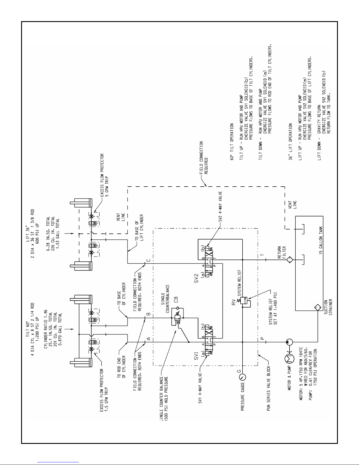
9.2 Hydraulic Plumbing Schematic
Southworth Products PUN Manual26
Page 27
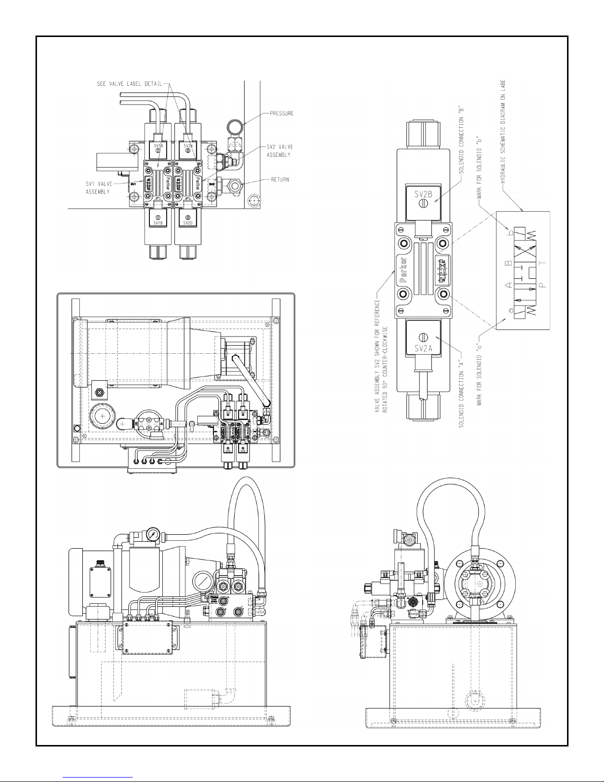
9.3 Hydraulic Arrangement
Southworth ProductsPUN Manual PUN Manual27
Page 28
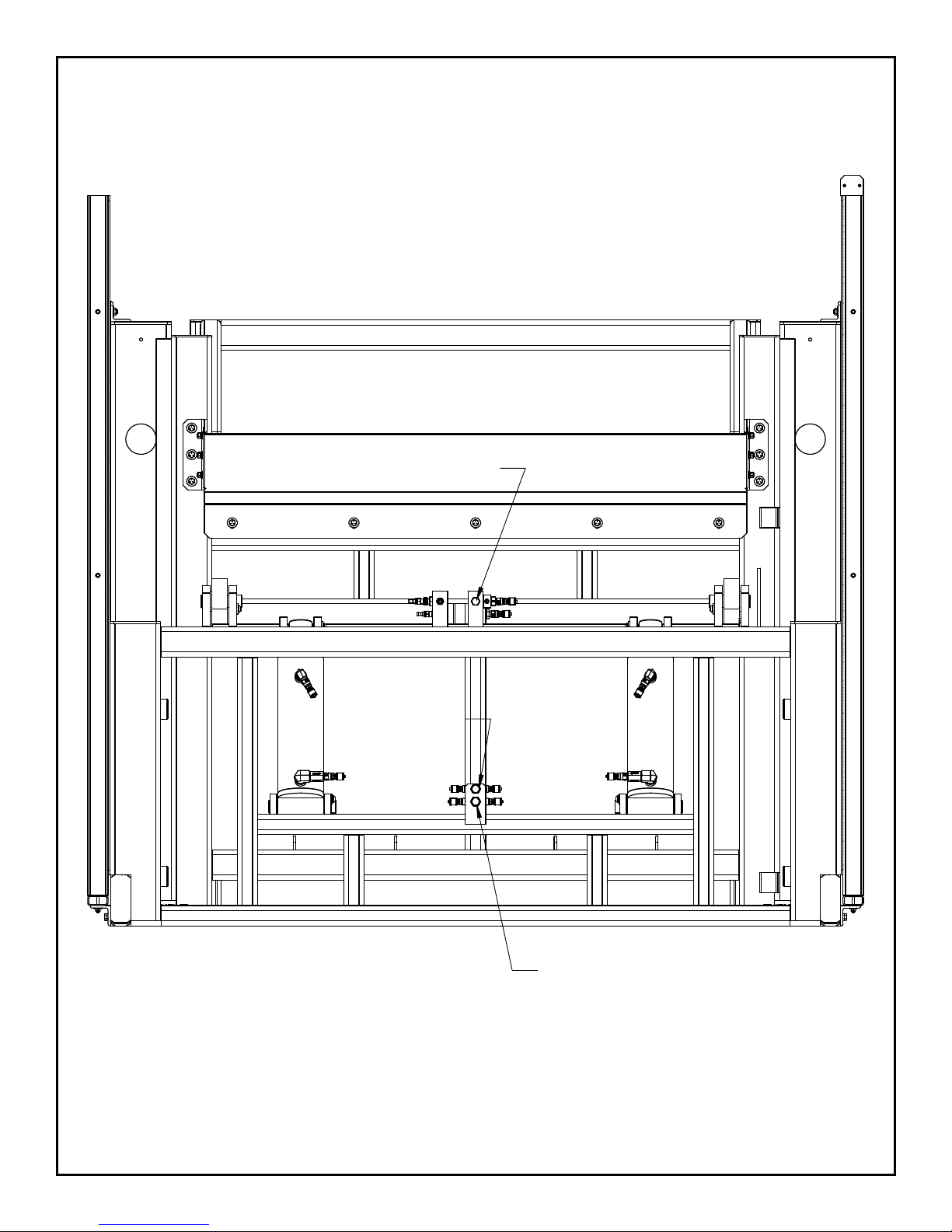
9.4 Hydraulic Connections
CONNECT PORT C TO
RIGHT CONNECTION
CONNECT
PORT A TO TOP
CONNECTION
CONNECT
PORT B TO
BOTTOM
CONNECTION
Southworth Products PUN Manual28
Page 29
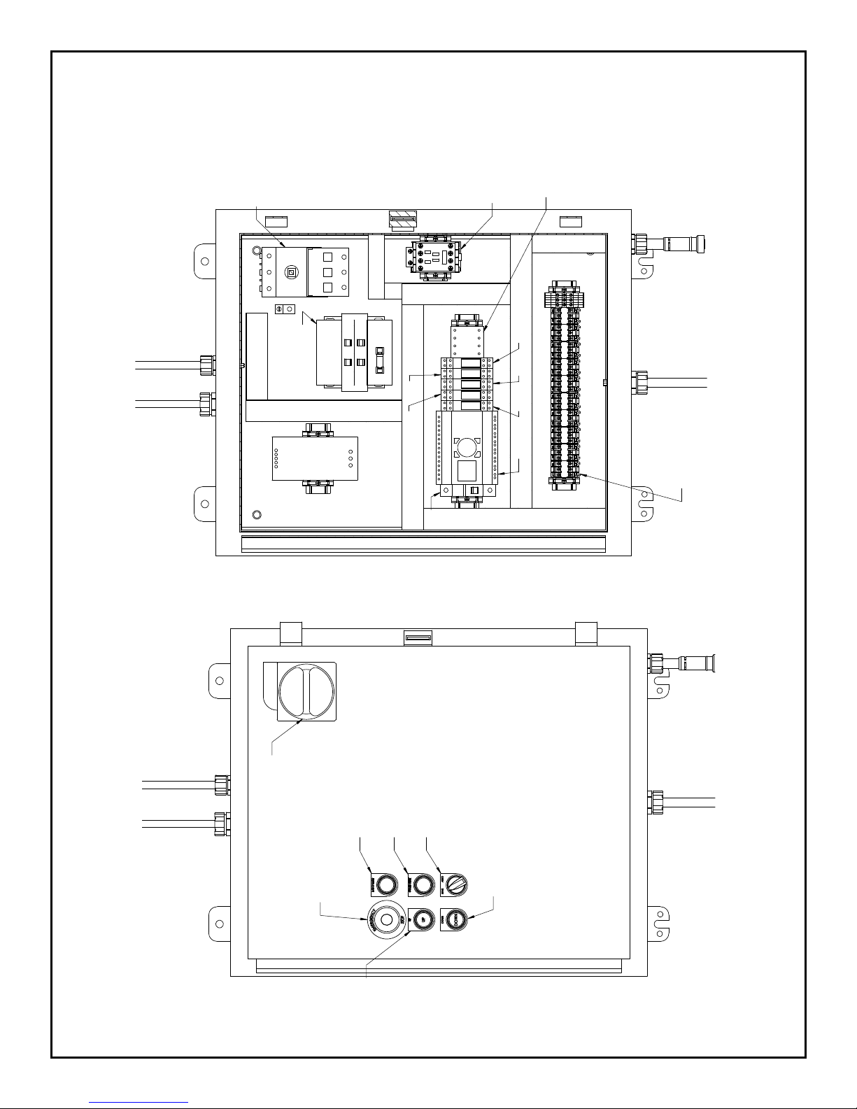
10. Electrical Information
MAIN DISCONNECT SWITCH
BUTTON
10.1 Control Panel
MAIN
DISCONNECT
SWITCH
TRANSFORMER
24 VDC
3FU
1FU
POWER
SUPPLY
2FU
4FU
5FU
6FU
4CR
2CR
MOTOR
CONTACTOR
3CR 5CR
1CR
PLC
MASTER
CONTROL
RELAY
TERMINAL BLOCK
E-STOP RESET
EMERGENCY
STOP (E-STOP)
BUTTON
GUARD RESET
7FU
MAN/AUTO MODE SELECTOR
DOWN BUTTON
Southworth ProductsPUN Manual PUN Manual29
UP
Page 30
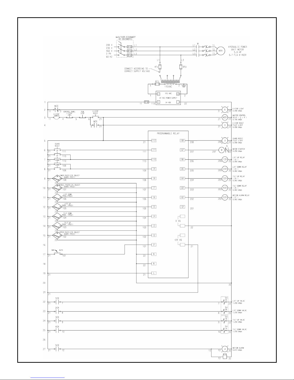
10.2 Electrical Schematic
Southworth Products PUN Manual30
Page 31

11. Warranty & Contact Information
Southworth Products Corp. warrants this product to be free from defects in material or
workmanship for a period of one (1) year from date of shipment, providing claim is made in
writing within said year. This warranty shall not cover failure or defective operation caused
by misuse, misapplication, negligence or accident, exceeding recommended capacities,
or altering or repairing, unless alteration is authorized by Southworth Products Corp.
Except as set forth herein, there are no other warranties, express or implied, including the
warranties of merchantability and tness for a particular purpose, all of which are hereby
excluded.
Southworth Products Corp. makes no warranty or representation with respect to the
compliance of any product with state or local safety or product standard codes, and
any failure to comply with such codes shall not be considered a defect of material or
workmanship under this warranty. Southworth Products Corp. shall not be liable for any
direct or consequential damages arising out of such noncompliance.
Southworth Products Corp’s obligation under this warranty is limited to the replacement or
repair of defective components at its factory or another location at Southworth Products
Corp.’s discretion. The Southworth Warranty is for product sold with in North America. For
products shipped outside North America the warranty will be for replacement of defective
parts only. Labor is not included. This is buyer’s sole remedy. Except as stated herein,
Southworth Products Corp. will not be liable for any loss, injury, or damage to persons or
property, nor for direct, indirect, or consequential damage of any kind resulting from failure
or defective operation of said material or equipment.
This warranty may be altered only in writing by Southworth Products Corp., Portland,
Maine.
Southworth Products Corp. is widely acknowledged as the leading maker of hydraulic lifts
and materials-handling equipment. Southworth machines are rugged and reliable, and
are designed to provide years of trouble-free service. The designs are based on extensive
engineering experience. These are good reasons for specifying Southworth machines in
your plant.
SOUTHWORTH PRODUCTS CORP.
P.O. Box 1380, Portland, ME 04104-1380
Telephone: 800-743-1000 • 207-878-0700
Fax: 207-797-4734
www.SouthworthProducts.com
Southworth ProductsPUN Manual PUN Manual31
 Loading...