

Page 1
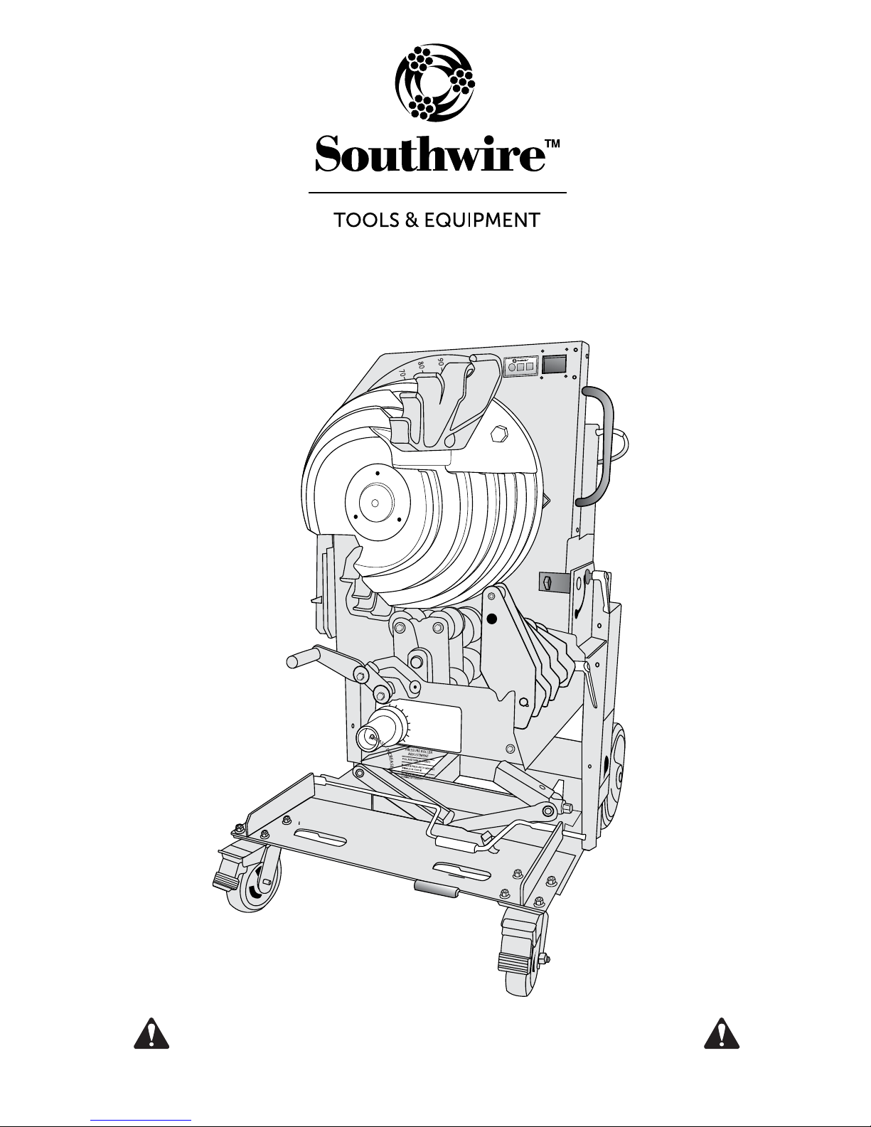
BENDMAX
Operating Instructions
™
Power Bender (PB-2000)
Read and understand all of the instructions and safety information
in this manual before operating or servicing this tool.
FAILURE TO OBSERVE THESE WARNINGS CAN RESULT IN SEVERE INJURY OR DEATH.
Page 2

BEFORE OPERATING THIS TOOL,
READ AND UNDERSTAND ALL OF THE
INSTRUCTIONS AND SAFETY
INFORMATION IN THIS MANUAL
TAB LE O F CO NT EN TS
Description.....................................................................Page 2
Safety..............................................................................Page 2
Purpose of this Manual...................................................Page 2
Important Safety Information..........................................Pages 3-4
Grounding Instructions…………………………………....Page 5
.Pages 5-6
Features..........................................................................Page 7
Transportation................................................................ Page 7
Setup..............................................................................Pages 8-9
Operation........................................................................Pages 10-15
.Page 16
Troubleshooting..............................................................Page 16
Warranty.........................................................................Pages 17
1
Page 3

DESCRIPTION
The Southwire BENDMAX™ Power Bender is intended to bend
3/4" to 2" conduit and pipe.
This bender has the capability to accommodate the following
types of conduit and pipe:
• Electrical Metallic Tubing
• Intermediate Metallic Conduit
• Rigid Conduit
SAFETY
Safety is essential in the use and maintenance of Southwire Tools
and Equipment. This instruction manual and any markings on the
tool provide information for avoiding hazards and unsafe practices
related to the use of this tool. Observe all of the safety information
provided.
WARNING:
Read and understand all instructions and safety
information in this manual before operating or servicing this tool.
PURPOSE OF THIS MANUAL
This manual is intended to familiarize all personnel with the safe
operation of the Southwire BEND
MAX
™
Power Bender. Keep this
manual available to all personnel. Replacement manuals are available at no charge at www.southwiretools.com.
All specifications are nominal and may change as design
improvements occur. Southwire Tools and Equipment shall
not be liable for damages resulting from misapplication or
misuse of its products.
2
Page 4
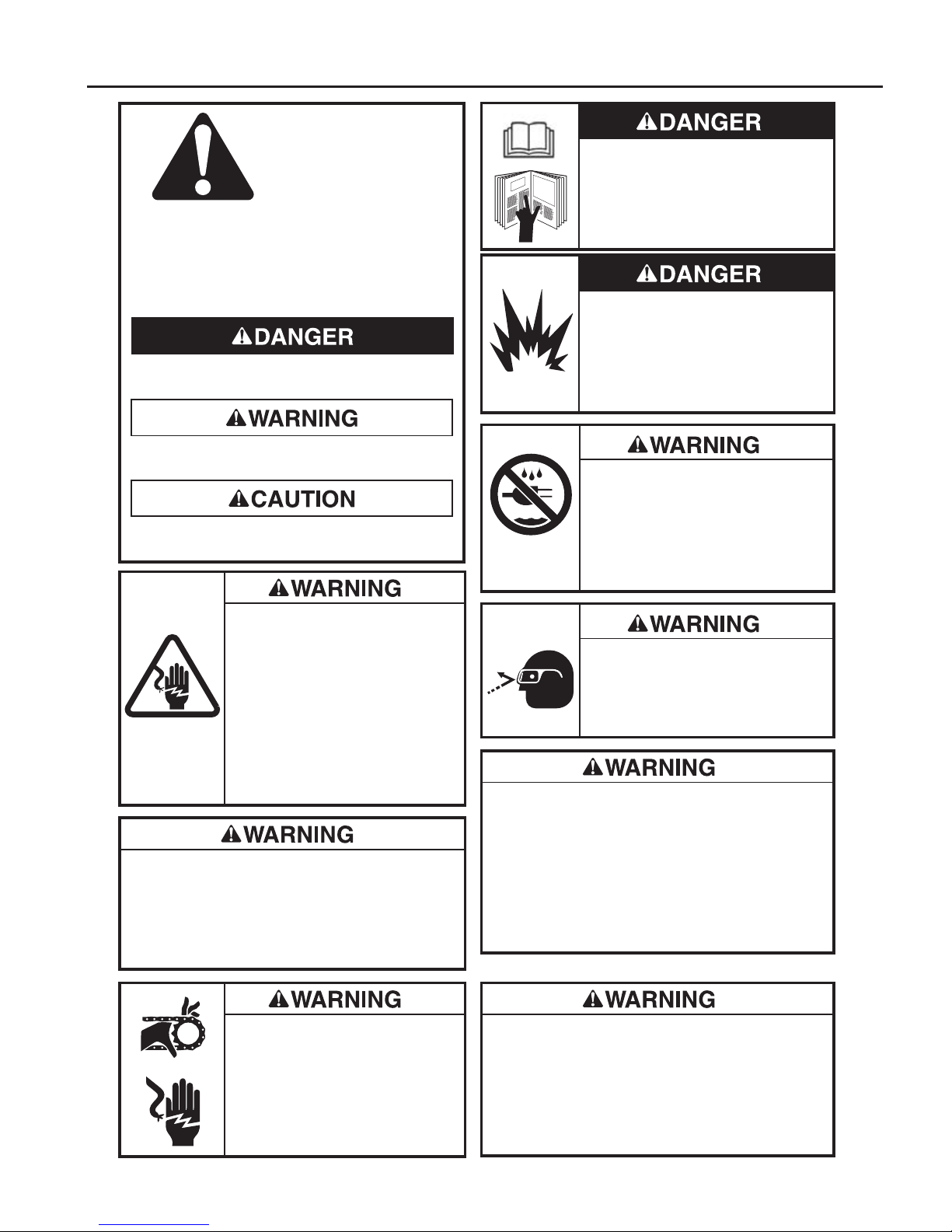
IMPORTANT SAFETY INFORMATION
SAFETY
ALERT
SYMBOL
This symbol is used to call your attention to hazards
or unsafe practices which could result in an injury or
property damage. The signal word, defined below,
indicates the severity of the hazard. The message
after the signal word provides information for preventing or avoiding the hazard.
Immediate hazards which, if not avoided, WILL
result in severe injury or death.
Hazards which, if not avoided, COULD result in
severe injury or death.
Hazards or unsafe practices which, if not avoided,
MAY result in injury or property damage.
Read and understand all of the
instructions and safety information in
this manual before operating or
servicing this tool.
Failure to observe this warning could
result in severe injury or death.
Do not use this tool in a hazardous
environment. Hazards include flammable
liquids, gases, or other materials. Using
this tool in a hazardous environment can
result in a fire or explosion.
Failure to observe this warning could
result in severe injury or death.
• Do not use in dangerous environment.
Do not use power tools in damp or wet
locations, or expose them to rain. Keep
work area well lighted.
• Do not immerse the pendant switch in water
or any other liquid.
Failure to observe these warnings could
result in severe injury or death.
Electrical Shock Hazard:
• Inspect the power cord before use.
Repair or replace the cord if damaged.
• Connect the power cord to a 120 volt,
20 amp receptacle on a ground fault
protected circuit only. Refer to
“Grounding Instructions.”
• Do not modify the power cord or plug.
• Disconnect the unit from power
before servicing.
Failure to observe this warning could
result in severe injury or death.
For continued protection against risk of fire and electric
shock, replace ONLY with same manufacturer, type,
and rating of fuse. Refer to the “Maintenance” section
of this manual.
Failure to observe this warning could result in severe
injury or death.
• Keep guards in place and in working
order.
• Remove any tools from bender before
operating. Form habit of checking to
see that all tools are removed from
bender before turning it on.
Failure to observe these warnings
could result in severe injury or death.
Always use safety glasses. Everyday
glasses only have impact resistant lenses;
they are NOT safety glasses. When using in
dusty enviornment, use face or dust mask.
Failure to wear eye protection could result
in serious eye injury from flying debris.
• Reduce the risk of unintentional starting. Make sure
switch is in off position before plugging in.
• Never leave tool running unattended. Turn power off.
Do not leave tool until it comes to a complete stop.
• Disconnect tools before servicing and when changing
accessories such as shoes, rollers, and the like.
Accidental start-up could result in serious injury.
Failure to observe these warnings could result in severe
injury or death.
• Never stand on tool.
Serious injury could occur if the tool is tipped.
• Do not overreach. Keep proper footing and balance
at all times.
Failure to observe these warnings could result in severe
injury or death.
3
Page 5
IMPORTANT SAFETY INFORMATION cont.
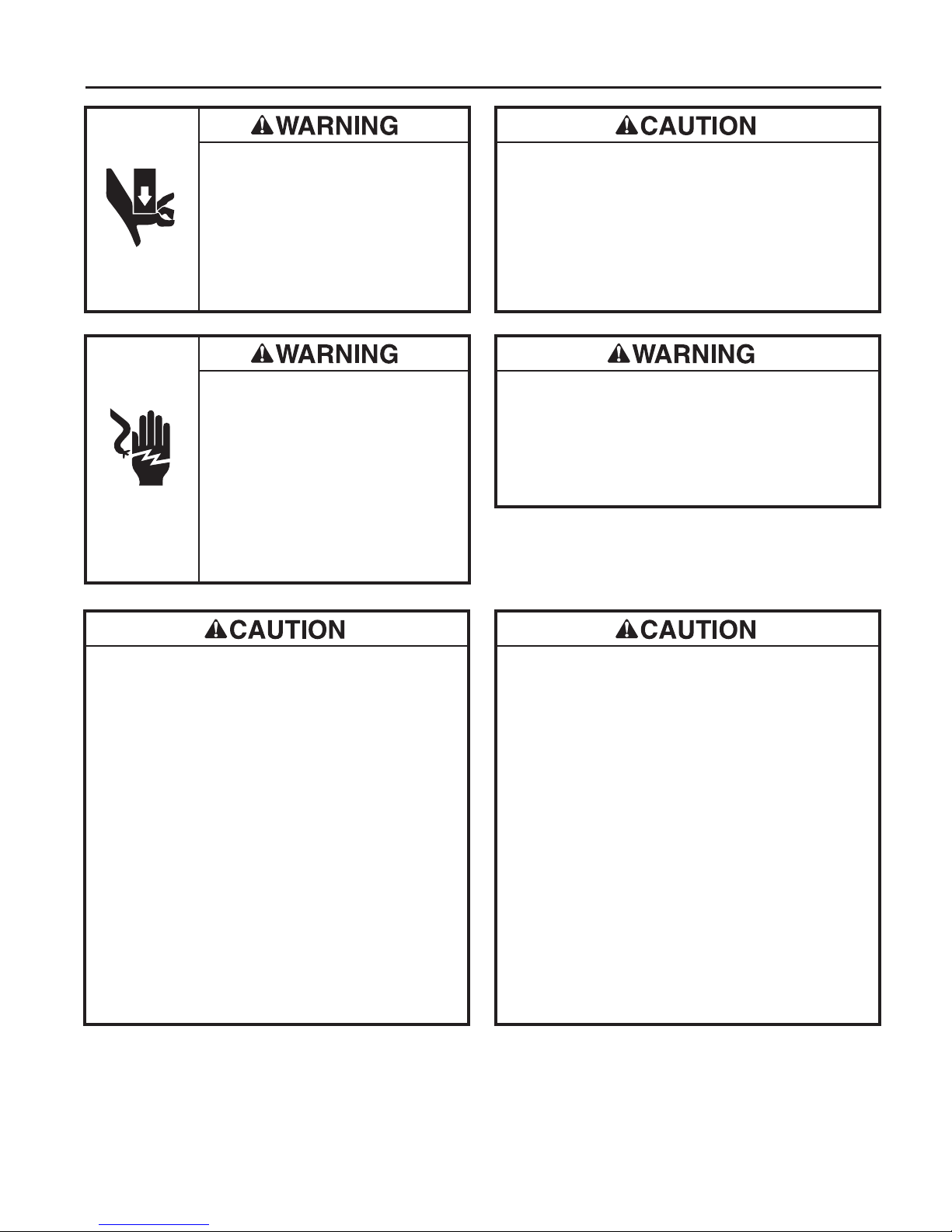
Pinch points:
• Keep hands away from bending shoe,
rollers, and conduit when bender is in
use.
• Support conduit when unloading.
Conduit can become loose and fall if
not properly supported.
Failure to observe these warnings could
result in severe injury or death.
Extension cords:
• Use only three-wire, 12 AWG
extension cords that have three-prong
grounding-type plugs and three-hole
receptacles that accept tool’s plug.
• Do not use extension cords that are
longer than 30 m (100 ft).
• Repair or replace damaged
extension cords.
Failure to observe these warnings
could result in severe injury or death.
• Select the appropriate shoe groove and support roller
for the type and size of conduit before bending.
• Do not bend conduit over 96 degrees. Overbending
could result in the other shoe hook colliding with the
conduit.
Failure to observe these precautions may result in
severe injury or property damage.
Adjust fork spacing to match fork tubes on bender.
Ensure front wheel brakes are engaged before inserting
forks into fork tubes.
Failure to observe these warning could result in
severe injury or death.
• Inspect the bender before use. Replace worn,
damaged, or missing parts with Southwire replacement
parts. A damaged or improperly assembled component
could break and strike nearby personnel.
• Maintain tools with care. Keep tool clean for best and
safest performance. Follow instructions for lubricating
and changing accessories.
• Check damaged parts. Before further use of the tool,
a guard or other part that is damaged should be
carefully checked to determine that it will operate
properly and perform its intended function.
Check for alignment of moving parts, binding of moving
parts, breakage of parts, mounting, and any other
conditions that may affect its operation.
A guard or other part that is damaged should be
properly repaired or replaced.
Failure to observe these precautions may result in
severe injury or property damage.
• Conduit moves rapidly as it is bent.
The patch conduit must be clear of obstructions.
Be sure clearance is adequate before starting the bend.
• Wear proper apparel. Do not wear loose clothing,
gloves, neckties, rings, bracelets, or other jewelry
which may get caught in moving parts, Nonslip
footwear is recommended. Wear protective hair
covering to contain long hair.
• Do not force rollers or alter tool. It will do the job
better and safer at the rate for which it was designed.
• Use right tool. Do not force tool or attachment to do
a job for which it was not designed.
• Use this tool for the manufacturer’s intended purpose
only. Use other than that which is instructed in this
manual can result in injury or property damage.
Failure to observe these precautions may result in
severe injury or property damage.
FAILURE TO OBSERVE THESE WARNINGS CAN RESULT
IN SEVERE INJURY OR DEATH
4
Page 6
GROUNDING INSTRUCTIONS
Electrical Shock Hazard:
• Do not modify the plug provided with the tool.
• Connect this tool to a grounded receptacle on a 20 amp ground fault protected circuit.
Failure to observe these warnings could result in severe injury or death.
This tool must be grounded. In the event of a malfunction or breakdown,
an electrical ground provides a path of least resistance for the electric current.
This path of least resistance is intended to reduce the risk of electric shock.
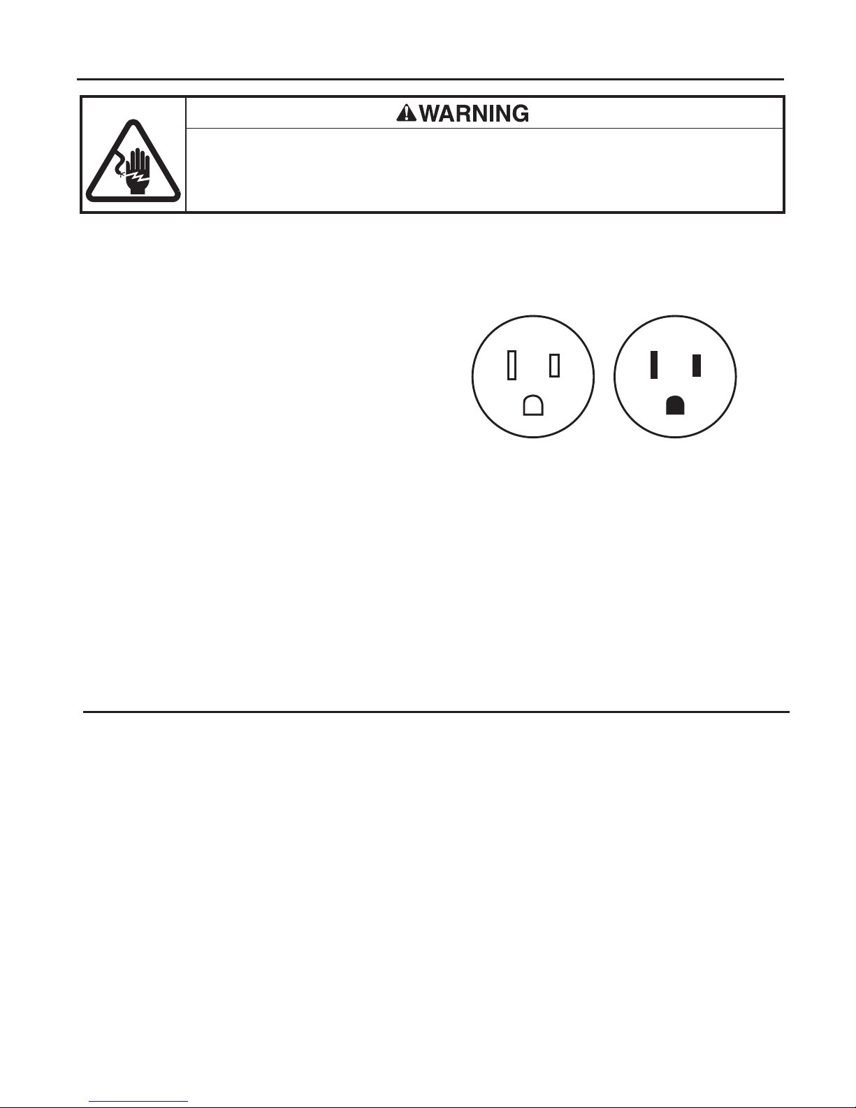
This tool’s electric cord has a grounding conductor and a grounding plug as
shown. Do not modify the plug.
Connect the plug to a corresponding
receptacle that is properly installed and
grounded in accordance with all national
and local codes and ordinances.
Do not use an adapter.
Do not modify the plug provided. If it will not fit the outlet, have the proper
outlet installed by a qualified electrician. Improper connection of the
equipment-grounding conductor can result in a risk of electric shock.
The conductor with insulation having an outer surface that is green with or
without yellow stripes is the equipment-grounding conductor. If repair or
replacement of the electric cord or plug is necessary, do not connect the
equipment-grounding conductor to a live terminal.
Check with a qualified electrician or service personnel if the grounding
instructions are not completely understood, or if in doubt as to whether
the tool is properly grounded.
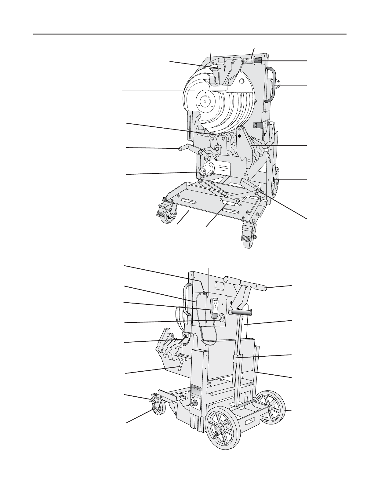
IDENTIFICATION (See Front and Back Views on Page 6)
1. 3/4”- 2” EMT, IMC, Rigid Bending Shoe
2. Bending Hooks (EMT- Gray)
(IMC, Rigid-Black)
3. Analog Protractor
4. Zero and Spring back Setup
5. Digital Display
6. Bender Support Handle
7. 3/4”- 2” Rollers
8. Elevation Travel Indicator
9. Elevation Control Screw Jack
10. Elevation Control Screw Handle
11. Fork Tube
12. Squeeze Adjustment Knob
13. Roller Assembly Lock handle
1
14. 1
/2”- 2” EMT and IMC Roller
15. Locking Tilt Handle
16. Power Receptacle
17. Hand Pendent
18. Pendent Control Cable
19. 15 Amp Fuse
20. Power Switch
21. Push Cart Handle
22. Motor
23. Conduit Support Stand
24. Gearbox
25. Wheel
26. Caster
27. Caster Brake
28. 2 Degree Fine Adjustment Handle
5
Page 7
IDENTIFICATION cont.
FRONT
VIEW
1
14
13
12
3
2
11
10
4
5
6
7
8
9
BACK
VIEW
19
18
17
16
15
28
27
26
20
21
22
23
24
25
6
Page 8

FEATURES
• Single shoe bending of 3/4" to 2" EMT, IMC, and Rigid conduit.
• Four large wheels for easy transportability.
• Adjustable elevation control allows for ergonomic working height.
• Squeeze adjustment allows for variations in conduit.
• Back lite digital display for easy viewing.
• Fork tubes provided for easy forklift mobility.
• Onboard conduit support stand for easy feeding of conduit into bender.
• Front locking casters to securely keep bender in place during use.
• Quick release lock handle to easily pivot bender between vertical
and horizontal positions.
• Billet aluminum hand pendent for durability.
• 2 Degree fine adjustment for easy leveling.
• Programmable spring back setting for accurate bending.
TRANSPORTING OF BENDER
Refer to the “Identification” section of this manual.
To transport the BEND
MAX
on the ground
™
1. Ensure bender is in the vertical position. If bender is in the horizontal position,
loosen locking tilt handle (15) by turning counter clockwise and lift up on bender
support handle (6). Once in the vertical position align base of locking tilt handle
into slot and turning the handle clockwise till tight.
2. Ensure the bender is in the lowest setting.
Refer to section labeled “ELEVATION OF THE BEND
MAX
”
™
to insure bender is in the lowest position for transport.
3. If not already installed, place conduit support stand (23) on the back of the
bender in supplied hooks.
4. Unlock caster brakes (27) and use push cart handle (21) to maneuver bender
to desired location.
5. Lock caster brakes (27) by pushing down with foot once transport is complete.
To transport this bender by fork lift
1. Ensure caster brakes (27) are locked by pressing down with foot.
2. Ensure the bender is in the lowest setting.
Refer to section labeled “ELEVATION OF THE BEND
MAX
™
”
to insure bender is in the lowest position for transport.
3. Insert the forks into the fork tubes (11) at bottom of bender.
Adjust fork spacing to match fork tubes on bender.
Ensure front wheel brakes are engaged before inserting forks into fork tubes
Failure to observe this warning could result in severe injury or death.
7
Page 9
SETUP
Always use safety glasses. Everyday glasses only have impact resistant lenses;
they are NOT safety glasses.
When using in dusty enviornment, use face or dust mask.
Failure to wear eye protection could result in serious eye injury from flying debris.
Refer to the “Identification” section of this manual.
1. Position the bender so that there is room to load conduit and
engage the front caster brakes (27).
2. Place the bender in the desired vertical or horizontal bending position.
Refer to section labeled “CHANGING THE BENDING PLANE OF
THE BEND
3. Plug approved 12 AWG extension cord into the power receptacle (16)
from grounded 20 amp outlet.
Extension cords:
• Use only three-wire, 12 AWG extension cords that have three-prong grounding-type plugs and three-hole
receptacles that accept tool’s plug.
• Do not use extension cords that are longer than 30 m (100 ft).
• Repair or replace damaged extension cords.
Failure to observe these warnings could result in severe injury or death.
MAX
™
”.
4. Plug the Pendent Control Cable (18) into housing under
Power Switch (20) then into Hand Pendent (17).
LEVELING OF THE BENDMAX
™
Refer to the “Identification” section
of this manual.
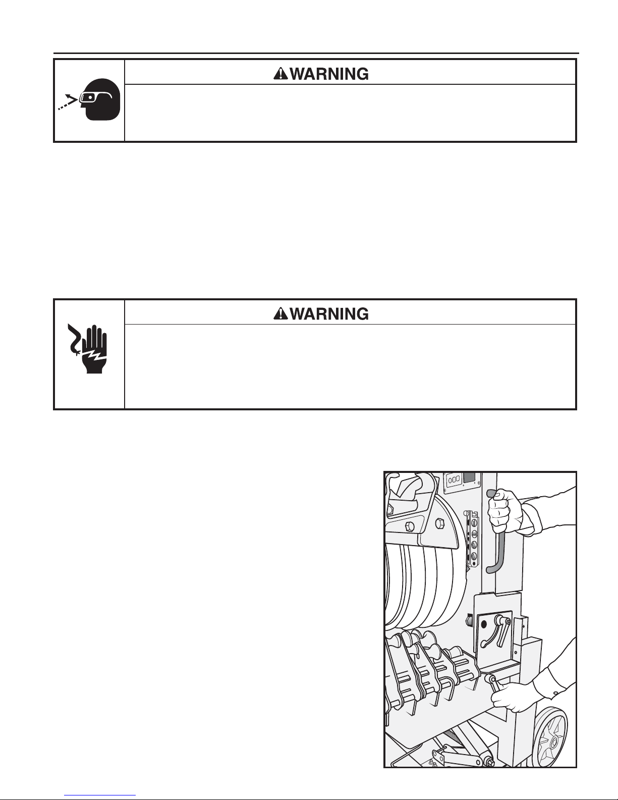
1. To level the
BENDMAX
™
Power Bender,
place a magnetic level to the front plate
just under the digital display (5). Loosen
the two degree fine adjustment handle (28)
and use Bender Support Handle (6) to find
the level position on the magnetic level.
Tighten fine adjustment handle (28) to
secure in place as shown in (Fig 1).
Fig. 1
8
Page 10
SETUP cont.
100
90
CHANGING THE BENDING PLANE OF THE BENDMAX
™
Refer to the “Identification” section of this manual.
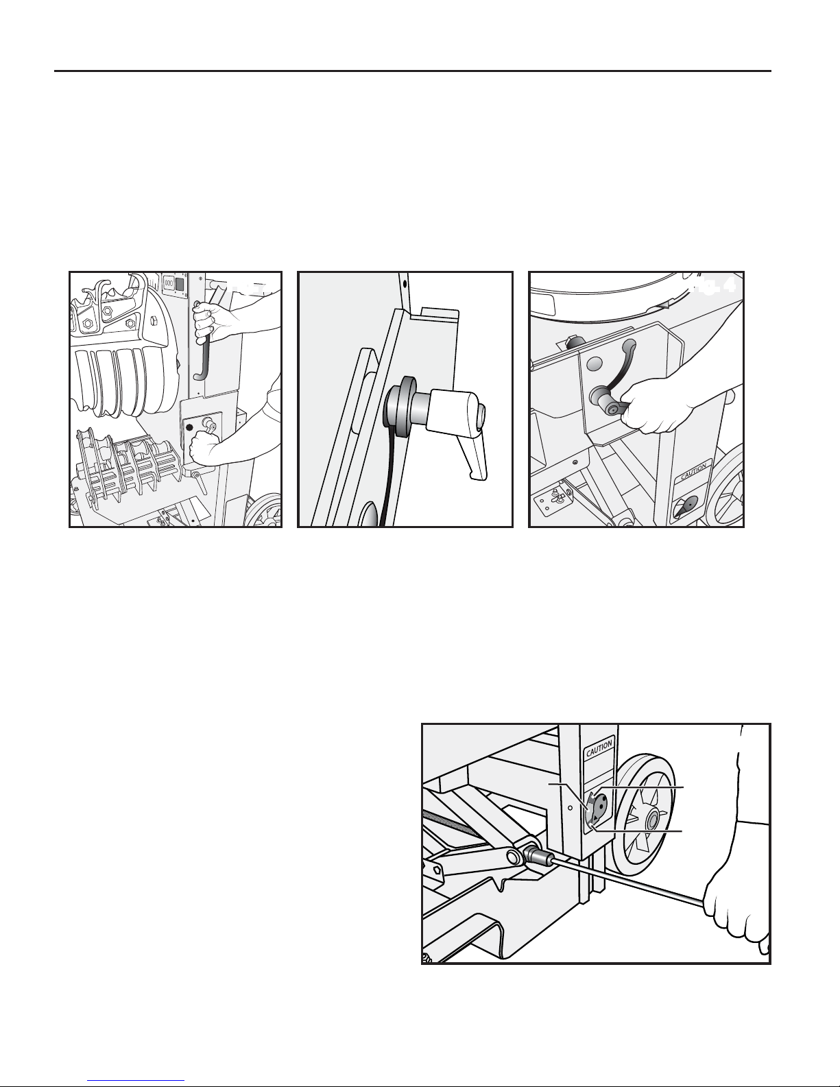
1. Rotate the Locking Tilt Handle (15) counter clockwise to loosen and free up
the bending platform (Fig 2). Place hand on Bender Support Handle (6) and
allow the bender head platform to transition backwards. Once in the
horizontal plane, align the anchor set spacer (Fig 3) into slot and tighten
Locking Tilt Handle (15) by turning clockwise to secure in place as seen in (Fig 4).
Fig. 2 Fig. 3 Fig. 4
ELEVATION OF THE BENDMAX
™
Refer to the “Identification” section of this manual.
1. To raise the elevation control for the
BEND
MAX
™
Power Bender, remove
the elevation control screw handle (10) from its stored location. Insert socket
end of handle onto the end of the elevation control screw jack (9) and rotate
handle clockwise to raise the unit upwards or counter clockwise to lower
unit as shown in (Fig 5).
CAUTION: Ensure you carefully
observe the Elevation Travel Indicator (8) to ensure you stay within the
GREEN area when using an 18V
Drill to raise and lower bender.
Ensure you stay out of the RED
area on the travel indicator as
shown in Fig. 5 by the arrow.
ure to stay in the green range
could result in elevation control
jack damage.
Fail-
Green
Fig. 5
Fig. 5
Red
Red
2. Once proper height has been found secure elevation control
screw handle (10) back in its stored location.
9
Page 11
OPERATION
Do not use this tool in a hazardous
environment. Hazards include flammable
liquids, gases, or other materials. Using
this tool in a hazardous environment can
result in a fire or explosion.
Failure to observe this warning could
result in severe injury or death.
Electrical Shock Hazard:
• Inspect the power cord before use. Repair or replace the cord if damaged.
• Connect the power cord to a 120 volt, 20 amp receptacle on a ground fault protected circuit only.
Refer to “Grounding Instructions.”
• Do not modify the power cord or plug.
• Disconnect the unit from power before servicing.
Failure to observe this warning could result in severe injury or death.
Pinch points:
• Keep hands away from bending shoe,
rollers, and conduit when bender is in use.
• Support conduit when unloading.
Conduit can become loose and fall if
not properly supported.
Failure to observe these warnings could
result in severe injury or death.
CALIBRATING THE DIGITAL PROTRACTOR
Refer to the “Identification” section of this manual.
ZERO AND SPRING BACK SET UP
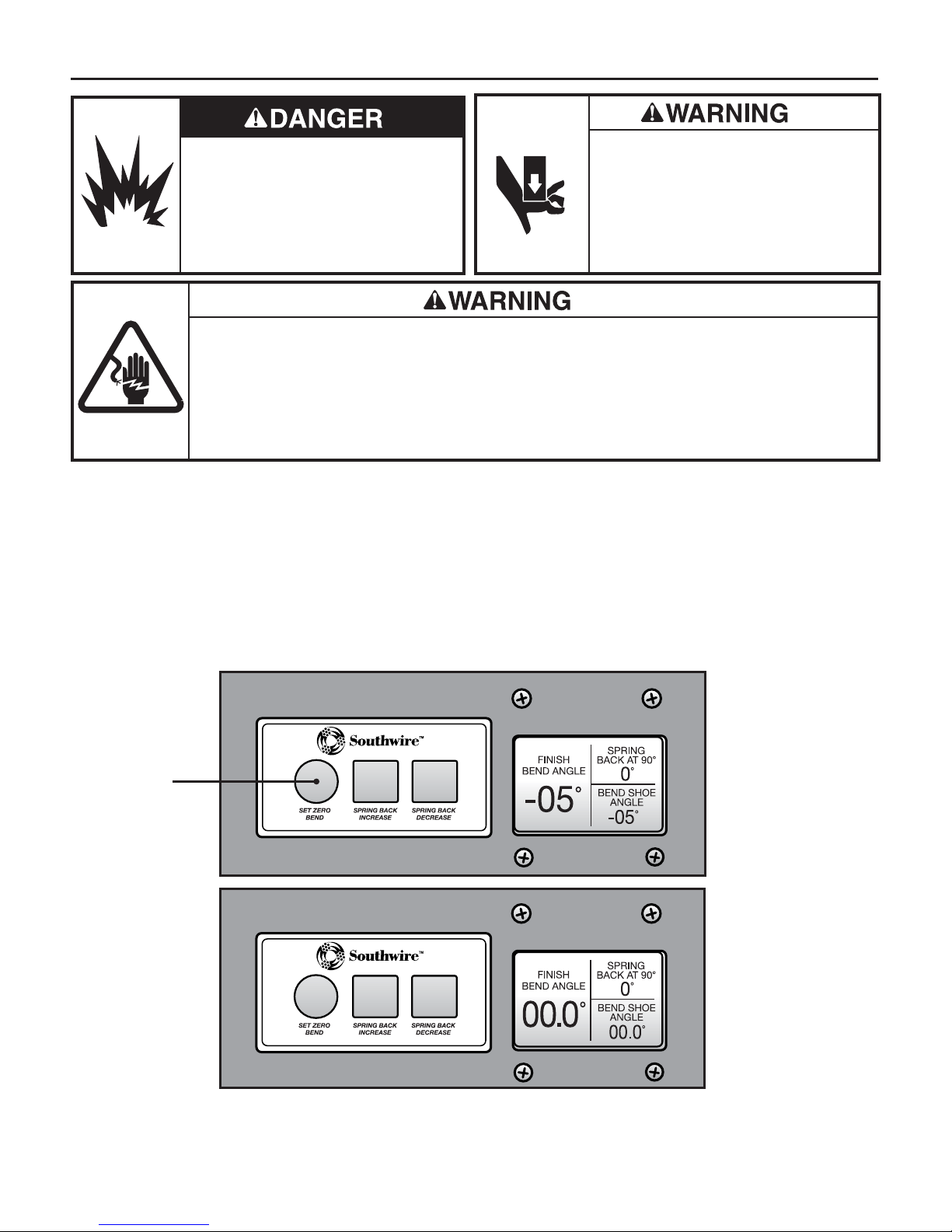
1. To Zero the Digital Protractor place yellow “Arrow” on bending shoe
to zero on the analog protractor and press the “SET ZERO BEND”
soft key on set up panel (4) as shown in (Figs. 6 and 7).
Fig. 6
Press
Fig. 7
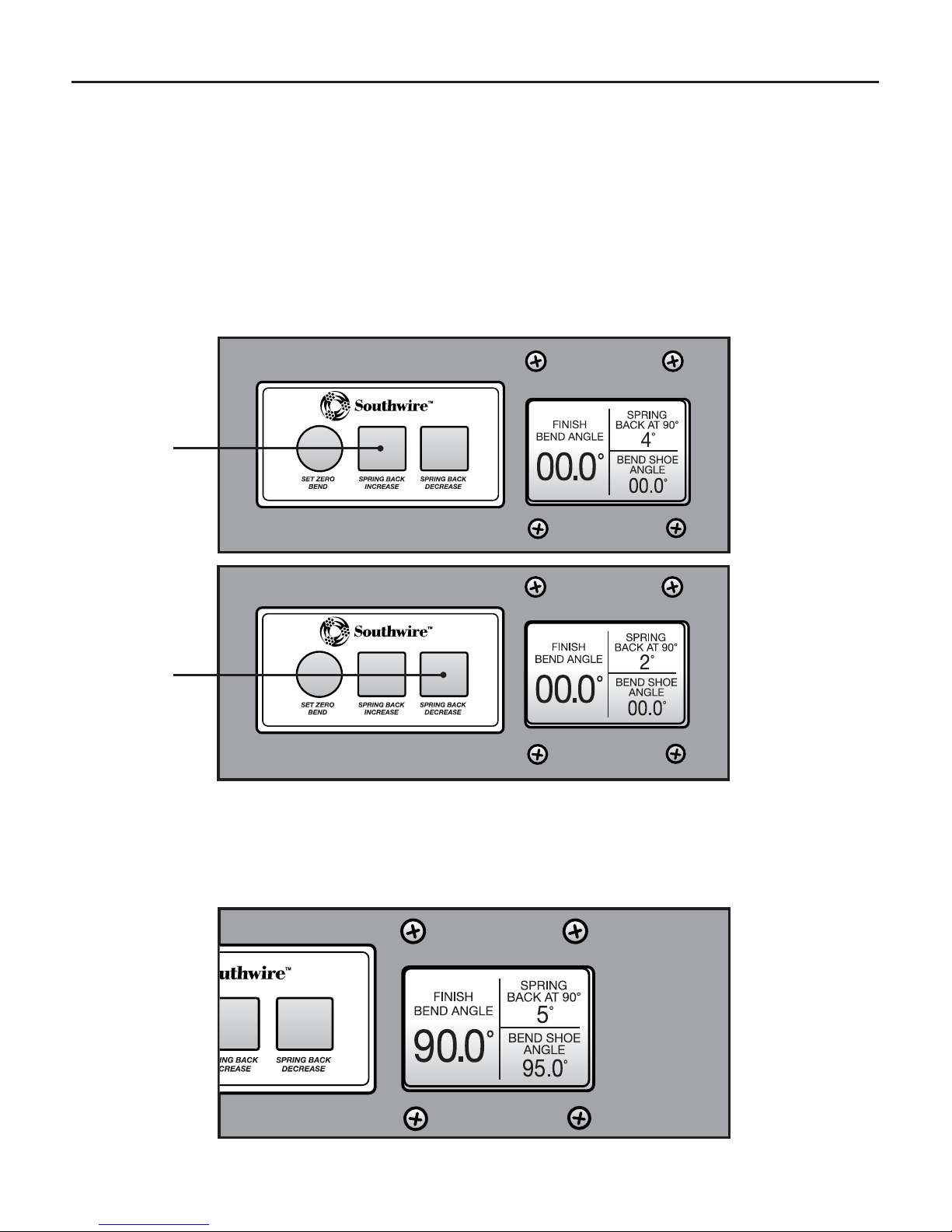
2. To set spring back, start at 4 degrees of spring back.
Minor adjustments can be made after a test bend has been made.
10
Page 12
OPERATION cont.
CALIBRATING THE DIGITAL PROTRACTOR cont.
Refer to the “Identification” section of this manual.
ZERO AND SPRING BACK SET UP cont.
3. Locate Zero and Spring Back Set-up panel (4) and press the
“SPRING BACK INCREASE OR SPRING BACK DECREASE”
soft key until desired spring back is shown on top right corner
of digital display (5) as shown in (Figs. 8 and 9).
Fig. 8
Press
Fig. 9
Press
4. This setting will compensate for the spring back and adjust the
bending degrees of the digital display shown on the left side of
the display as shown in (Fig 10).
Fig. 10
11
Page 13
OPERATION cont.
SQUEEZE ADJUSTMENT
Refer to the “Identification” section of this manual.
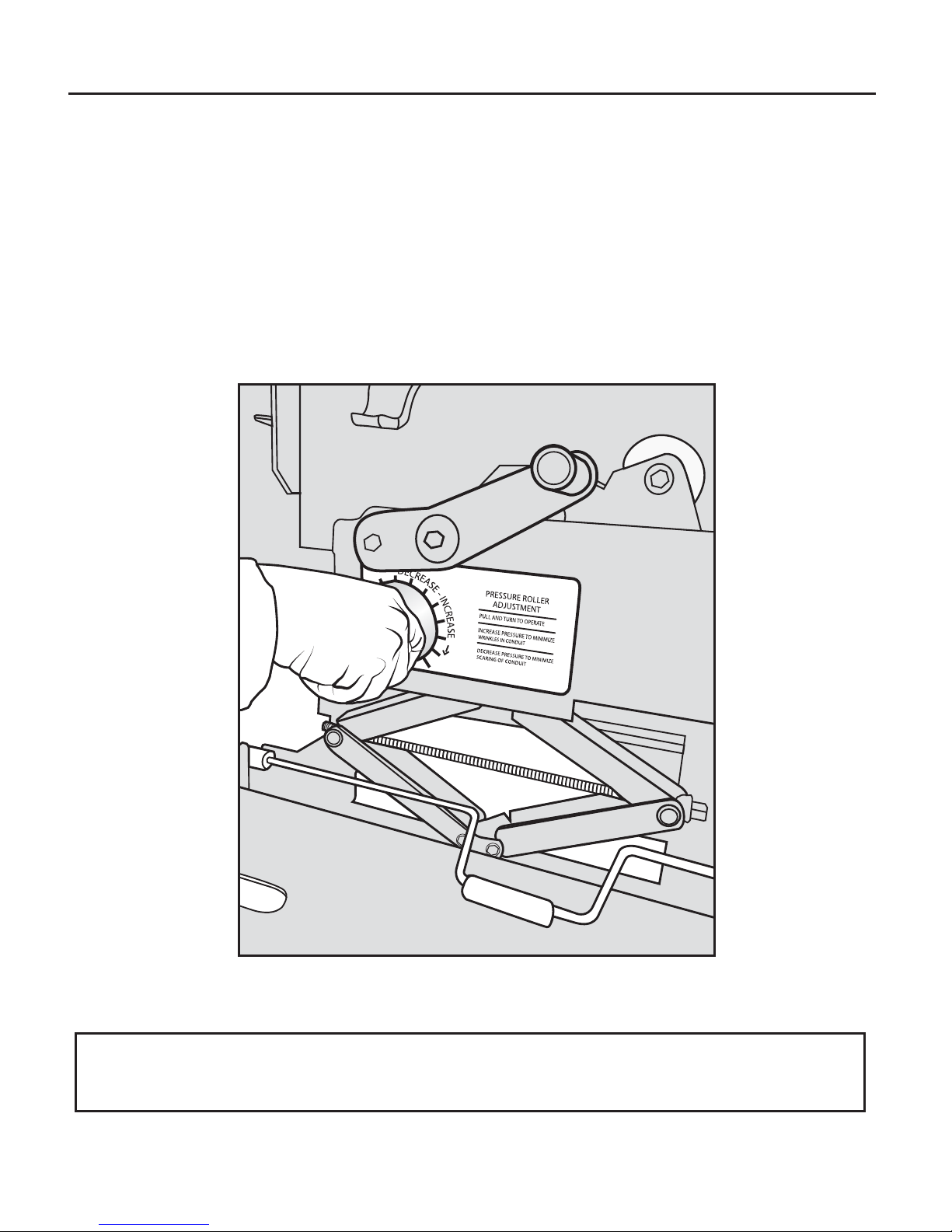
1. When bending 1
1
/2", or 2" EMT or IMC, the amount of squeeze
applied to the conduit can be adjusted to compensate for conduit
variations. The squeeze is adjustable by turning the squeeze
adjustment knob (12) to increase or decrease the amount of tension
needed to properly seat the conduit as shown in (Fig 11).
Fig. 11
Note: Test bend should be performed to ensure proper squeeze is set.
Minor adjustments may be required.
12
Page 14
OPERATION cont.
BENDING
Refer to the “Identification” section of this manual.
1. Turn on bender by pressing on the green power switch (20).
2. Use the BEND, RETURN or JOG button on hand pendent (17)
to orient the shoe so that the hooks of the conduit type to be bent
are around the 7 o’clock (approximately – 5°) position on the analog
or digital display.
(Gray hooks are for EMT; Black hooks are for IMC and Rigid.)
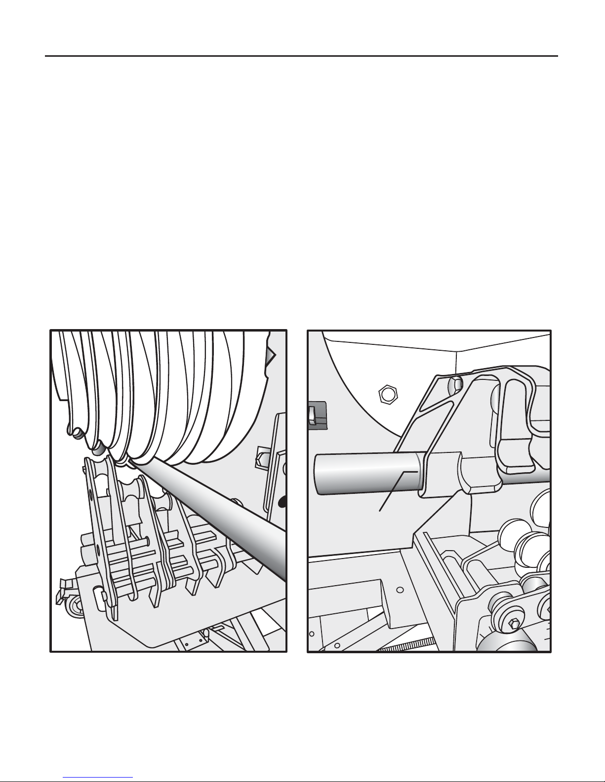
3. Load the conduit into the appropriate sized roller and groove (Fig 12)
so that the bending mark is aligned with the front edge of the hook
as shown in (Fig 13).
Fig. 12 Fig. 13
Mark
13
Page 15
OPERATION cont.
BENDING cont.
4. Bending the conduit
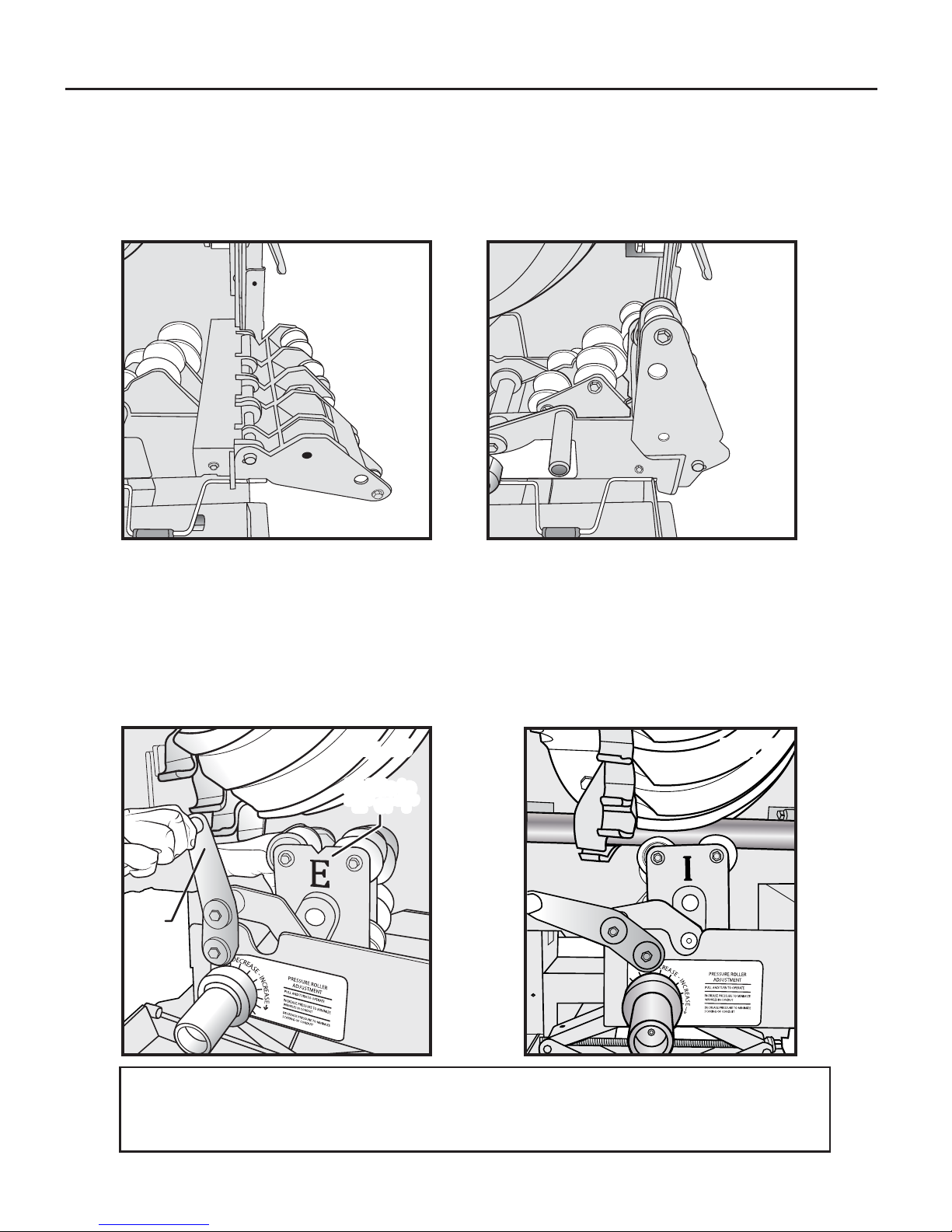
4A. For 3/4” through 1 1/4” EMT, IMC, or rigid conduit, ensure the 3/4” - 2” Rollers (7)
1
are in the upright position, as shown in (Figs. 14, 15). For 1
”
/2
- 2” rigid conduit
sizes utilize the 3/4”- 2” rollers (7) while in the upright position.
Fig. 14
Fig. 15
4B. For 1 1/2” and 2” EMT or IMC conduit, use the 1 1/2”- 2” EMT and IMC
Roller (14) by turning the assembly to reflect “E” for EMT or “I” for IMC.
EMT and IMC Roller Lock Handle (13) may have to be pulled to the left to
allow roller assembly to be rotated (Fig 16). Once properly selected, raise
the rollers from the retracted position to the upright (engaged) position by
rotating the EMT and IMC Roller Lock Handle (13) counter clockwise to lock
and secure conduit in place, as shown in (Fig 17).
Fig. 17Fig. 16
Rotate to
Rotate to
“E ” or “ I”
“E ” or “ I”
Pull
handle
to left
Note: Test bend should be performed to ensure proper squeeze is set.
Minor adjustments may be required. To make adjustments to the squeeze setting, refer to section labeled “SQUEEZE ADJUSTMENT”.
14
Page 16
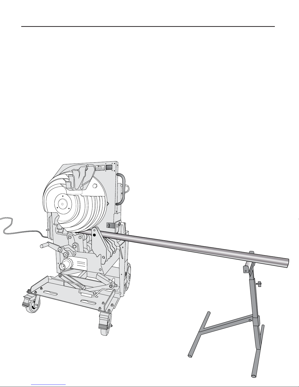
OPERATION cont.
CONDUIT SUPPORT STAND
Refer to the “Identification” section of this manual.
™
1. Each BEND
MAX
(23) located on the back of the bender.
2. To use this stand, Remove it from its stored position by lifting stand
off the frame mounted hooks and place to the right as viewed from
the front of bender. The stands height can be adjusted by loosening
the screw knob and lifting up on the roller. Once proper height is
obtained, screw knob clockwise to tighten.
3. Once conduit is loaded into the bender rollers, minor adjustments can
be made to Conduit Support Stand to facilitate easy feeding of conduit
into the bender.
4. This feature can help to eliminate the need to find a coworker to hold
and help load long runs of conduit as seen in (Fig 18).
Power Bender comes with a Conduit Support Stand
Fig. 18
90
80
70
15
Page 17

ADDITIONAL ITEMS
A. Personal protective equipment
B. Portable band saw or other conduit cutting device
C. Appropriate reamer or filing tool
D. Tape measure
E. Black marker
F. Magnetic level (Southwire MCB Level)
G. EMT, IMC or Rigid Conduit
SPECIFICATIONS
• Model #PB2000
• Stock # 59840601
™
• Name - BEND
• Length - 38”
• Width - 30”
• Height - 50”
MAX
Power Bender
• Weight - 600 lbs (273kg)
• Patent Pending
TROUBLESHOOTING
PROBLEM CAUSE DIAGNOSIS CURE
1
2 No power at bender
3
4
Bender will not
operate
Power to bender but
will not operate
Motor runs but
will not bend
Bad extension power cord
Power switch in the off
Chain from transfer shaft
Chain from jack shaft to shoe
Power source
position
Fuse blown Inspect 15 amp fuse Replace fuse
Motor bad Check for power at motor Replace motor
broken
Bad gear box
sprocket broken
Check for voltage at power
source
Ohm extension cord for
broken wire
Check power switch is lite
green when in the "ON"
position
Remove cover and visually
check for broken parts
Motor running but no output
through gear box
Remove cover and visually
check for broken parts
If power is on, go to (#3)
Replace extension cord
Replace switch
Replace broken parts
Replace gear box
Replace broken parts
Key between motor and
gearbox missing
Bender operates in
5
only one direction
Bad Bend/Return switch
Bad pendent cord Ohm for broken wire Replace pendent cord
Remove motor from gearbox Replace key
Ohm switch for open contact
or shorted contacts
Replace Pendent
16
Page 18

WARRANTY ON SOUTHWIRE CONTRACTOR EQUIPMENT
What Does This Warranty Cover?
Five-Year Limited Warranty on Contractor Equipment
Under Southwire’s Contractor Equipment 5-Year Limited Warranty, Southwire Company, LLC warrants that all
Southwire Contractor Equipment will be free from manufacturer defects for a period of five (5) years from the date
of the original end user’s purchase. The following products are excluded from this 5-Year Limited Warranty and are
subject to separate warranty terms: rope, blades, dies, draw studs, grips, Southwire Contractor Equipment electronic
components, and Material Boxes. Under this 5-Year Limited Warranty, the following are also excluded and
Southwire Company, LLC will have no liability for any of the following: normal wear and tear resulting from product
use and damage arising out of misuse, abuse, modification, and improper product maintenance.
This warranty also does not cover Southwire Contractor Equipment products that have been modified by any party
other than Southwire Company, LLC or its authorized third party designee. This 5-Year Limited Warranty is not
transferrable to or enforceable by any person other than the product’s original end user.
One-Year Limited Warranty on Rope, Blades, Dies, Draw Studs, Grips, and Southwire
Contractor Equipment Electronic Components
Under this 1-Year Limited Warranty, Southwire Company, LLC warrants that all Southwire Ropes, Blades, Dies, Draw
Studs, Grips, and Southwire Contractor Equipment Electronic Components will be free from manufacturer defects for
a period of one-year from the date of the original end user’s purchase. Under this 1-Year Limited Warranty for the
aforementioned Southwire Contractor Equipment items, the following are excluded and Southwire Company, LLC
will have no liability for any of the following: normal wear and tear resulting from product use and damage arising
out of misuse, abuse, modification, and improper product maintenance. This warranty also does not cover
Southwire Contractor Equipment that has been modified by any party other than Southwire Company, LLC
or its authorized third party designee. This 1-Year Limited Warranty is not transferrable to or enforceable by any
person other than the product’s original end user.
Exclusion of Incidental, Consequential, Indirect, Special and Punitive Damages
SOUTHWIRE MAKES NO WARRANTY THAT SOUTHWIRE CONTRACTOR EQUIPMENT PRODUCTS WILL BE
MERCHANTABLE OR FIT FOR ANY PARTICULAR PURPOSE. SOUTHWIRE MAKES NO OTHER WARRANTY,
EXPRESSED OR IMPLIED, OTHER THAN THE RELEVANT WARRANTY SPECIFICALLY SET FORTH IN THIS
WARRANTY SECTION. SOUTHWIRE WILL NOT BE LIABLE FOR ANY INCIDENTAL, CONSEQUENTIAL,
INDIRECT, SPECIAL, OR PUNITIVE DAMAGES FOR ANY BREACH OF THIS LIMITED LIFETIME WARRANTY.
Some states do not allow the exclusion or limitation of incidental or consequential
damages, so the above limitation or exclusion may not apply to you.
Warranty Claim Information/ How Do You Get Service?
For all warranty, customer service, and product return authorizations and inquiries,
please contact Southwire’s Tools & Assembled Products at:
Southwire Tools & Assembled Products
840 Old Bremen Road
Carrollton, GA, 30117
Phone Number: 1.855.SW.Tools
1. All warranty claims must be approved by Southwire’s Tools & Assembled Products Warranty Department prior
to return of product. If Southwire determines that a product is defective, Southwire will, at its option, repair or
replace defective products or defective product components, free of charge.
2. Upon approval, Southwire will issue a Product Return Authorization Form which will include instructions on how
and where to return the product. The product serial number and the original date of delivery must be set forth
on the Product Return Authorization Form.
3. Southwire will cover standard freight charges (FedEx Ground rate) incurred in connection with products that
Southwire ultimately determines to be defective.
4. All defective components and defective products that Southwire replaces under these Warranties will become
Southwire’s property and will be retained by Southwire.
Fixing Your Product When it is Out of Warranty
Southwire is happy to provide information about where a purchaser can send a product for repair at consumers’
own expense, please contact 1.855.SW.tools or visit www.southwiretools.com/tools/home.do for more
information about servicing for Southwire Products.
17
Page 19

southwiretools.com
1-855-SW-T00LS
Toll Free Technical Help
Contents Made in USA
Product distributed by Southwire Company, LLC
One Southwire Drive, Carrollton, GA 30119
©2016 Southwire Company, LLC. All rights reserved.
05/ 16
PB-2000 Manual
 Loading...