

Page 1
OWNER’S MANUAL EU EDITION
Installation
Operation
Maintenance
Skystream Energy Europe GmbH
A wholly-owned subsidiary of Southwest Windpower, Inc.
Mannesmannstr. 6
50996 Cologne
Germany
Tel: +49 (0) 221 16 53 94 50
[email protected]
www.skystreamenergy.eu
© November 2010 Skystre am E ne rgy Eu rope
All Rights Reserved
Page 2

Page 3
Skystream Energy Europe
Congratulations on your purchase and welcome to our family!
Dear Skystream 3.7® Owner,
Thank you for your purchase of Skystream. You have just selected the most technologically advanced, cost-effective renewable energy appliance available
for a home or small business. We congratulate you on your choice and are confident you will experience years of dependable service.
Before going any further, please complete and return the enclosed Warranty Registration Card. The conditions of your warranty are dependent upon
the proper installation of Skystream. Furthermore, this will assure you of being kept up-to-date with the latest developments from Skystream Energy
Europe. These include new options, performance tips, updated software to maximize output and user notices. It is important to know that we do not sell or
distribute your information to any third party. We understand your privacy is important.
If you have any questions or comments, we would like to hear from you. Please call during working hours (Monday-Friday 09:00 - 15:00 CET). Our phone
number is +49 (0) 221 16 53 94 50.
Again, welcome to our family and thank you for investing in the future of wind energy with Skystream.
Sincerely,
Skystream Energy Europe
Enter the serial and model number below
Serial Number __________________________________
Model Number __________________________________
Skystream Owner’s Manual, EU Edition
3-CMLT-1357-01
Revision: B
Page 4

IMPORTANT SAFETY INSTRUCTIONS
READ THESE IN STRUCTIONS IN THEIR ENTIRETY BEFORE INSTALLING OR OPERATING.
PROFESS IONAL I NSTALLATION: Skystream
Energy Europe strongly recommends Skystream
be installed by trained professionals.
1) SAVE THESE INSTRUCTIONS. This manual contains important instructions
for Skystream that must be followed during installation and maintenance.
2) Read, understand and respect all warnings.
3) Do not install Skystream around standing water.
4) Do not install Skystream on a windy day.
5) Install Skystream in accordance with National Electric Code (NEC) and local
building codes.
6) Always obtain a building permit before construction.
7) A minimum of 2 adults are required to safely lift or move Skystream. Use proper
equipment such as hydraulic hoists to lift Skystream.
8) Always wear appropriate protective personal equipment such as closed toe
work shoes, hard hat, work gloves, and safety glasses when working on or
installing Skystream.
9) If unusual noise or abnormal operation is observed from Skystream, turn off the
machine and contact authorized service personnel.
10) Shut Skystream “OFF” if ice accumulates on blades to avoid possible injury
resulting from ice flying off blades.
11) This wind generator complies with international safety standards and therefore
the design or its installation must never be compromised.
a. Do not open the inverter cover, doing so without factory authorization
will void the warranty.
b. Apply the proper torque to all fasteners.
c. Torque field wire connections to Skystream to 2.3-2.5 N·m.
Refer to Electrical Connections section of this manual
(Section 2-1-2).
d. Install only on a Professional Engineer (PE) certified tower.
e. Do not paint the blades.
12) Use only proper grounding techniques as established by the NEC.
13) Properly complete the warranty registration card; failure to complete
and return the card may affect your warranty.
14) Skystream must be installed in accordance with this manual and local
and national building codes. Failure to comply with the manual and
local codes will affect and possibly void your warranty.
15) Skystream uses high voltage and is potentially dangerous. Be sure to
use all safety precautions at all times.
4 Skystream 3.7® Owner’s Manual, EU Edition, Rev B
Page 5

Radio (RF) Interference
Radio (RF) Interference (EU)
Skystream 3.7 has been tested and found to comply with the limits for a class B
digital device, pursuant to Part 15 of the FCC Rules (US Federal Communications
Commission). These limits are designed to provide reasonable protection against
harmful interference in a residential installation. Skystream generates, uses and
can radiate radio frequency energy and, if not installed and used in accordance with
the instructions, may cause harmful interference to radio communications. However,
there is no guarantee that interference will not occur in a particular installation.
If Skystream does cause harmful interference to radio or television reception,
which can be determined by turning the Skystream on and off, you are encouraged
to correct the interference by one or more of the following measures:
• Reorient or relocate the Skyview Interface Module or Remote Display.
• Increase the separation between Skystream and Skyview Interface Module or
Remote Display.
In this manual
IMPORTANT:
Please take note
Complies to European Standards EN 61000-6-3 (2007), EN 61000-6-2 (2005),
EN 61000-3-2 (1995), EN 61000-3-3 (2000).
TIP: Helpful information
to ease the installation
Professional installation
highly recommended
Warning: Risk of injury or
death - proceed with extreme
caution
Skystream 3.7® Owner’s Manual, EU Edition, Rev B 5
Page 6

TABLE OF CONTENTS
IMPORTANT SAFETY INSTRUCTIONS _____________________ 4
RADIO INTERFERENCE _________________________________ 5
SKYSTREAM 3.7® WARRANTY ____________________________ 7
SKYSTREAM 3.7® SPECIFICATIONS _______________________ 8-9
EUROPEAN GRID STANDARDS __________________________ 10
PRIOR TO INSTALLATION ______________________________ 11
INTENDED USE ________________________________________ 11
UNINTENDED USE _____________________________________ 11
INSTALLATION PERSONNEL _____________________________ 12
SITING – FINDING THE BEST LOCATION FOR SKYSTREAM __ 14
LOCAL REQUIREMENTS ________________________________ 14
INSTALLATION ________________________________________ 15
INTRODUCTION ________________________________________ 15
WIRE SIZING ___________________________________________ 15
GROUNDING __________________________________________ 16
UTILITY PANEL CONNECTIONS __________________________ 16
ELECTRICAL CONNECTIONS TO SKYSTREAM _____________ 17-18
LIGHTNING PROTECTION _______________________________ 18
INSTALLING SKYSTREAM ON A TOWER ___________________ 19
BOLTING SKYSTREAM TO THE TOWER ____________________ 20-21
BLADES, NOSECONE AND ANTENNA ASSEMBLY __________ 22-24
APPENDICES
Appendix A: Electrical Diagrams
1 Typical Grid Connection ___________________________ 3
2 Typical Battery Charging___________________________ 4
Appendix B: Tower Grounding
1 Introduction_______________________________________ 4
2 Grounding Techniques______________________________ 4-9
Appendix C: Lightning Protection
1 Introduction_______________________________________ 4
2 Lightning Protection Data ___________________________ 4-9
Appendix D: Compliance/Certification Documents
1 UL (US & Canada)_________________________________ 2-3
2 CE (Europe) ______________________________________ 4
OPERATION AND ADJUSTMENTS ______________________ 25
MANUAL OPERATION OF SKYSTREAM ____________________ 25
ADJUSTMENTS _________________________________________ 25
MAINTENANCE _________________________________________ 25-26
SERVICE ______________________________________________ 26
TROUBLESHOOTING ___________________________________ 26
EMERGENCY SHUTDOWN ______________________________ 26
KEY OPERATING CHARACTERISTICS _____________________ 27
DISPOSAL OF SKYSTREAM ______________________________ 28
FREQUENTLY ASKED QUESTIONS _______________________ 29
6 Skystream 3.7® Owner’s Manual, EU Edition, Rev B
Page 7

Skystream 3.7® Limited 5-Year Warranty
WIND TURBINE WARRANTY AGREEMENT
Hardware Warranty
Skystream Energy Europe GmbH, (“Skystream Energy”) will repair or replace free of
charge any part or parts of the Skystream Energy Skystream 3.7® wind generator determined by Skystream Energy to be defective in materials and/or workmanship under normal
authorized use consistent with product instructions for a period of five years from the date
the original purchaser (“Customer”) receives the wind generator (“Start Date”). This warranty extends only to the original purchaser. The Customer’s sole and exclusive remedy and
the entire liability of Skystream Energy, its suppliers and affiliates under the warranty is, at
Skystream Energy’s option, either (i) to replace the wind generator with new or reconditioned
wind generator, (ii) to correct the reported problem, or (iii) to refund the purchase price of the
wind generator. Repaired or replaced products are warranted for the remainder of the original
warranty period.
Restrictions
Problems with the wind generator products can be due to improper use, maintenance,
non-Skystream Energy additions or modifications or other problems not due to
defects in Skystream Energy’s workmanship or materials. No warranty will apply if the wind
generator (i) has been altered or modified except by Skystream Energy, (ii) has not been
installed, operated, repaired, or maintained in accordance with instructions supplied by
Skystream Energy (iii), or (iv) has been exposed to winds exceeding 140 mph (63 m/s), or
has been subjected to abnormal physical, thermal or electrical stress, misuse, negligence,
or accident. If Skystream Energy’s repair facility determines that the problem with the wind
generator is not due to a defect in Skystream Energy’s workmanship or materials, then the
party requesting warranty service will be responsible for the costs of all necessary repairs and
expenses incurred by Skystream Energy.
Warranty Claims & Return Procedures
In order to be eligible for service under this warranty the Customer MUST return the warranty registration card included with this Warranty Agreement within 60 days of purchasing
the wind generator. Additionally, the Customer must submit a service request for the wind
generator covered by this warranty within the warranty period by contacting Skystream Energy
in writing or via telephone and obtaining a Return Authorization (“RA”) number. This RA must
be obtained before returning any product under this warranty. Notification must include a
description of the alleged defect, the manner in which the wind generator was used, the serial
number, and the original purchase date in addition to the name, address, and telephone number of the party requesting warranty service. Within 3 business days of the date of notification,
Skystream Energy will provide the Customer with a RA number and the location to which the
Customer must return the defective wind generator. Any wind generator requiring warranty
repair shall be transported at the expense and risk of the party requiring warranty service,
including but not limited to proper packaging of the product. The Customer must return the
entire wind generator kit within 30 days after issuance of the RA number. Skystream Energy
will be under no obligation to accept any returned wind generator that does not have a valid
RA number. Customer’s failure to return the wind generator within 30 days of its receipt of
a RA number may result in cancellation of the RA. All parts that Skystream Energy replaces
shall become Skystream Energy’s property on the date Skystream Energy ships the repaired
wind generator or part back to the Customer. Skystream Energy will use all reasonable efforts
within five days of receipt of the defective wind generator to repair or replace such wind generator. If a warranty claim is invalid for any reason, the Customer will be charged at Skystream
Energy’s current rates for services performed and will be charged for all necessary repairs and
expenses incurred by Skystream Energy.
Disclaimer
EXCEPT FOR THE EXPRESSED WARRANTY SET FORTH ABOVE, SOUTHWEST
WINDPOWER DISCLAIMS ALL OTHER EXPRESSED AND IMPLIED WARRANTIES,
INCLUDING THE IMPLIED WARRANTIES OF FITNESS FOR A PARTICULAR PURPOSE,
MERCHANTABILITY AND NON-INFRINGEMENT. NO OTHER WARRANTY, EXPRESSED
OR IMPLIED, WHETHER OR NOT SIMILAR IN NATURE TO ANY OTHER WARRANTY
PROVIDED HEREIN, SHALL EXIST WITH RESPECT TO THE PRODUCT SOLD UNDER
THE PROVISIONS OF THESE TERMS AND CONDITIONS. SKYSTREAM ENERGY
EXPRESSLY DISCLAIMS ALL LIABILITY FOR BODILY INJURIES OR DEATH THAT MAY
OCCUR, DIRECTLY OR INDIRECTLY, BY USE OF THE PRODUCT BY ANY PERSON.
ALL OTHER WARRANTIES ARE EXPRESSLY WAIVED BY THE CUSTOMER.
Limitation of Liability
UNDER NO CIRCUMSTANCES WILL SKYSTREAM ENERGY OR ITS AFFILIATES OR
SUPPLIERS BE LIABLE OR RESPONSIBLE FOR ANY LOSS OF USE, INTERRUPTION
OF BUSINESS, LOST PROFITS,LOST DATA, OR INDIRECT, SPECIAL, INCIDENTAL,
OR CONSEQUENTIAL DAMAGES, OF ANY KIND REGARDLESS OF THE FORM OF
ACTION, WHETHER IN CONTRACT, TORT (INCLUDING NEGLIGENCE), STRICT LIABILITY OR OTHERWISE, RESULTING FROM THE DEFECT, REPAIR, REPLACEMENT,
SHIPMENT OR OTHERWISE, EVEN IF SKYSTREAM ENERGY OR ITS AFFILIATE OR
SUPPLIER HAS BEEN ADVISED OF THE POSSIBILITY OF SUCH DAMAGE. (Note: some
states and provinces do not allow the exclusion or limitation of incidental or consequential
damages, so these limitations may not apply to you). Neither Skystream Energy nor its affiliates or suppliers will be held liable or responsible for any damage or loss to any items or
products connected to, powered by or otherwise attached to the Hardware. The total cumulative liability to Customer, from all causes of action and all theories of liability, will be limited to
and will not exceed the purchase price of the product paid by Customer. This Warranty gives
the Customer specific legal rights and the Customer may also have other legal rights that vary
from state to state or province to province.
3-CMLT-1063
Skystream 3.7® Owner’s Manual, EU Edition, Rev B 7
Page 8
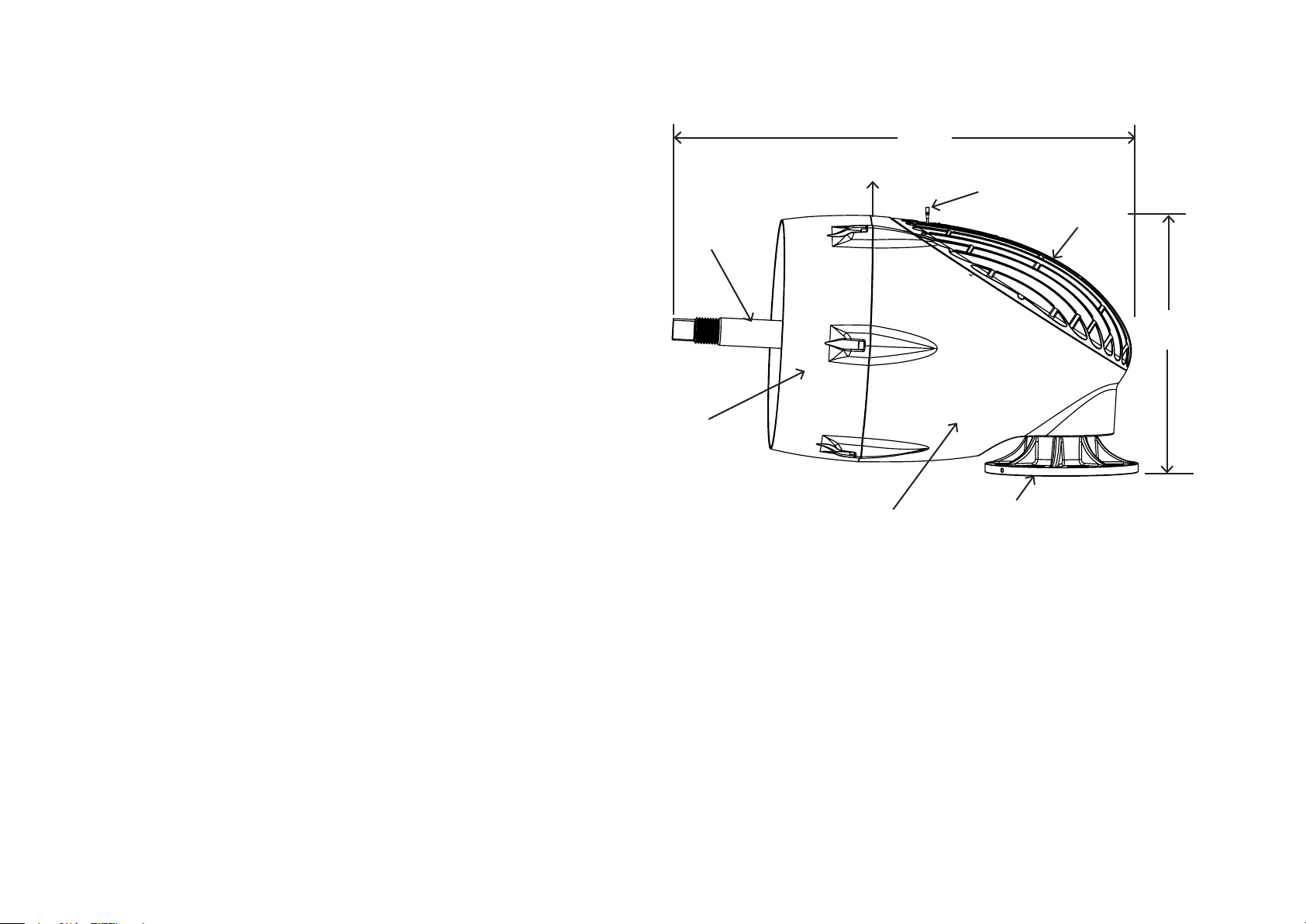
Skystream 3.7® Technical Specifications
64 cm
Model Skystream 3.7
Rated Capacity 2400 Watts
Weight 77 kg
Rotor Diameter 3.72 metres
Swept Area 10.87 m
Type Downwind rotor with stall regulation control
Direction of Rotation Clockwise looking upwind
Blades 3 Fiberglass reinforced composite
Rated Speed 50 - 330 rpm
Shutdown Speed 370 rpm
Tip Speed 9.7 - 63 m/s
Alternator Slotless permanent magnet brushless
Yaw Control Passive
Grid Feeding 230 Volt, 50 Hz, 1 Phase
Braking System Electronic stall regulation w/redundant relay switch control
2
Rotor Shaft
Face
CG
Nacelle
Antenna
Hatch Cover
48 cm
Yaw
Cut-in Wind Speed 3.5 m/s
Rated Wind Speed 13 m/s
User Monitoring Wireless 2 way interface remote system
Survival Wind Speed 63 m/s
Total Harmonic Distortion 2.7% at 2400W, meets UL1741 and IEEE1547.1requirements
IEC/EN 61000-3-2; Class A EU Limits; IEC 61400-21
8 Skystream 3.7® Owner’s Manual, EU Edition, Rev B
Frequency Accuracy +/- 0.05 Hz
Voltage Accuracy +/- 2.0 V (line to neutral)
Surge Rating IEEE 1547 Surge Rating B
European Requirement IEC 61000-4-5
Page 9
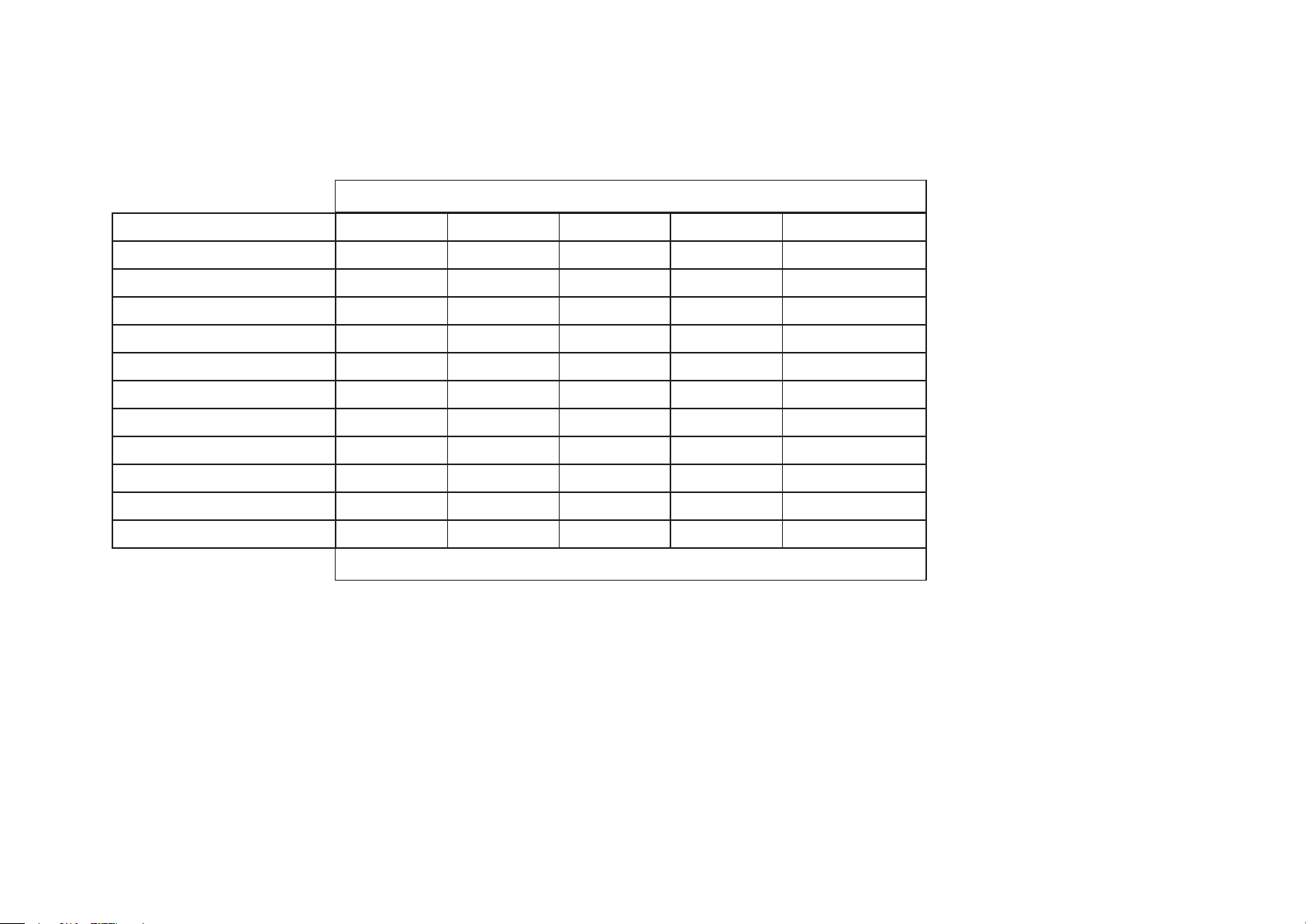
Skystream 3.7® Technical Specifications (continued)
Voltage and Frequency Trip Points
Condition -04 -06 -07 -09 Units
Voltage Stop, minimum 207.0 184.0 194.0 184.0 Volts
Voltage Stop, maximum 264.0 276.0 266.0 264.5 Volts
Voltage Fast Stop, minimum 115.0 115.0 195.5 184.0 Volts
Voltage Fast Stop, maximum 276.0 277.0 264.5 276.0 Volts
Voltage Start, minimum 208.0 185.0 196.5 185.0 Volts
Voltage Start, maximum 254.0 275.0 263.5 252.0 Volts
Frequency Stop, minimum 47.0 49.3 49.5 47.5 Hz
Frequency Stop, maximum 50.5 50.3 50.5 50.2 Hz
Frequency Start, minimum 47.1 49.4 49.6 47.4 Hz
Frequency Start, maximum 50.4 50.2 50.4 50.1 Hz
Minimum Start Time after fault 180.0 180.0 180.0 180.0 Seconds
Configuration -04 = UK , -06 = Italy , -07 = France , -09 = Germany
Tower Data (Loads calculated at 145 mph - 65 m/s)
Configuration
Note: Loads do not include safety factor. Skystream Energy Europe recommends minimum safety factor of 1.5
Shaft Thrust 2802 N
Downward 932 N
Bending Moment 1532 N·m
Skystream 3.7® Owner’s Manual, EU Edition, Rev B 9
Page 10

European Grid Standards
Skystream 3.7 complies with the relevant grid connetion requirements taken from
the following European Grid Codes:
• Verband der Electrizitätswirtschaft – VDEW –e.V. “Eigenerzeugungsanlagen am
Niederspannungsnetz” (generation units at low voltage level), 4th Edition,
2001, Germany
• ENA Energy Networks Association “Engineering Recommendation G83/1
– Recommendations for the connection of small-scale embedded generators
(up to 16 A per phase) in parallel with the public low voltage distribution net
works”’ September 2003
• EDF Référentiel Technique “Modele de Contrat de raccordment, d’accés et
d’exploitation pour une installation de production de puissant ≤ 36 kVA rac
cordée au Réseau Public de Distribution basse tension Conditions Générales”
/ Standard Form Agreement for the Connection, Access and Operation of
Power Generating Stations ≤ 36 kVA Connected to the Public Low Voltage Dis
tribution Network General Terms and Conditions”, Referentiel technique – NOP RES_55E, Vesion V6, 2006, France.
• DIN V VDE V 0126-1-1 (VDE V 0126-1-1) “Automatic disconnection device
between a generator and the public low voltage grid”, February 2006 Germany.
• Italian Standard CEI 11-20 “Electrical energy production systems and uninter
ruptible power systems connected to LV and MV networks”
• ÖVE/ÖNORM prEN 50438 “ Requirements for the connection of micro-co
generators in parallel with public low-voltage distribution system”, 01.10.2004
10 Skystream 3.7® Owner’s Manual, EU Edition, Rev B
Page 11
PRIOR TO INSTALLATION
Intended Use
Skystream 3.7 is a wind powered electricity generator containing an integral AC
power inverter. It is designed to supplement the electrical power provided by the
local electrical utility company in residential applications by connecting directly
to the main AC utility panel. Skystream 3.7 may also be utilized to provide power
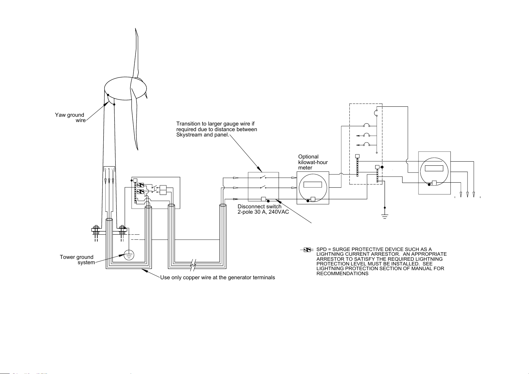
with battery based residential electrical systems or utility grid connected systems with battery backup. A typical Skystream installation is depicted in Fig. 1
of this manual.
Skystream 3.7 is designed to operate at sites with average wind speeds less
than 8.5 m/s - IEC (International Electro-technical Commission) Class II wind
conditions. The installation of Skystream at sites with higher average wind
speeds will accelerate component wear and require more frequent inspections.
Unintended Use
Utilizing Skystream 3.7 for other than its intended purposes or with inappropriate equipment or modifying Skystream is not authorized by Skystream Energy
Europe and will void the warranty and may result in serious or even fatal injury.
Observe the following precautions.
• Disconnect power to Skystream prior to servicing – observe “Lock-out” and
“Tag-out” procedures.
• Observe all Electrical Code Requirements including tower grounding require
ments, electrical disconnect switches, wires size and type. Reference the
appendices in this manual.
• Do not use unauthorized fasteners. Use fasteners supplied with Skystream.
Contact your dealer for authorized replacement fasteners.
• Observe fastener torque requirements.
• Do not attempt to modify Skystream in any fashion – internally or externally.
• Do not install blades other than those supplied with Skystream. Use only
genuine replacement blades supplied by Skystream Energy Europe,.
• Do not attempt to use a power source other than the wind to power
Skystream – for example connecting pulleys or as water powered turbine.
IMPORTANT: Precautions listed here cannot address all the possible misuses
of Skystream therefore contact Skystream Energy Europe. if there is any doubt
or question regarding the installation or use of Skystream.
• Skystream may only be installed on a tower approved by SWWP for use with
Skystream. Do not install Skystream on roofs or on unauthorized towers.
Skystream 3.7® Owner’s Manual, EU Edition, Rev B 11
Page 12
Your Skystream Shipment Includes:
Your Skystream shipment includes the following components. For your
convenience a small quantity of spare fasteners is included with each
Skystream. The quantities indicated below are quantities required to
assemble Skystream:
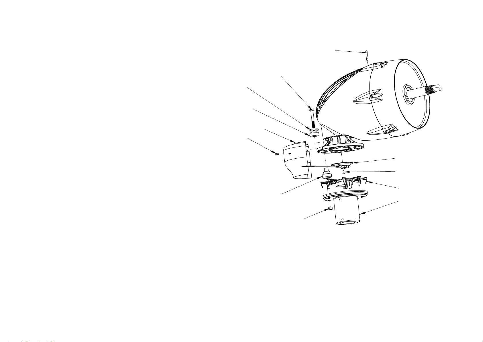
TIP: See exploded view on page 23.
Turbine Assembly on Pallet
• Includes: turbine, nosecone, blade hub, blade plate (screwed to pallet),
M42 hub mounting nut.
Blades (may be shipped separately)
• Blade mounting hardware
- M10 x 120, grade 10.9, hex head bolts (quantity 12)
- M10, grade 10.9, nut (quantity 12)
Nosecone mounting hardware
• M6 x 12 socket head screws, A2 stainless steel (quantity 3)
Skystream to Tower Mounting Hardware
• Vibration Isolators (quantity 8)
• Vibration Isolator Snubbing Washers (quantity 8)
• M12 x 90 hex head bolts, grade 10.9 (quantity 8)
• M12 nuts, grade 10.9 (quantity 8)
• M12 flat washers, A2 stainless steel (quantity 8)
Yaw Shield
• Yaw shield halves (quantity 2)
• M5 x 12 socket head screws (quantity 4)
Strain Relief Cover
• Cover with ground wire (quantity 1)
• M5 x 12 socket head screws (quantity 4)
Installation Personnel
Skystream Energy Europe recommends professional installation of Skystream.
While Skystream is not difficult to install, and many homeowners have successfully
installed their own Skystream, knowledge of local zoning and building code requirements, construction techniques, as well as residential electrical systems is required
for a safe installation.
Skystream dealers displaying the following insignia have completed factory training
on the correct and safe installation of Skystream.
Skystream Dealer
Miscellaneous
• RF antenna (quantity 1)
12 Skystream 3.7® Owner’s Manual, EU Edition, Rev B
Page 13
kilowat-hou
r
Transitio
n t
o large
r gauge wir
e i
f
40 A
G
GND
20 A
N
G
N
L1
G
N
L1
SPD
Skystream and panel
.
Optiona
l
+green)
N (blue)
N
G
other loads
L1
G
L1
N
G
N
GND (yellow
wir
e
GND
L1 (brown)
2-pol
e 3
0 A
, 240VA
C
L1
G
Tower groun
d
syste
m
Disconnec
t switc
h
Yaw groun
d
meter
Use onl
y coppe
r wir
e a
t the generator terminals
require
d due t
o distanc
e between
Aluminum wires may be used for home/utility
connection if transition is made in junction box.
14AWG wire must be copper only.
SPD = SURGE PROTECTIV
E DEVIC
E SUC
H A
S AL
IGHTNIN
G CURRENT ARRESTOR.
A
N APPROPRIATE
ARRESTO
R T
O SATISFY THE REQUIRE
D LIGHTNING
PROTECTIO
N LEVEL MUS
T B
E INSTALLED
.
SEE
LIGHTNING PROTECTIO
N SECTION O
F MANUA
L FOR
RECOMMENDATIONS
Fig. 1 Typical Skystream Installation
Note: Refer to Appendix A for detailed wiring drawings
Skystream 3.7® Owner’s Manual, EU Edition, Rev B 13
Page 14
Siting - Finding The Best Location For Skystream
75 m
6.5 m
Prevailing Wind
Local Requirements
The best location to install a wind turbine is often a compromise. Local building
restrictions, the height of surrounding structures, wire length, and available open
space may require Skystream be installed in a less than optimum location.
In general Skystream will produce more power if installed on a taller tower.
However, towers are expensive so it is important to balance performance (tower
height) to installed cost in order to achieve the lowest cost of energy and the
quickest payback.
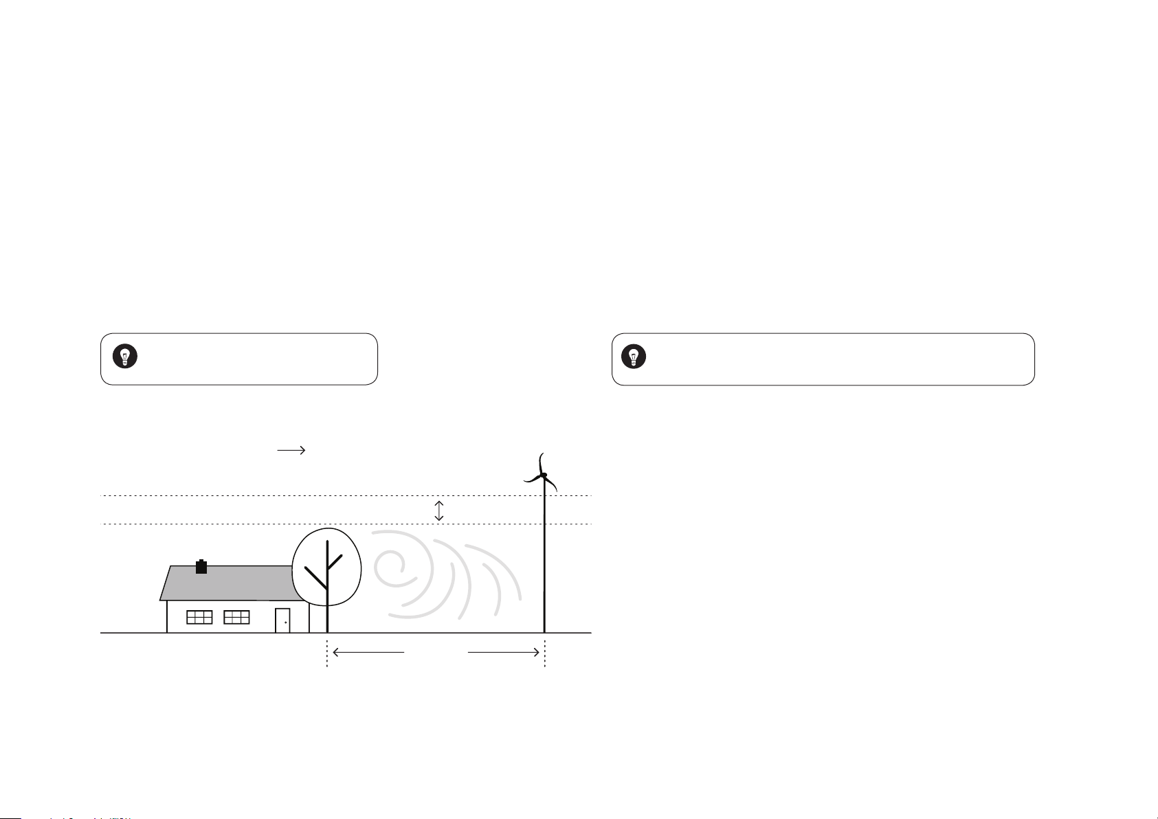
The General Rule: For optimal performance, install Skystream 6.5 m above any
surrounding object within a 75 m radius. See figure below.
TIP: Your dealer can help you determine the
best location for Skystream on your property.
Building codes and installation regulations may vary greatly depending upon
country, state, city and local townships. Be sure to obtain all the required
building permits BEFORE beginning installation. Make sure you understand
all inspection and installation requirements. Many locations may require
installation by licensed professional to meet building code requirements or to
qualify for rebate incentives.
Additionally, be sure to contact the local electrical utility company. Many utility
companies will require an “Interconnection Agreement” prior to installation.
Some utilities may also require installation of a separate power metre for
Skystream.
TIP: See our website: www.skystreamenergy.com for a sample interconnection
agreement that may be used by a utility yet to establish a program.
Optimal Skystream location.
14 Skystream 3.7® Owner’s Manual, EU Edition, Rev B
Page 15
INSTALLATION
Introduction
The following sections of this manual assume a tower and foundation appropriate for use with a Skystream are in place and ready for Skystream to be installed.
Southwest Windpower designed Skystream for easy installation by minimizing
the number of electrical connections. In most cases Skystream may be connected directly to the electrical utility panel. However, local requirements may
require installation of a disconnect switch and a second power meter between
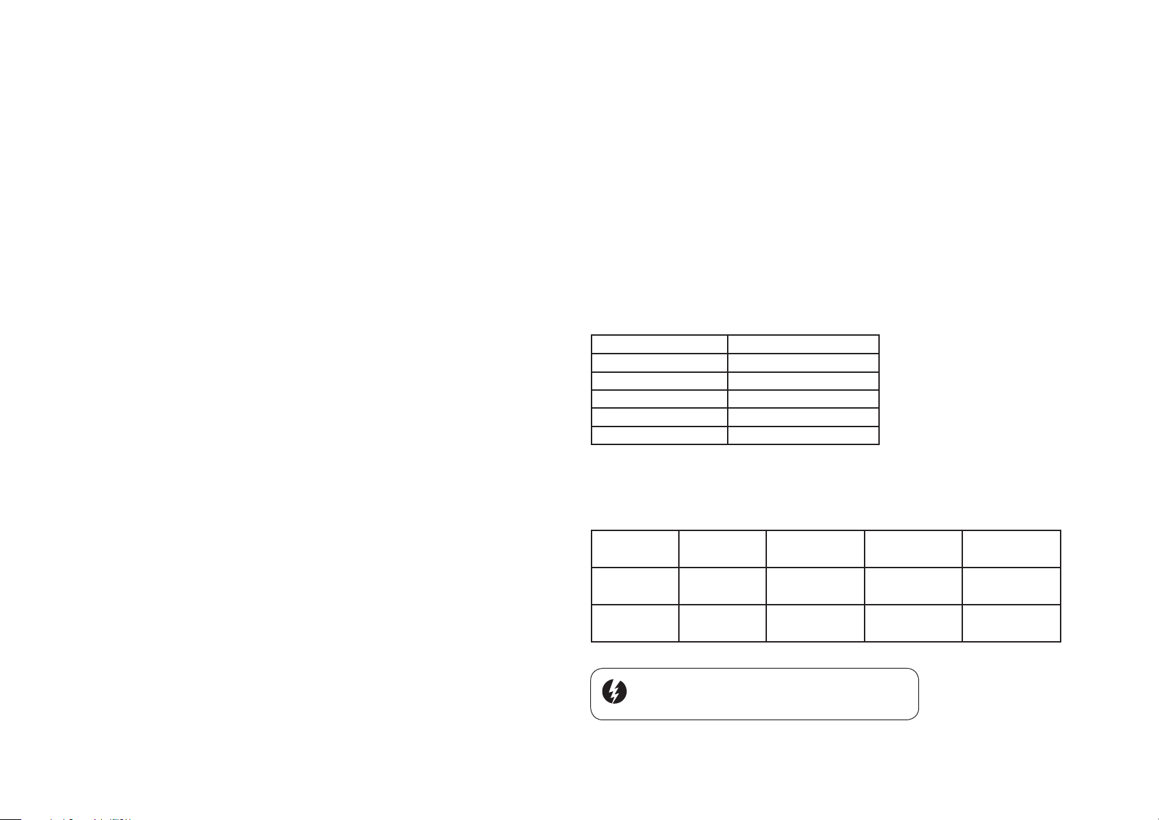
Skystream and the utility panel.
lations requiring a transition to 16 mm
2
(6 AWG) or 25 mm
2
(4 AWG) gauge wire.
Table 2 provides for a 25 m (82 ft) length of 10 mm2 (8 AWG) wire to be run
from the Skystream yaw to a disconnect switch box and a length of 16 mm2 (6
AWG) or 25 mm2 (4 AWG) gauge wire to be run from the disconnect switch box
to the utility panel. Select the appropriate wire size combination from Table 2
based on the of wire run length and Skystream voltage configuration.
Note if needed the 25 m (82 ft) length of 10 mm2 (8 AWG) wire may be shortened and the larger gauge wire lengthened a corresponding amount. However,
DO NOT lengthen the 10 mm2 (8 AWG) wire and also lengthen the larger gauge
wire as this will cause excessive resistance.
Wire Sizing
These wire sizing directions are for SINGLE Skysteam turbine installations which
are direct run to a main service panel.
DO NOT attempt to use these wire sizing instructions for a Skystream connected
to a sub-panel or for multiple Skystreams.
Note that the largest wire size that may be connected to the Skystream yaw terminals is 10 mm
2
(8 AWG) . For installations requiring a larger wire size (because
of distance) Southwest Windpower recommends using a disconnect switch box
installed between the tower and utility panel to transition to a larger wire size.
To determine the appropriate wire size measure the total distance from the
turbine to the electrical utility panel including the tower height and refer to the
tables on this page.
Table 1 includes maximum wire length information for wire sizes 10 mm2 (8
AWG) and smaller without transitioning to a larger wire size. Select the appropriate wire size based on the total wire length and Skystream voltage configuration
(230 VAC, single phase).
If the required wire length is greater than can be accomplished with 10 mm2 (8
AWG) wire refer to Table 2. This table includes wire size information for instal-
Table 1
Wire Size 230 VAC, Single Phase
25 mm2 (4 AWG) See Table 2
16 mm2 (6 AWG) See Table 2
10 mm2 (8 AWG) 85 m (278 ft)
6 mm2 (10 AWG) 53 m (174 ft)
4 mm2 (12 AWG) 34 m (110 ft)
Use copper conductors only - Minimum wire temperature rating is 75° C (167° F). Distances
and wire sizes are based on 2400 W power production and maximum 2% voltage rise at
the turbine.
Table 2
System Voltage Maximum Wire
230 VAC, Single
Phase
230 VAC, Single
Phase
Warning: For your safety, make sure power is turned off
before working on any and all electrical connections.
Length
176 m (577 ft) 25 m (82 ft) -------------- 151 m (495 ft)
120 m (394 ft) 25 m (82 ft) 95 m (312 ft) --------------
10 mm2
(8 AWG)
16 mm2
(6 AWG)
25 mm2
(4 AWG)
Skystream 3.7® Owner’s Manual, EU Edition, Rev B 15
Page 16
Grounding
Utility Panel Connections
All electrical systems must be grounded in accordance with local and national
standards. Grounding provides protection from electrical shock, voltage surges
and static charge build up.
The figures in Appendix A provide information for grounding the tower and
Skystream at the service panel by means of the ground lead coming from the
yaw terminals of the turbine.
Appendix B provides information for grounding the tower according to the
National Electric Code (USA) and IEC 60364-5-54. Information about grounding electrodes, grounding conductors, and connections is provided.
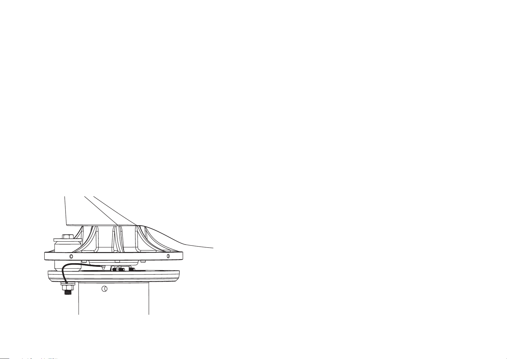
The turbine must be grounded to the tower as depicted below.
Note: The AC output neutral is NOT bonded to ground within Skystream. The
AC neutral is bonded to ground at the AC service panel.
The instructions in this section and Appendix A are provided as reference, local
electrical codes and standards have precedence over these instructions.
Skystream connects directly into your electrical panel. Wiring will vary with local
zoning authority and utility. Refer to Appendix A for drawings for each voltage,
frequency and phase configuration. Some installations will require a visible lockable disconnect switch located next to the electrical metre and/or at the base
of the tower. The disconnect switch is utilized by your local utility in the event of
a power outage to ensure no voltage is placed on the utility line during repair.
Again, it is extremely important to install in accordance with local and national
zoning regulations.
Note: Only 20 Amp circuit breakers may be used to connect Skystream to AC
service panel. Refer to wiring diagrams in Appendix A.
Fig. 2 Proper grounding
of the yaw connection
16 Skystream 3.7® Owner’s Manual, EU Edition, Rev B
Page 17
Electrical Connections To Skystream
CAUTION – Be sure power is turned off when making electrical connections.
The following section provides directions for completing the main power connections to the Skystream yaw assembly. The connections are most easily
accomplished with Skystream on the ground as would be the case when utilizing a tilt up tower.
If the installation does not incorporate a tilt up tower, the connections may
still be made on the ground by utilizing a sufficient length of cable to connect
Skystream to the nearest junction point. If, for example, an electrical disconnect box will be installed at the base of the tower, connect enough cable to
Skystream to make the connections at the disconnect box – leave some extra
cable for connections. The wire connections can then be made on the ground,
Skystream hoisted to the top of the tower and the cable “lowered” down the
tower and Skysteam bolted to the tower.
l
Position Skystream on its side to access the wire terminals.
l
Remove approximately 5 cm of protective sheathing from cable and strip
approximately 1 cm of insulation off wire leads.
l
Note the maximum wire size that can be connected directly to Skystream
is #6 Metric Wire Size or #8 AWG. Refer to Wire Sizing Section of this
manual for instructions on selecting correct size wire.
l
Pass cable through strain relief cover so approximately 2.5 cm of cable
sheath protrudes through the cover.
l
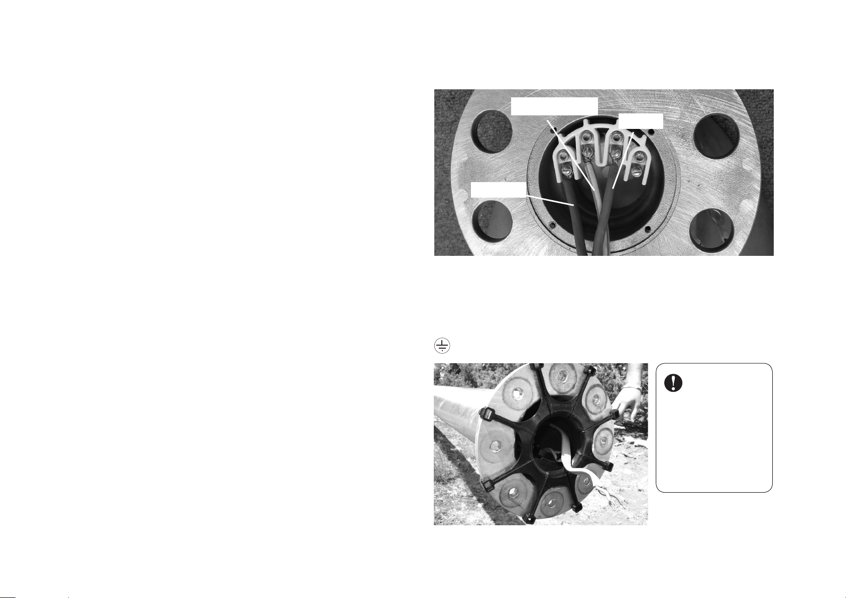
230 V, 50 Hz, 1 Phase systems: Connect the brown, blue and green/
yellow wires to the matching corresponding color coded terminals on
Skystream yaw. There is no wire connection to bare yaw terminal as shown in Fig
3. Tighten wire terminal screws to 2.3-2.5 N-m.
G: Yellow/Green
N: Blue
L1: Brown
Fig. 3 Wire run to the yaw connection (230V, 50Hz, single phase).
Wiring Symbol Definitions - 230 V, 50 Hz, Single Phase Systems
L1 = Line 1, AC Line Voltage, Brown Wire (230V, 50 Hz, systems)
N = AC Neutral, Blue Wire, (230V, 50 Hz, systems)
G = Gnd. = AC Ground, Green/Yellow Wire
Indicates AC Ground
IMPORTANT: Install
the Skylevel “spider”
on the tower top
prior to connecting
the power wires to
Skystream yaw. The
wires must pass
through center of
“spider” as shown in
accompanying photograph.
Skylevel “spider”
Skystream 3.7® Owner’s Manual, EU Edition, Rev B 17
Page 18
l
With power still on, wait approximately 5 minutes and attempt to rotate
main blade shaft; blade should be noticeably easier to turn than with
power off.
l
Turn off power and verify that Skystream has returned to its “braked”
mode. If Skystream fails this test check connections and repeat test
– test MUST be passed before proceeding.
l
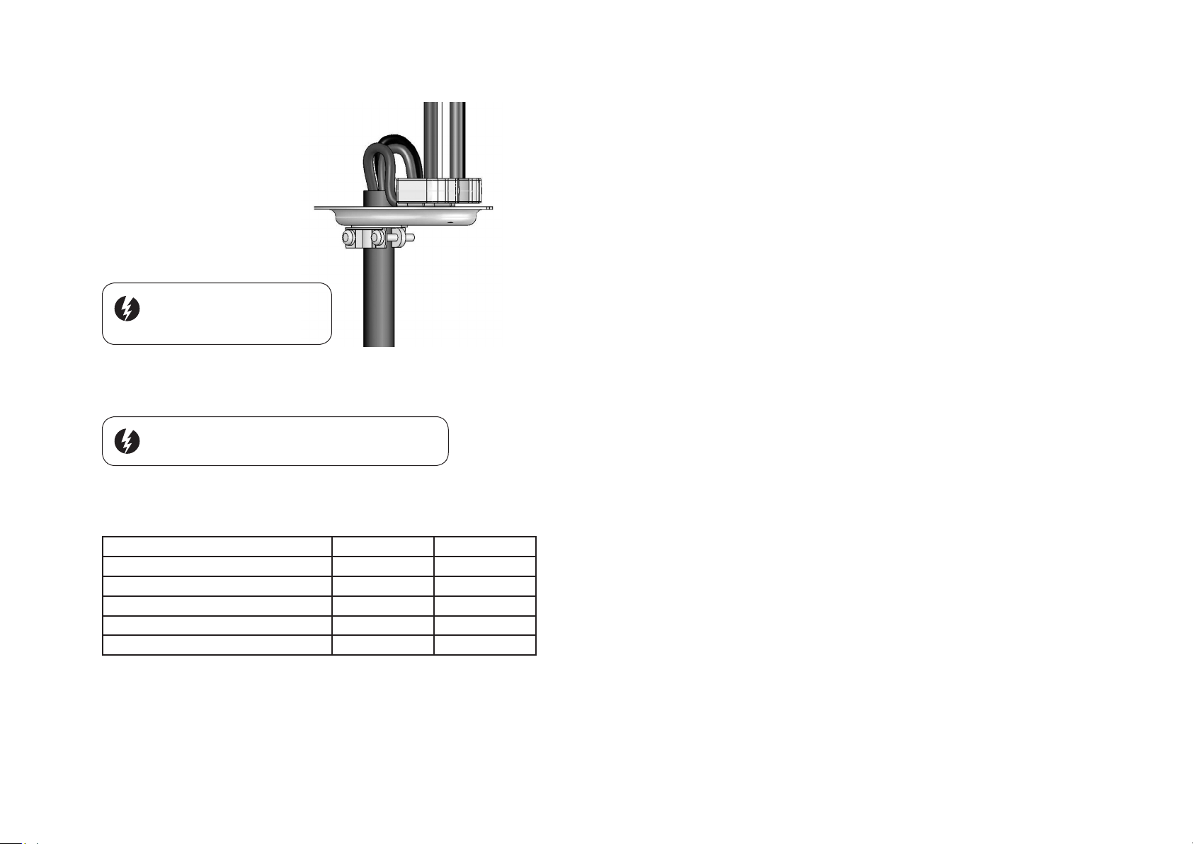
With power turned off position the wires as depicted in accompanying
figure and secure strain relief cover using four M5-0.8 x 12 socket
head screws. Tighten strain relief clamp to secure cable.
Caution: Make sure AC power is
switched “OFF” before proceeding
with installation.
Yaw wire
Caution: Electrical Shock Hazard - use extreme care when
making electrical measurements on live electrical systems.
After making connections, turn on power and measure voltages at
terminals. See table below:
L1 - N L1 –L2
120 / 240 VAC, 60 Hz, Split Phase
120 / 208 VAC, 60 Hz, 3 Phase
230 VAC, 50 Hz, 1 Phase
120 VAC, 60 Hz, 1 Phase
127/220 VAC, 60 Hz, 3 Phase
120 VAC 240 VAC
120 VAC 208 VAC
230 VAC
120 VAC
127 VAC 220 VAC
---------
---------
Lightning Protection
The Skystream 3.7 turbine is designed to withstand over voltages and surge
currents (6kV, 3kA, 8/20µs) caused by INDIRECT lightning strikes or switching operations according to the Standard for Interconnecting Distributed
Resources with Electric Power Systems (IEEE 1547) . For this protection to
be effective, it is necessary to ensure that over voltages at the Skystream
conection terminals will not be higher than the above values of the surge test.
To provide this over voltage protection against DIRECT lightning strikes;
a Type 1 lightning current arrestor, that reduces over voltages to a level
below 6 kV but is capable of discharging very high currents, much larger
than those handled by surge protective devices present inside Skystream is
required.
Note: Refer to Appendix C for specific instructions on the selection of a
Lightning Protection System.
18 Skystream 3.7® Owner’s Manual, EU Edition, Rev B
Page 19
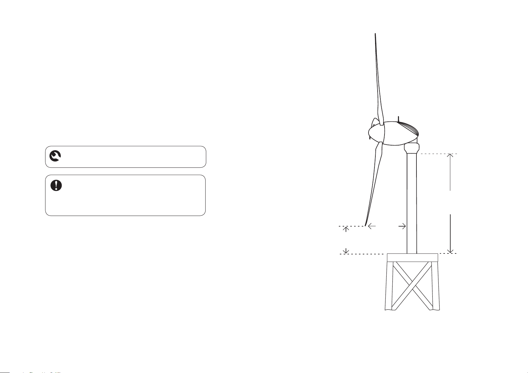
46 cm
30 cm
Stub tower
Not to exceed
213 cm
Installing Skystream on a Tower
There are several types of towers that can be used with Skystream. It is essential that
Skystream is installed on a properly engineered tower. One of the leading causes of wind
generator failure is use on a poorly designed tower.
Regardless of the tower design and height you select, there are two critical areas that
must be considered when selecting the tower. These are the stub tower height and blade
clearance, refer to accompanying figure.
Note: The orientation of the vibration isolators is very important. Refer to Figs. 4, 5 & 6.
Warning: Working on towers is dangerous and should be left
to professionals with proper safety equipment and training.
IMPORTANT: Skystream Energy Europe’s Warranty is only
extended to installations that are made on a properly engineered tower. Skystream Energy Europe reserves the right to
deny any warranty claim in which an improperly designed tower
is used.
Critical turbine blade clearances
Skystream 3.7® Owner’s Manual, EU Edition, Rev B 19
Page 20
Bolting Skystream to the Tower
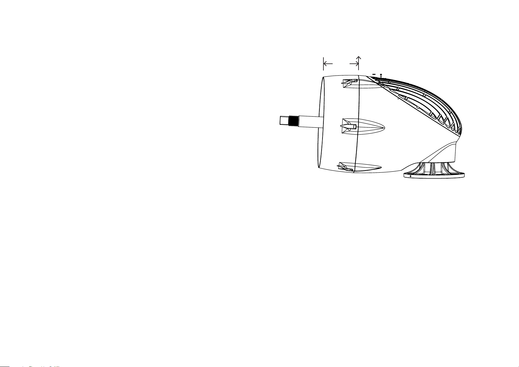
CG
The following section provides directions for bolting Skystream to the tower. Before
Skystream is bolted to the tower complete the electrical connections as described in the
“ELECTRICAL CONNECTIONS” section of this manual. Bolting Skystream to the tower
is most easily accomplished at ground level as in the case with a tilt-up tower. Alternately
Skystream may be bolted to the tower on the ground, and the tower with Skystream
hoisted into position as an assembly; or Skystream may be hoisted to an already erected
tower. These latter two options require specialized equipment and training and should
only be attempted by trained professionals.
• Install the vibration isolator halves (items 4 and 5) on the yaw as shown in Fig. 6.
Note the orientation of the isolator halves is very important – install as shown.
• Insert the vibration isolator bolts and snubbing washers into the vibration isolators from
“above” as shown in Fig. 6.
• Using an appropriate lifting device, lift Skystream and align vibration isolator bolts with
holes in the tower flange.
Note: A wide nylon lifting strap may be used to hoist Skystream into position. The strap
MUST cinch or “choke” the turbine tightly prior to hoisting. Refer to the accompanying
figure for positioning the strap along the centre of gravity.
18 cm
Centre of gravity
20 Skystream 3.7® Owner’s Manual, EU Edition, Rev B
Page 21
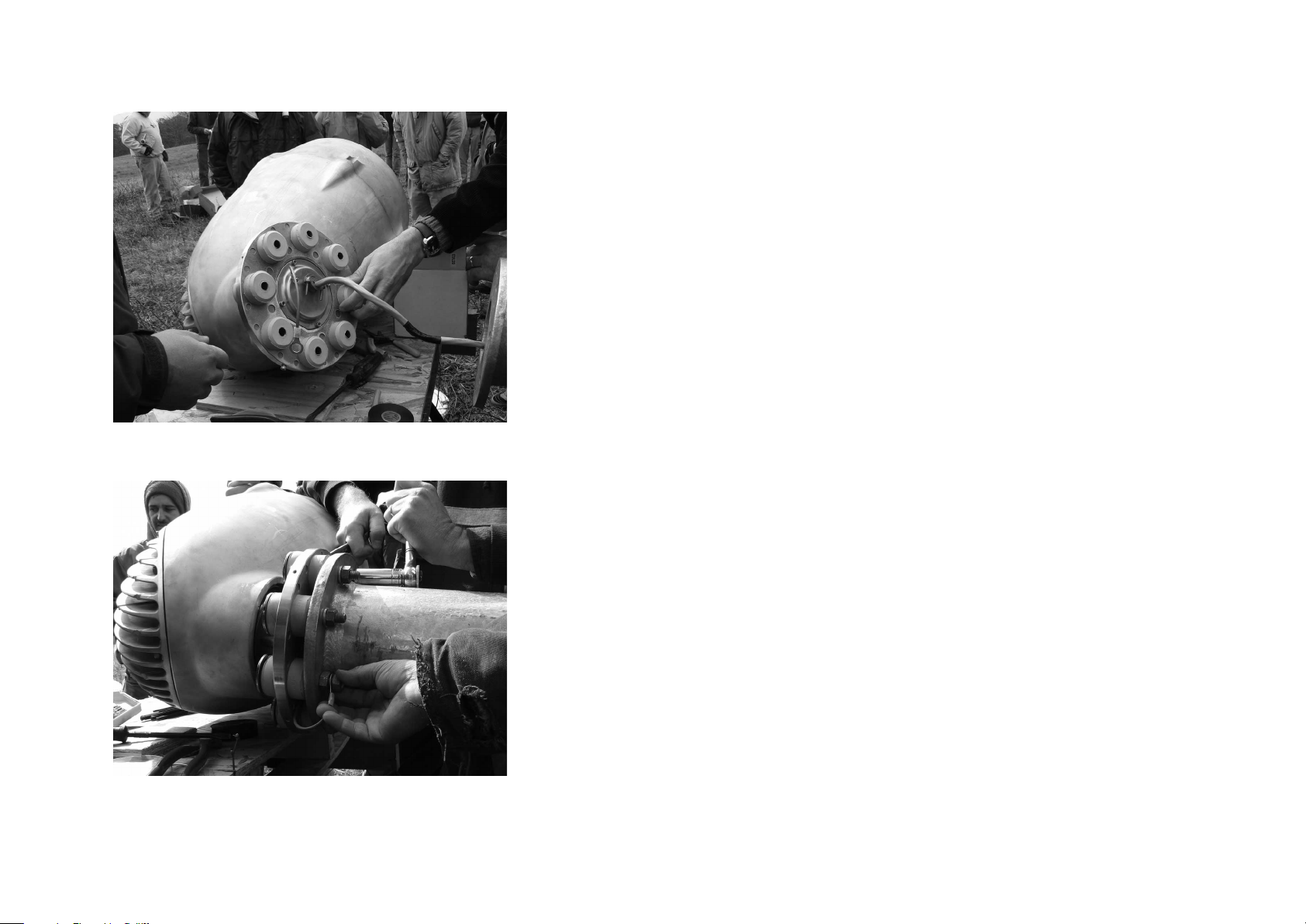
Fig. 4 Placing vibration isolators
• Install nuts on bolts to secure Skystream to the tower.
• Connect the turbine ground wire as depicted in Fig. 2. The turbine MUST be grounded to the tower
as shown.
• Torque the vibration isolator bolts to 80 N-m in two steps. First torque all bolts to 55 N-m then
tighten all bolts to 80 N-m.
• Mount the yaw shield halves using four M5 socket head screws. Refer to Fig. 6.
Fig. 5 Grounding turbine to tower
Skystream 3.7® Owner’s Manual, EU Edition, Rev B 21
Page 22
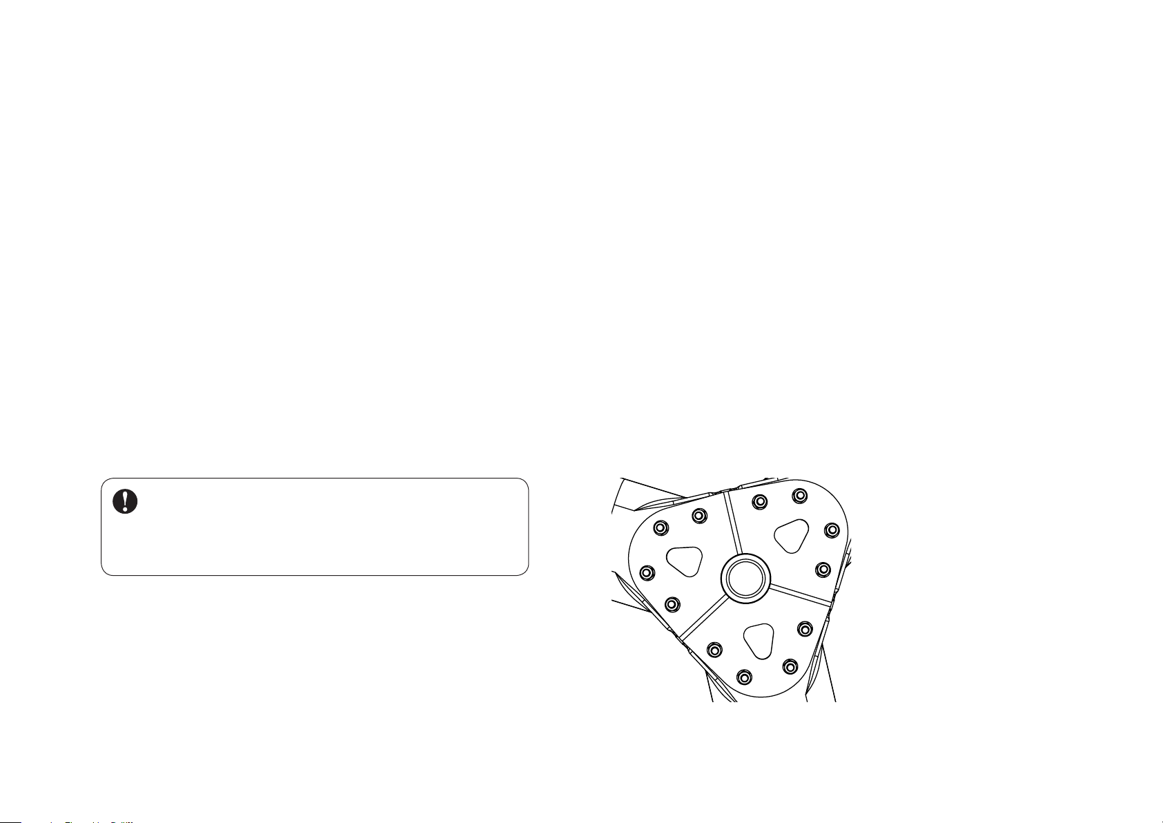
Installing the Blades (Hub Not on Turbine) Bolt Tightening Sequence
Proper installation of the blades is critical for safe operation. The blade nuts and
bolts are a unique grade of steel and are specially coated to prevent corrosion.
DO NOT substitute different nuts and bolts. Spare nuts and bolts are provided
with Skystream.
Carefully follow these instructions to obtain secure bolted joints and maximum
corrosion protection, particularly in corrosive marine environments.
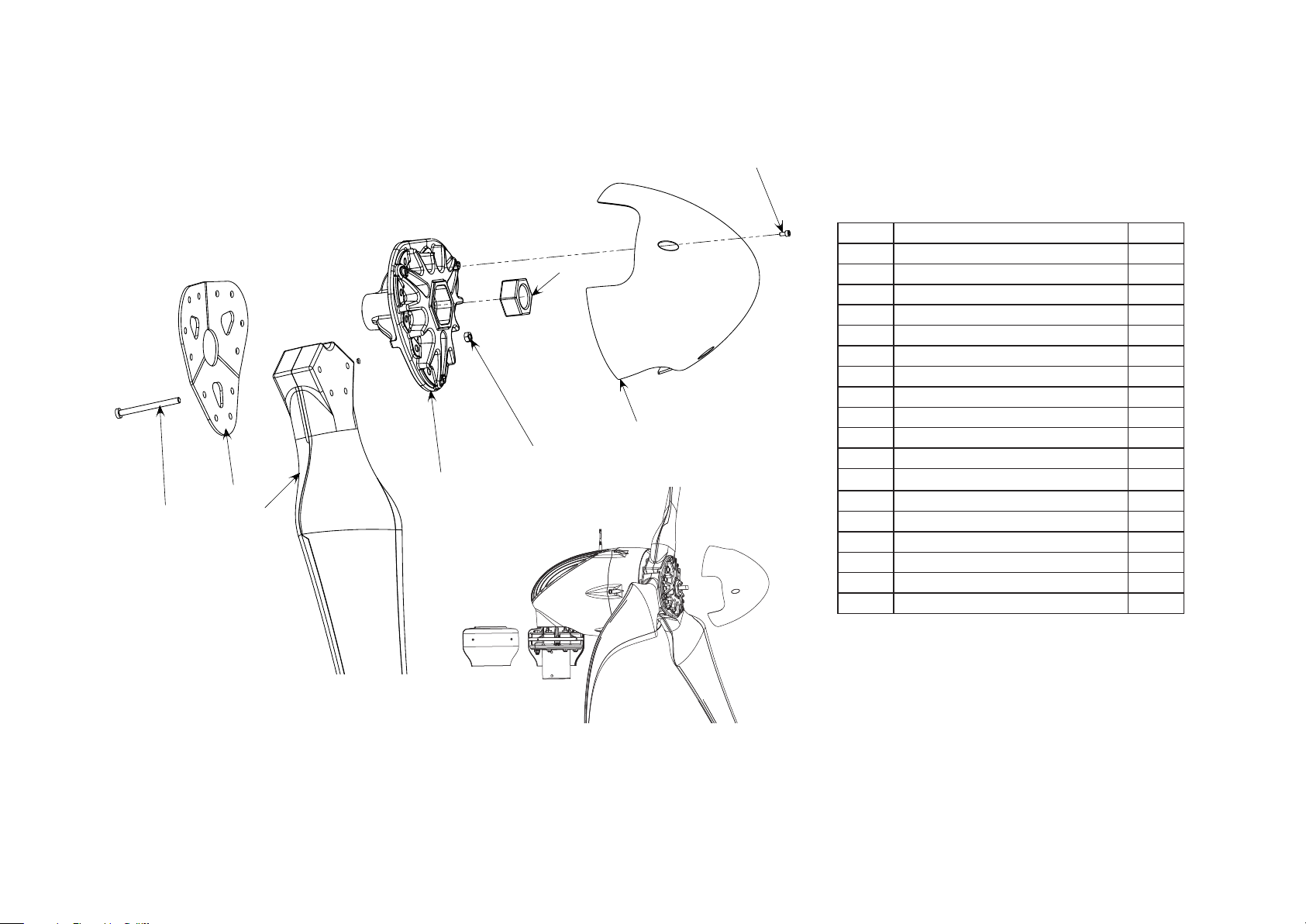
l
Start the assembly by positioning a blade between the blade hub and blade
plate. The blades may only be installed in one position due to the triangular
boss cast into one side of the blade root.
l
Install the bolts by passing the bolt through the BLADE PLATE and AWAY
from the NACELLE as shown in Fig 7.
l
Leave the nuts loose until all blades are installed and then tighten the bolts
just enough to clamp the blades between the hub and plate.
IMPORTANT:
• Do NOT substitute nuts, bolts or washers. Contact SWWP for replacements.
• DO NOT apply lubricants to nut or bolt threads.
• RECHECK bolt torque after tightening bolts.
l
Torque the blade bolts to 68 N·m in two stages.
l
Following the Blade Bolt Tightening Sequence shown – torque each bolt to
41 N·m in two stages.
l
After completing first stage, following the Blade Bolt Tightening Sequence,
and tighten each bolt to 68 N·m.
l
After completing the second tightening stage RECHECK each bolt is tight-
ened to 68 N·m.
l
The blades are now assembled to the hub and ready for installation onto the
turbine rotor shaft.
l
Coat the inside diameter of the blade hub with a multipurpose lithium grease
to prevent corrosion between the hub and shaft.
l
Position the hub nut in the centre of the blade hub and slide the entire hub
/ blade assembly onto the shaft and “spin” the entire assembly to screw the
hub onto the shaft.
l
Tighten the blade hub assembly to 270 N·m by holding the blades and using
the “flats” on the rotor shaft.
2
3
11
1
12
22 Skystream 3.7® Owner’s Manual, EU Edition, Rev B
10
4
9
8
7
5
6
Blade bolt tightening
sequence
Page 23
5
14
13
1
2
3
4
8
7
6
8
11
Installing the Nosecone and Antenna
l
Install the nosecone with three M6-1.0 socket head bolts.
l
Install RF Antenna on matching fitting on top of Skystream. Fingertight
is sufficient.
Important: Do Not Forget to Install RF Antenna
Do not forget to install the RF antenna. Skystream is equipped with an on-board
radio that may be used to monitor its performance via the Skyview Interface.
Additionally, service personnel may use the radio to diagnose, troubleshoot or
upgrade your Skystream without removing it from the tower.
Final Electrical Tests (Tilt-Up Towers)
At this point Skystream should be bolted to the tower and all the ancillary equipment – blades, nosecone, yaw shield, and antenna – attached.
Prior to tilting the tower into position, the following final electrical tests should be
performed:
l
With power turned off attempt to rotate the blades – there should be noticeable
resistance although the leverage provided by the blade will make it possible to
rotate the blades.
l
Turn on power and attempt to rotate the blades after approximately 5 minutes.
There should be noticeably less resistance required to rotate the blades.
l
Turn off the power and verify that Skystream returns to a “braked” condition.
l
Verify Skystream is grounded to the tower by measuring the resistance
Fig. 6 Yaw and
antenna assembly
between the nacelle (use an unpainted bolt head in the case of
marine units) and the tower flange. The resistance must = < 1 ohm.
Do not attempt to put Skystream into service until these tests pass. If tests pass,
tower may be tilted into position and placed into service.
Skystream 3.7® Owner’s Manual, EU Edition, Rev B 23
Page 24
17
19
21
20
24
18
23
22
# DE SCRIPTION QTY.
1 R F Antenna 1
2 M12 x 1.75 x 90mm Hex Bolt Grade 10.9 8
3 Snubbing Washer 8
4, 5 Vibration Isolation Ring (4) and Bushing (5) 8
6 Strain Relief Cover Assembly 1
7 Yaw Shield 2
8 M5 x 12mm Socket Head Screw 8
11 Skylevel Assy. 1
13 M12 x 1.75 Nut grade 10.9 8
14 5” Tower Insert (optional) 1
17 Blade Plate 1
18 Blade 3
19 Blade Hub 1
20 Hex head bolt, M10, grade 10.9 24
21 Hex nut, M10, grade 10.9 12
22 Nosecone 1
23 Hub Retaining Nut grade 10.9 1
24 M6 x 1 x 12mm Bolt SHCS grade 8.8 3
Fig. 7 Blade and
nosecone assembly
Fig. 8 Completed assembly
24 Skystream 3.7® Owner’s Manual, EU Edition, Rev B
Page 25
OPERATION AND ADJUSTMENTS
--
9/30/06
ECO#1012
NC
REVISIONS
REV.
DESCRIPTION
DATE
APPROVED
Manual Operation of Skystream
Manual operation of Skystream is limited to starting and stopping using the
circuit breakers at the electrical utility panel or electrical disconnect switch if
equipped. To stop Skystream, switch the circuit breakers to “OFF” and to restart
Skystream switch the circuit breakers to “ON”. Note that Skystream may require
approximately 5 minutes to restart after the circuit breaker is switched “ON”.
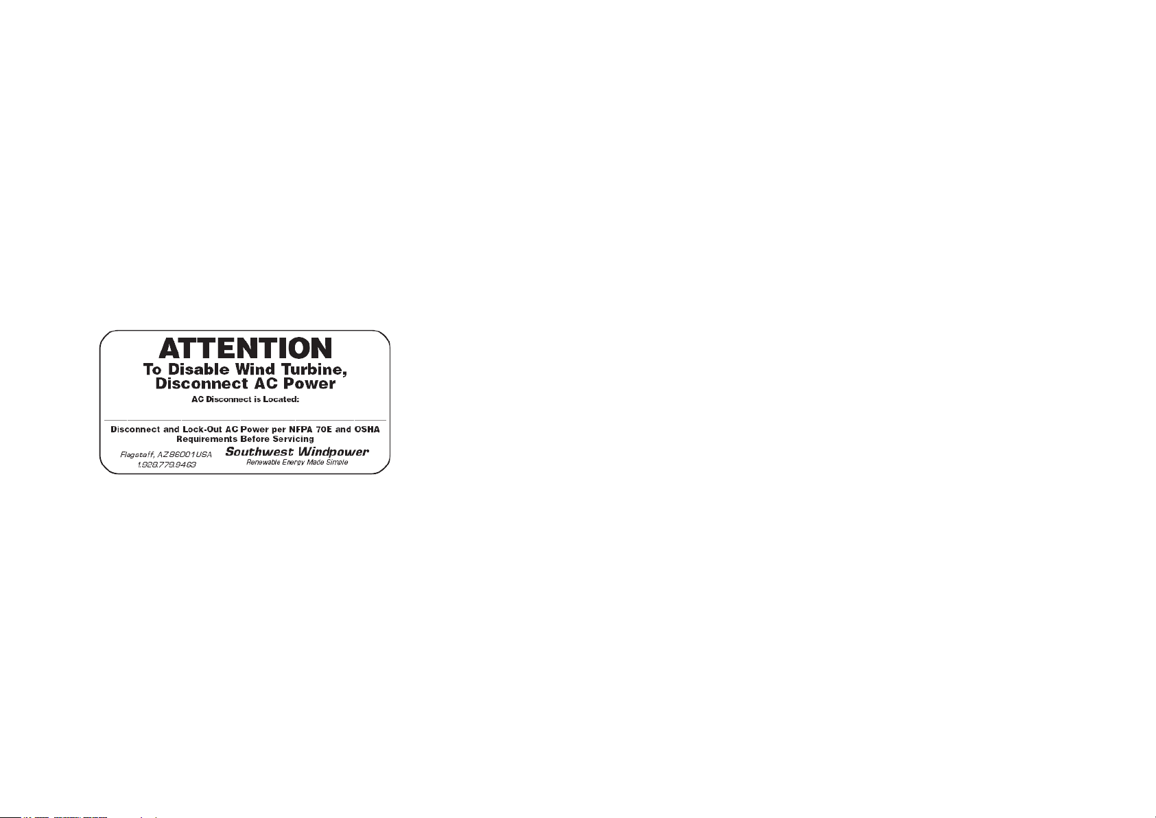
An “ATTENTION” label, depicted below, is provided to indicate the location of the
AC power disconnect switch or circuit breakers. Apply the label in a prominent
location where it will be seen by operators or service personnel.
Adjustments
Adjustments to Skystream are limited to setting the elevation. As delivered,
Skystream is configured for operation up 1000 m above sea level. There is no
need to reset the elevation unless Skystream is installed above that elevation.
The elevation may be reset using the optional remote display. If a remote display
is unavailable to you, contact your Skystream dealer about resetting the elevation.
Maintenance
After 20 years of service the blades MUST be replaced – even if there
is not apparent damage. The blades should be replaced as a set. Do not
attempt to replace individual blades. All blade mounting hardware – bolts, nuts
and washers – should be replaced at the same time. Do NOT attempt to reuse
the blade fasteners.
There are no periodic service requirements other than replacing the blades after
20 years. All bearings and rotating components were designed for a 20 year
life at an IEC Wind Class II site, under the IEC 61400-2 Small Wind Safety
Standard. This corresponds to a site with an average wind speed of 8.5 m/s.
Although there are no routine service or maintenance requirements, Skystream
owners should be observant of any unusual sounds, vibrations or erratic behavior.
If unusual behavior is noticed the best course of action is usually to shut down
the turbine down and contact the dealer or service centre.
One area of Skystream that may experience damage are the blades, for example
from flying debris during a high wind storm. For this reason Skystream Energy
Europe recommends Skystream be shut down on an annual basis and an
inspection of the blades performed. The inspection may be accomplished using
binoculars or by close visual inspection. Inspect for cracks and chips particularly
along the edges of the blades. Any damage is cause for replacing the blades. If
in doubt contact your local service centre.
Skystream 3.7® Owner’s Manual, EU Edition, Rev B 25
Page 26
In the event you must gain access to Skystream use the opportunity to
perform the following inspections:
• Remove the yaw shield, and wipe off any grease that may have
seeped from the yaw bearing.
• Check hatch cover bolts are tight, Bolts should be tightened to 7 N·m.
• Verify the yaw bearing snap ring is still properly seated in the snap
ring groove within the nacelle. (this is the snap ring located just
below the yaw bearing).
• Check the tightness of the (8) yaw bolts with a torque wrench. All
yaw bolts should be torqued to 80 N·m.
• Reinstall the yaw shield and secure the fasteners.
• Check tightness of blade bolts with torque wrench. All blade bolts
should be torqued to 68 N·m.
• Clean the rotor blades with a mild soap and water. Remove as much
of the dead bug matter as possible from the blades.
• Look for any problems with the blades such as cracks, or damage to
the edges of the rotor blade.
• Inspect the face, nacelle, and the rest of the Skystream and note any
potential damage or problem.
Troubleshooting
Without the optional wireless “Skyview Interface Kit”, troubleshooting Skystream
is limited to checking the Skystream connections to the utility grid. Check the
connections as “close” to Skystream as possible, depending on the installation
this may be at the utility panel or at a disconnect switch. The connections may
also be checked at yaw terminals (see Electrical Connections Section in this
manual), however, this will require removing Skystream from the tower.
Using the Skyview Interface Kit this voltage and additional troubleshooting information may be accessed without the need to remove the turbine. Contact your
local dealer or Skystream Energy Europe Technical Service.
Emergency Shutdown
If Skystream’s internal microprocessor determines a serious internal fault has
occurred it will execute an Emergency Stop – and E-Stop. An E-Stop will only
take place if the fault is severe and requires servicing Skystreams internal components. Refer to the Key Operating Characteristics section of this manual for
a complete description of the Skystreams various “shut down” modes including
Emergency Stops.
Resetting an Emergency Stop requires special equipment and can only be
accomplished a trained technician. If you suspect your Skystream has executed
an Emergency Stop contact Skystream Technical Support.
Service
The internal components of Skystream should only be serviced by qualified
technicians specifically trained to perform the service. Under no circumstances
should untrained technicians attempt to perform service or repairs unless under
the direct guidance of a trained technician.
Service operations that were performed during the installation of Skystream, for
example bolting on the blades or bolting Skystream to the tower may be performed as necessary by the user / operator.
26 Skystream 3.7® Owner’s Manual, EU Edition, Rev B
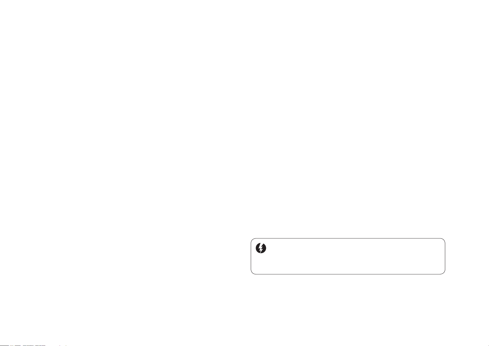
Warning: There is risk of electric shock from both AC and DC voltages within
Skystream. Do not attempt to remove the hatchcover to access the internal components. AC power should always be disconnected, the turbine restrained from yawing,
and blades secured from rotating prior to servicing or serious or fatal injury may occur.
Page 27

KEY OPERATING CHARACTERISTICS
The Skystream 3.7 operates by converting the kinetic energy of the wind into
rotational motion that turns an alternator and ultimately produces usable electric
power. In actuality this is a great over simplification of Skystream’s operation
since it must very precisely match the frequency and voltage of the electricity
supplied by the local utility company in order to power your home and its appliances. Additionally, Skystream monitors and adjusts its performance to provide
safe operation and extract the maximum energy from even low speed winds.
Skystream will begin producing power in a wind of approximately 3.5 m/sec. At
that speed the blades will rotate at approximately 120 rpm. Once it has started
producing power, it will continue to produce power at lower speeds down to 80
rpm and less than 3 m/s. As the wind speed increases the blade speed will also
increase. At about 9 m/s the blades achieves a rotational speed of 330 rpm.
This is Skystream’s rated speed. Should the wind speed increase above 9 m/s
the blade speed will remain essentially fixed at 330 rpm. If a condition occurs
that causes the rotational speed to exceed 360 rpm, Skystream will shut down
for approximately 10 minutes after which it will resume normal operation unless
a fault is detected causing it to remain shut down. This is an unlikely scenario
that should never occur in normal operation. It is important to set the elevation
for the turbine to operate correctly. If it is not set, the turbine may experience
premature shut downs.
If a wind gust exceeds 25 m/s, then the Skystream will shutdown for 1 hour.
After 1 hour, the Skystream will turn back on, and resume normal charging. If the
wind is still above 25 m/s, then the Skystream will shutdown for another hour.
In addition to adjusting its operation in response to wind conditions Skystream
also monitors the electrical utility grid and its own internal health. Should the
electric utility voltage or frequency differ from Skystream’s voltage, for example
due to a power failure, Skystream will disconnect from the grid and enter a
“braked mode”. While in this mode the blades are held stationary while the
Skystream monitors the utility power. If Skystream determines that the power
has returned to within specification, it will re-connect to the grid and resume
normal operation. This is the same cycle that occurs when Skystream is initially
powered.
Additionally, should Skystream determine an internal fault exists it will execute
an emergency shutdown – an E-stop. An E-stop will only take place if a severe
fault that requires servicing internal components has occurred. For that reason
resetting an E-stop requires gaining access to the interior of Skystream. It cannot be reset from the ground.
Electronic Stall Regulation
The Skystream 3.7 has the ability to adjust the rotational speed of its blades or
even stop the blades if required by ambient conditions. This referred to as Stall
Control and it is accomplished by adjusting the current draw from the alternator. The higher the current draw the greater the electromagnetic torque applied
to the rotor and if enough torque is applied the blades will slow or even stop. In
simple terms the inverter is demanding more power than the available wind can
provide thus causing the blade rotational speed to decrease.
As a safety feature the alternator is capable of producing approximately five
times the torque required to control the turbine. This extra available power
means that even if segments of the alternator windings are damaged there is
still sufficient torque to stop the turbine.
While Skystream is connected to the utility grid it constantly monitors that
all conditions, for example grid voltage and frequency, are within limits. If the
inverter determines that all operating conditions are within limits, it opens three
Normally Closed (NC) relays, RL1, 2 and 3, removing the short from the alternator windings and allowing the blades to spin freely.
Skystream 3.7® Owner’s Manual, EU Edition, Rev B 27
Page 28
Only then will it operate the DPDT Grid Relay RL_G to allow the inverter to
export power to the grid. Refer to the Skystream Block Diagram in Appendix A.
Should the inverter sense an abnormal condition, for example high current in the
alternator windings by means of the current sensors on the relay board, it will
close relays RL1, 2, and 3 thereby stopping the turbine. In turn, the DPDT Relay
RL_G will be operated to the position where the inverter power exporting circuitry is disconnected from the grid.
Disposal of Skystream
This symbol shown on Skystream or its packaging
indicates it may not be treated as household waste.
Dispose of Skystream properly by handing the
entire turbine assembly over to the applicable collection point for recycling of electrical equipment.
Redundant Relay Switch Control
As a redundant measure of safety to guarantee stopping the turbine in case of a
winding fault or a lost connection to the alternator, there are seven connections
to the alternator windings, but only three are necessary to control or stop the
turbine. And as a final measure of safety, if the inverter is unable to control the
rotational speed and Skystream exceeds approximately 400 rpm, the rectified
voltage will exceed the Zener (Z) voltage on the relay board, causing the latching relay (RL4) to open. This will cause the relays RL1, 2, and 3 to close and
apply all the available electromechanical torque to the rotor, stopping Skystream
completely. The inverter power path will also be disconnected from the grid by
means of relay RL_G. This is the final level of control and is only applied when
all other methods of control have failed. As such, once set, (latched) RL4 may
only be reset by gaining internal access to Skystream – it cannot be reset via
the Remote Display.
Warning: Power to Skystream MUST BE
TURNED OFF prior to servicing
By ensuring Skystream is disposed of correctly,
you will help prevent harm to the environment,
which may be caused by inappropriate disposal of
this product. The recycling of materials will help
conserve natural resources. For more detailed
information about recycling of Skystream, please contact your local waste disposal authorities, your household waste disposal service or the store where you
purchased Skystream.
Skystream was manufactured in compliance with the Restriction of Certain
Hazardous Substances in Electrical and Electronic Equipment 2002/95/EC
(RoHS) and therefore does not contain any of the materials regulated by that
standard.
28 Skystream 3.7® Owner’s Manual, EU Edition, Rev B
Page 29

Frequently Asked Questions
1) What happens if I lose power from my utility company?
If there is a power outage the Skystream will shut down within one second. It will
resume normal operation when power is restored. There are many safety requirements of a utility-tied inverter. The Skystream meets all of these requirements
per UL 1741, IEEE 1547 and appropriate European Regulations.
2) Does the Skystream have lightning protection?
Yes, the Skystream has lightning protection. The Skystream can handle
6000 Volts as required by UL 1741, IEEE 1547 and appropriate European
Regulations. If you live in a lightning prone area Skystream Energy Europe recommends an additional lightning arrestor at the base of the tower.
3) What should I do if I’m expecting a severe storm?
The Skystream is designed for very high winds, but it is always a good idea to
shut Skystream down if there is going to be a severe storm to protect against
any flying debris.
4) How do I shut down Skystream?
To turn off Skystream all you need to do is turn off the breaker Skystream is
connected to. This will cause NO damage to the unit.
7) When should I contact an authorized service technician?
a. If there is any unusual vibration coming from Skystream.
b. If you hear any noise that sounds like mechanical interference.
c. If the Skystream is connected to the utility power (i.e. all breakers and dis-
connects are turned on), the wind is blowing, but the Skystream is not turning very fast.
8) Can I mount Skystream to my roof?
Roof and building mount is not recommended. Because of the size and weight
of the wind generator, Skystream needs to be mounted on a PE certified tower
to ensure the quietest and safest system. Roof mounting will invalidate the warranty.
5) Can I leave Skystream unattended?
Yes, the Skystream is designed to operate without any user input. If there is any
fault it will shut down on its own.
6) What do I do if Skystream is facing upwind even though there is a strong wind?
If the Skystream is not tracking correctly, you should check to see if the tower is
level.
Skystream 3.7® Owner’s Manual, EU Edition, Rev B 29
Page 30

Page 31
APPENDIX A: ELECTRICAL DIAGRAM
Skystream Energy Europe GmbH
A wholly-owned subsidiary of Southwest Windpower, Inc.
Mannesmannstr. 6
50996 Cologne
Germany
Tel: +49 (0) 221 16 53 94 50
[email protected]
www.skystreamenergy.eu
No vembe r 2010 Sky st ream Energy Eur op e
All Rights Reserved
Page 32

Skystream 3.7® Owner’s Manual
Appendix A: Electrical Diagram
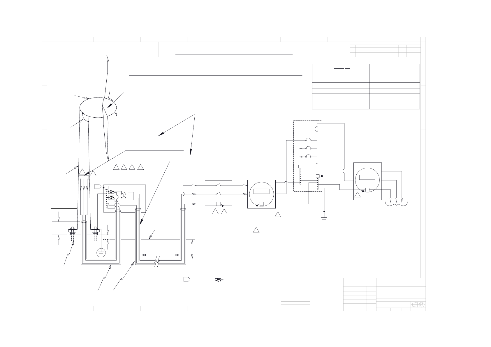
1) TYPICAL GRID CONNECTION:
230 V, 50 Hz, 1 Phase, Junction Box at Tower Base_ ________________________________________________ 3
2 Skystream 3.7® Owner’s Manual, EU Edition, Rev B
Page 33
6
3
2
7
8
40 A
GROUND
SYSTEM
G
CONNECT NEUTRAL AND GND
LUG ONLY IN AC MAIN PANEL
AND NOT IN SUB-PANEL.
2
4
GND
20 A
N
G
N
L1
92 FT.
14 AWG (2.5mm^2)
12 AWG (4mm^2)
146 FT.
USABLE AWG FOR 2% LINE-
NEUTRAL VOLTAGE DROP BETW'N
TURBINE AND MAIN SERVICE
PANEL
SPAN BETW'N
TOWER TOP
TO AC MAIN
PANEL (FOR CU WIRE), ASSUMING
230VAC (L-N) AT THE AC MAIN SERVICE
PANEL, TURBINE OUTPUT 1.8kW
232 FT.
10 AWG (6mm^2)
8 AWG (10mm^2)
371 FT.
5
6" MIN.
VARIATIONS MAY BE MADE IN ACCORDANCE WITH
LOCAL EUROPEAN ELECTRICAL WIRING GUIDELINES
G
12 INCH MAX.
10 INCH MIN.
TOWER
(APPROX.
35 FT.
HIGH)
NACELLE
NACELLE
CHASSIS
ELECTRICALLY
CONNECTED
TO YAW, WHICH
MUST BE
ELECTRICALLY
CONNECTED TO
THE TOWER
GROUND
LEVEL
24 INCH MIN.
RUN FROM JNC. BOX AT
TOWER BASE TO HOME
SAFETY SWITCH
2-POLE, 30A, 240VAC,
SQUARE D #DU221RB
AT TOWER BASE
TOWER
FOUNDATION TOP
SURFACE TO BE
MIN. 6" ABOVE
GROUND LVL.
REFER TO SWWP
FOUNDATION DWG.
"SKYSTREAM"
WIND TURBINE
N
L1
L1 (brown)
#10-2 UFB DIRECT BURIAL
CABLE W/#10 GND FROM YAW
CONNECTION TO SAFETY
SWITCH (230V 1-PH, 50HZ)
L1
TOWER
GROUND
SYSTEM
THIS DRAWING IS FOR REFERENCE
GND (yellow
+green)
N (blue)
DEDICATED
WIND
POWER SYSTEM
KILOWATT-HOUR
METER
#10-2 W/#10 GND THWN-2
CABLE FROM SAFTY SWITCH
TO MAIN SERVICE PANEL
LENGTH < 187 FT.
230V, 1-ph,
AC MAIN
SERVICE
PANEL
N
G
1" DIA. SCHED. 40
RIGID PVC CONDUIT;
SUNLIGHT RESISTANT;
UL LISTED
other loads
WIND POWER
SYSTEM
DISCONNECT
SWITCH 2-POLE
30A, 240VAC
SQ-D #DU221RB
L1
G
4
L1
N
G
UTILITY
KILOWATT-HOUR
METER
230 VAC (L-N)
TO SERVICE
TRANSFORMER,
UTILITY GRID
NOTES:
1. EQUIPMENT SHALL BE INSTALLED IN ACCORDANCE WITH LOCAL EUROPEAN
ELECTRICAL WIRING REGULATIONS.
2. PROVIDE WARNING SIGN READING "WARNING-ELECTRIC SHOCK HAZARD-DO NOT
TOUCH TERMINALS - TERMINALS ON BOTH THE LINE AND LOAD MAY BE
ENERGIZED IN THE OFF POSITION".
3. LABEL "WIND POWER SYSTEM DEDICATED kW-HR METER".
4. LABEL SWITCH AS "WIND GENERATOR SAFETY DISCONNECT SWITCH;
REMOVING AC POWER TO TURBINE ACTIVATES ITS SAFETY BRAKE".
5. OPTION IS TO USE A JUNCTION BOX AT TOWER BASE INSTEAD OF A SWITCH.
6. LABEL "REMOVING AC POWER TO TURBINE ACTIVATES ITS SAFETY BRAKE".
7. BI-DIRECTIONAL METER TO BE INSTALLED BY UTILITY (WHEN REQUIRED).
8. USE COPPER WIRES ONLY AT TURBINE TERMINALS
9.
ALUMINUM WIRES MAY BE USED FOR HOME / UTILITY CONNECTION IF TRANSITION
WERE DONE IN A JNC. BOX. 14AWG WIRE MUST BE COPPER ONLY.
*
N
GND
G
9
CABLE EXAMPLE INDICATES
#10 AWG CABLE BASED ON
45 FT FROM TOWER TO
SWITCH, 187FT FROM SWITCH
TO MAIN PANEL. TOTAL 232
FT. FOR LONGER SPANS
SEE WIRE CHART.
588 FT.
934 FT.
6 AWG (16mm^2)
4 AWG (25mm^2)
SPD
NOTE 10.
SPD = SURGE PROTECTIVE DEVICE SUCH AS A
LIGHTNING CURRENT ARRESTOR. AN APPROPRIATE
ARRESTOR TO SATISFY THE REQUIRED LIGHTNING
PROTECTION LEVEL MUST BE INSTALLED. SEE
LIGHTNING PROTECTION SECTION OF MANUAL FOR
RECOMMENDATIONS
B
B
Proprietary rights are included in the information disclosed herein. This information is
submitted in confidence and neither the document nor the information disclosed herein shall be reproduced or transferred to other documents for manufacturing or for any
other purpose except as specifically authorized in writing by Southwest Windpower.
D
E
F
C
1
2
3
4
B
A
3
2
1
5
C
D
4
6
7
8
A
B
-
-
3-CMLT-1085 rev B+ 230V 50HZ 1PH
N.Agrawal
3-CMLT-1085
Skystream
8 Mar
'07
Flagstaff, Arizona U.S.A.
CAD-generated drawing
do not manually update
scale none
size A3
CAD file :
doc. n°
sheet 1 of 1
rev. B
DATE
APPROVALS
DRAWN
CHECKED
RESP ENG
MFG ENG
QUAL ENG
DO NOT SCALE DRAWING
APPLICATION
USED ON
NEXT ASSY
E
-
REVISIONS
REV.
DESCRIPTION
DATE
APPROVED
-
230 V 50Hz 1Ph
W/ JCT BOX
5
-
-
4/13/07
ECO# 1180
NC
-
A
ECO 1212
5/24/07
Admin Ch# 0056
B
12/08/08
tg
Southwest Windpower
Fig. 1. Typical Grid Connection: 230 V, 1 Phase, Junction Box at Tower
Skystream 3.7® Owner’s Manual, EU Edition, Rev B 3
Page 34

Page 35
APPENDIX B: TOWER
GROUNDING
Skystream Energy Europe GmbH
A wholly-owned subsidiary of Southwest Windpower, Inc.
Mannesmannstr. 6
50996 Cologne
Germany
Tel: +49 (0) 221 16 53 94 50
[email protected]
www.skystreamenergy.eu
No vembe r 2010 Sky st ream Energy Eur op e
All Rights Reserved
Page 36
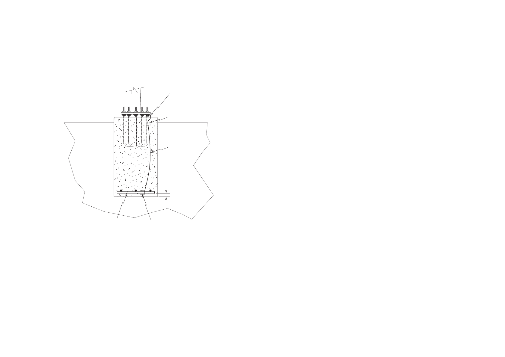
Skystream 3.7® Owner’s Manual
20 ft (6 m) of 0.5 in
(1.3 cm) dia.
re-bar OR 4AWG
(25 mm2)
or larger
bare c
opper conductor
2 inch (5 cm) min.
at foundation
bottom
Listed or approved clamp for
connecting Copper to steel.
Clamp is generally tin plated and
must prevent direct contact between
Cu and steel to prevent corrosion
4AWG (25 mm2)
or larger
copper
wire
Internal bonding
to tower bolts using
listed or approved clamp
External bond to tower
SOIL
CONCRETE
3
2
1
5
C
D
4
6
7
8
A
B
Flagstaff, Arizona U.S.A.
CAD-generated drawing
do not manually update
DA T E
APPROVALS
Unless otherwise specified
dimensions are in mm.
tolerances are :
distances angles
X. ± .5 ± 30 '
E
POT
01/29/06
Original
release
NC
REVISIONS
REV.
DESCRIPTION
DA T E
APPROVED
Concrete encased
Appendix B: Tower Grounding
Important Safety Instructions ______________________________ 3
1) INTRODUCTION _____________________________________ 4
2) GROUNDING TECHNIQUES __________________________ 4
2-1 Copper Clad Electrodes Driven Into Soil _______________ 4
2-1-1 Grounding Electrode Installation _______________ 5
2-1-2 Electric Resistance to Ground _________________ 5
2-1-3 Grounding Electrode Conductor: Material, Size,
Bonding to Electrode & Bonding to Tower ____________ 6
2-1-4 Conductor Size _____________________________ 6
2-1-5 Bonding the Grounding Electrode Conductor to
the Earth Electrode _______________________________ 6
2-1-6 Bondng the Grounding Electrode Conductor to the
Tower ___________________________________________ 6
2-1-6-1 Using a Tower Bolt/Nut Assembly ___________ 6
2-1-6-2 Using a Grounding Lut at Tower Base ________ 7
2-1-6-3 Using Exothermic Welding __________________ 7
2-2 Electrodes Encased in the Concrete of the Tower Foundation
2-3 Bolting Grounding Lug to Tower Base ________________ 8
2 Skystream 3.7® Owner’s Manual, EU Edition, Rev B
Page 37
IMPORTANT SAFETY INSTRUCTIONS
READ THESE IN STRUCTIONS IN THEIR ENTIRETY BEFORE INSTALLING.
Professional installation
highly recommended
1) SAVE THESE INSTRUCTIONS. This manual contains important instructions
for grounding your Skystream tower.
2) Read these instructions in their entirety before beginning.
3) Do not start installation unless all required equipment and tools are on site.
In this guide
TIP: Helpful information
to ease the installation
Professional installation
highly recommended
Warning: Risk of injury or
death - proceed with extreme
caution
Skystream 3.7® Owner’s Manual, EU Edition, Rev B 3
Page 38
8 ft
(2.4 m)
1 ft
(0.3 m)
(16 mm2) Min Must be
secured and buried for
protection
One - Introduction
Even though the wind turbine is grounded at the service panel it must also be
grounded at the tower base. Grounding the tower at its base may prevent electrical shocks, voltage surges and static charge build up. Proper tower grounding
may also limit or minimize damage due to lightning strikes.
This document provides recommendations for grounding small wind turbine
systems with rated line currents of less than 200A to achieve compliance with
the 2005 USA National Electrical Code (NEC) as well as IEC (International
Electrotechnical Commission) standard 60364-5-54 Selection and Erection
of Electrical Equipment – Earthing Arrangements, Protective Conductors and
Protective Bonding Conductors.
The grounding information contained in this document is provided as a
reference. Please refer to the aforementioned NEC and IEC standards
for complete detailed information. Local building codes and electrical
standards may differ from the information presented here and have
precedence over this document.
Two - Grounding Techniques
There are several tower grounding techniques compliant with NEC and IEC
standards, this document presents two of the most common approaches:
• Copper clad electrodes driven into the soil
• Electrodes encased in the concrete of the tower foundation
2-1 Copper Clad Electrodes Driven Into the Soil
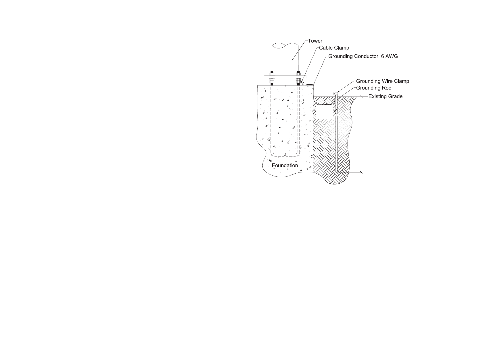
The figure 1 depicts a typical tower grounded using an electrode driven into
the soil.
The tower may be grounded using a copper-clad electrode(s) of appro
priate diameter and length. See the section entitled “Electrode resi-
4 Skystream 3.7® Owner’s Manual, EU Edition, Rev B
Fig. 1 Electrode driven into ground.
tance to ground” to determine the dimensions of the rod. The electrode
shall be free from non-conductive coatings such as paint or enamel. Rod
and pipe electrodes shall not be less than 2.5 m in length and shall
consist of the following materials:
a) Electrodes of pipe or conduit (hollow electrodes) shall not be smaller than
metric designator 21 (trade size 3/4) and, where of iron or steel, shall have
the outer surface galvanized or otherwise metal-coated for corrosion protection.
b) Electrodes of rods of iron or steel shall be at least 15.87 mm in diameter.
Stainless steel rods less than 16 mm in diameter, nonferrous rods, or their
equivalent shall be listed* and shall not be less than 13 mm in diameter.
Page 39

NEC section 250.52 and in accordance with the user’s local electrical code
authority.
*Be included in a list published by an organization (or marked as
such) that is acceptable to the local authority having jurisdiction in
the area. For example, UL/CSA listed in USA/Canada.
2-1-1 Grounding Electrode Installation
The following information is excerpted from the 2005 NEC article 250.53 (G).
Refer to code for additional detailed information.
The electrode shall be installed such that at least 2.44 m of length is in contact with the soil. It shall be driven into undisturbed soil within 1 ft of the tower
foundation. It shall be driven to a depth of not less than 2.44 m except that,
where rock bottom is encountered, the electrode shall be driven at an oblique
angle not to exceed 45 degrees from the vertical or, where rock bottom is
encountered at an angle up to 45 degrees, the electrode shall be permitted to
be buried in a trench that is at least 750 mm deep. The upper end of the electrode shall be flush with or below ground level unless the aboveground end and
grounding electrode conductor are protected against physical damage as specified below (quoted from 2005 NEC article 250.10):
a) In installations where they are not likely to be damaged.
For calculating the resistance of the rod to ground, one must know the value of
soil resistivity. This may be found in the local electrical code or building inspector’s office/municipal office or by an actual soil resistivity test.
The resistance of a rod electrode to ground may be lowered by increasing the
rod diameter, increasing the buried length of the rod or by treatment of the soil
to reduce its resistivity.
If the single chosen electrode does not have a resistance to ground of 10 ohm
or less, it shall be augmented by additional electrodes as necessary. The overall
resistance of multiple rods to ground would roughly equal the resistance of a
single rod to ground divided by the number of rods. Where multiple such electrodes are installed to meet the above requirement, they shall not be less than
1.8 m apart. The multiple rods must be bonded together using the grounding
electrode conductor.
b) Where enclosed in metal, wood, or equivalent protective covering.
2-1-2 Electrode Resistance to Ground
The resistance to earth of a single ground rod can be calculated using Dwight’s
equation:
R = [r/(2πL)]x[ln(4L/R)-1], where r is the soil resistivity, L is the length of the rod
buried inside the earth and R = radius of the rod; ln stands for the natural logarithm.
Skystream 3.7® Owner’s Manual, EU Edition, Rev B 5
Page 40

2-1-3 Grounding Electrode Conductor:
Material, Size, Bonding to Electrode and Bonding to Tower
Material (Ref. 2005 NEC articles 250.62, 250.96(A).
The grounding electrode conductor shall be of copper, aluminum, or copper-clad
aluminum. The material selected shall be resistant to any corrosive condition
existing at the installation or shall be suitably protected against corrosion. The
conductor shall be solid or stranded, insulated, covered or bare. Any non-conductive paint, enamel, or similar coating shall be removed at threads, contact
points, and contact surfaces or be connected by means of fittings designed so
as to make such removal unnecessary.
Note: Many local electrical standards do not permit the use of aluminum or copper-clad aluminum conductor and strictly require the use of copper conductors.
2-1-4 Conductor Size
(Ref. 2005 NEC article 250.66(A)):
Where the grounding electrode conductor is connected to rod, pipe or plate
electrodes, that portion of the conductor that is the sole connection to the
grounding electrode shall be a minimum of 6AWG copper wire or 4AWG aluminum wire.
2-1-5 Bonding the Grounding Electrode Conductor to the Earth Electrode
(Ref. 2005 NEC article 250.70):
The grounding or bonding conductor shall be connected to the grounding
electrode by exothermic welding, listed lugs, listed pressure connectors, listed
clamps, or other listed means. Connections depending on solder shall not be
used. Ground clamps shall be listed (approved) for the materials of the grounding electrode and the grounding electrode conductor and, where used on pipe,
rod or other buried electrodes, shall also be listed for direct soil burial.
2-1-6 Bonding the Grounding Electrode Conductor to the Tower
The grounding conductor may be connected to the tower by any one the following means:
2-1-6-1 Using a Tower Bolt/Nut Assembly
a) Pre-assemble the extra nut (supplied in the tower bolt kit) on one of the
tower bolts containing nuts “A” or “B” as shown in fig. 2C of Skystream
Foundation and Tower Installation Manual. Move the extra nut towards the
bottom of the bolt so that it does not interfere with the nut to go on top of it.
b) Assemble the nut and washer on top as explained in the Installation Manual.
Generously apply a listed “joint compound” to the sandwiching surfaces of
the two nuts as well as to the tower bolt in question. The joint compound
must be of the type to prevent corrosion between copper and galvanized
steel.
c) Take one end of the grounding conductor and loop it once around the tower
bolt containing the extra nut, between the upper and lower nut. Generously
apply joint compound to the grounding conductor and cable clamp in the
area of attachment. Secure the conductor with a cable clamp around the
loop so that it just clears the tower nuts and keeps the loop snug around the
tower bolt (see fig. 3). The cable clamp is required so that the ground wire
does not slip out from between the nuts when the lower nut is tightened.
d) Ensure that surfaces of the lower and upper nuts facing each other are free
of dirt and have very clean surfaces. If necessary, wash and clean these surfaces. This is essential for a good electrical connection between the ground
conductor and the tower. Tighten the lower nut towards the upper nut applying sufficient torque (68 N-m minimum) to securely clamp the grounding
wire (see Fig. 3).
e) Erect the tower and level it as required by adjusted any or all of the tower
nuts. You may have to loosen the ground wire nut during this adjustment.
After finished adjusting the tower level, re-tighten the lower nut to the suggested torque to make sure the ground wire is securely sandwiched and
bound between the two nuts.
6 Skystream 3.7® Owner’s Manual, EU Edition, Rev B
Page 41
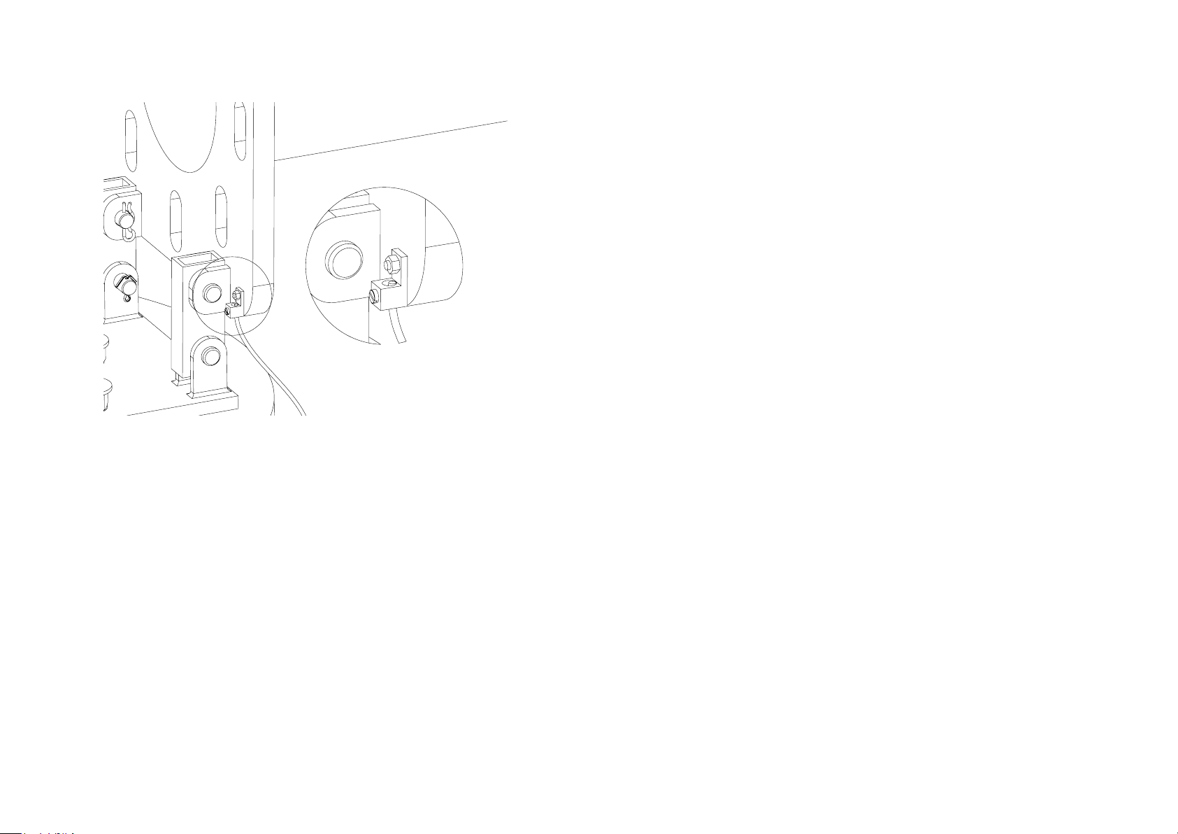
A
DETAIL A
SCALE 1 : 1
Fig. 2 Attaching the grounding wire to the tower base.
2-1-6-2 Using a Grounding Lug at Tower Base
Bond the grounding conductor to the tower base flange through a ground terminal lug attached to the tower base as shown in figure 2. Use a 1/4-20 x 1.75
in long stainless steel bolt through a hole in the tower base and a Nyloc stainless steel nut to fasten the ground lug to the underside of the tower base. The
ground lug must be UL listed and must be type to that accommodates up to 1/
0 AWG wire minimum.
2-1-6-3 Using Exothermic Welding
Bond the grounding conductor to the tower base flange by exother welding of
the conductor to the base flange. Make exothermic welds strictly in accordance
with the weld manufacturer’s written recommendations.
Electrode conductor routing and placement / installation:
Ensure that the grounding conductor has no sharp bends in it. This is important
to keep its inductance low. The grounding conductor may be buried or contained
in a conduit as explained in 2005 NEC article 250.64.
2-2 Electrodes encased in the concrete of the tower foundation
(reference 2005 NEC article 250.52(A)(3))
A grounding electrode may also be encased in the concrete of the tower foundation. The electrode is located at the bottom of the foundation and connects
to the tower mounting “J” bolts and to the tower base by means of a grounding
conductor.
Because the grounding electrode will be encased in concrete it should be
inspected and approved prior to pouring the foundation to avoid conflicts with
local construction inspectors.
Two types of electrodes, their locations and their connection to the electrode
grounding conductor are described below:
a) The Electrode must be at least 6.0 m of one or more (electrically connected
by steel tie wires) bare or zinc galvanized steel or other electrically conductive coated steel reinforcing bars or rods of not less than 13 mm in diameter,
located near the bottom of the concrete foundation that is in direct contact
with the earth. The electrode must be encased by at least 50 mm of concrete as shown in figure 4. The reinforcing bars, if bare, must not be rusted
at the time of installation to prevent bad electrical connection between bars
and with the grounding electrode conductor. The reinforcing bars must be
electrically connected to the anchor bolts either using the steel tie wires or
using the grounding electrode conductor. The grounding electrode conductor must not be smaller than 4AWG copper and must be electrically bonded
to the bottom reinforcing bars using listed/approved means that is suitable
for concrete encasement. Sufficient extra length of the conductor must be
available to bring it out of the foundation top and at least 46cm above the
foundation top. It should then be bonded to the tower as described in section 2-1-6 of this document.
Skystream 3.7® Owner’s Manual, EU Edition, Rev B 7
Page 42
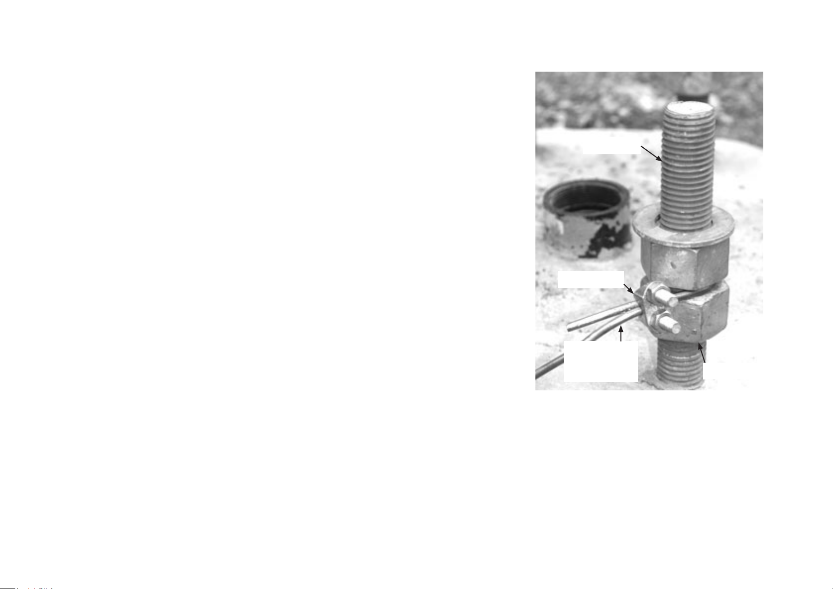
b) The Electrode must be least 20 ft (6.0 m) of bare copper conductor not smaller than 4AWG.
The copper conductor, which may be in the form of a coil, must lie at the bottom of the foundation with either a 2-in thick (maximum) tamped fill of earth covering the grounding coil
or covered in concrete a maximum of 2 in above the soil at the bottom of the foundation.
Sufficient extra length must be present in the copper conductor to bring it at least 18 inch
above the foundation top where it should be bonded to the tower as described in section
1.5 of this document. On its way up, the copper conductor must also be bonded to the tower
anchor bolts using a clamp listed or approved means that is suitable for concrete encasement
and also suitable for connecting copper to steel. This listed clamp is generally tin plated and
must be of the type to prevent direct contact between copper and steel to prevent corrosion.
2-3 Bolting Grounding Lug to Tower Base
An alternate method of attaching the electrode grounding conductor to the tower is to drill a hole
thorough the base and utilize a commercially available lug as depicted in figure 2. To connect the
grounding conductor to the tower base using this approach drill a 0.25 in (6 mm) hole through the
tower base. After joining the grounding conductor to the listed lug according to the lug manufacturer’s instructions, bolt the lug to the tower base with a stainless steel bolt and self locking nut.
The listed lug is generally tin plated and prevents corrosion between the galvanized steel tower
and the copper conductor.
Tower Bolt
Cable Clamp
Ground
Electrode
Conductor
Lower Nut
8 Skystream 3.7® Owner’s Manual, EU Edition, Rev B
Fig. 3 Tower foundation bolt.
Page 43
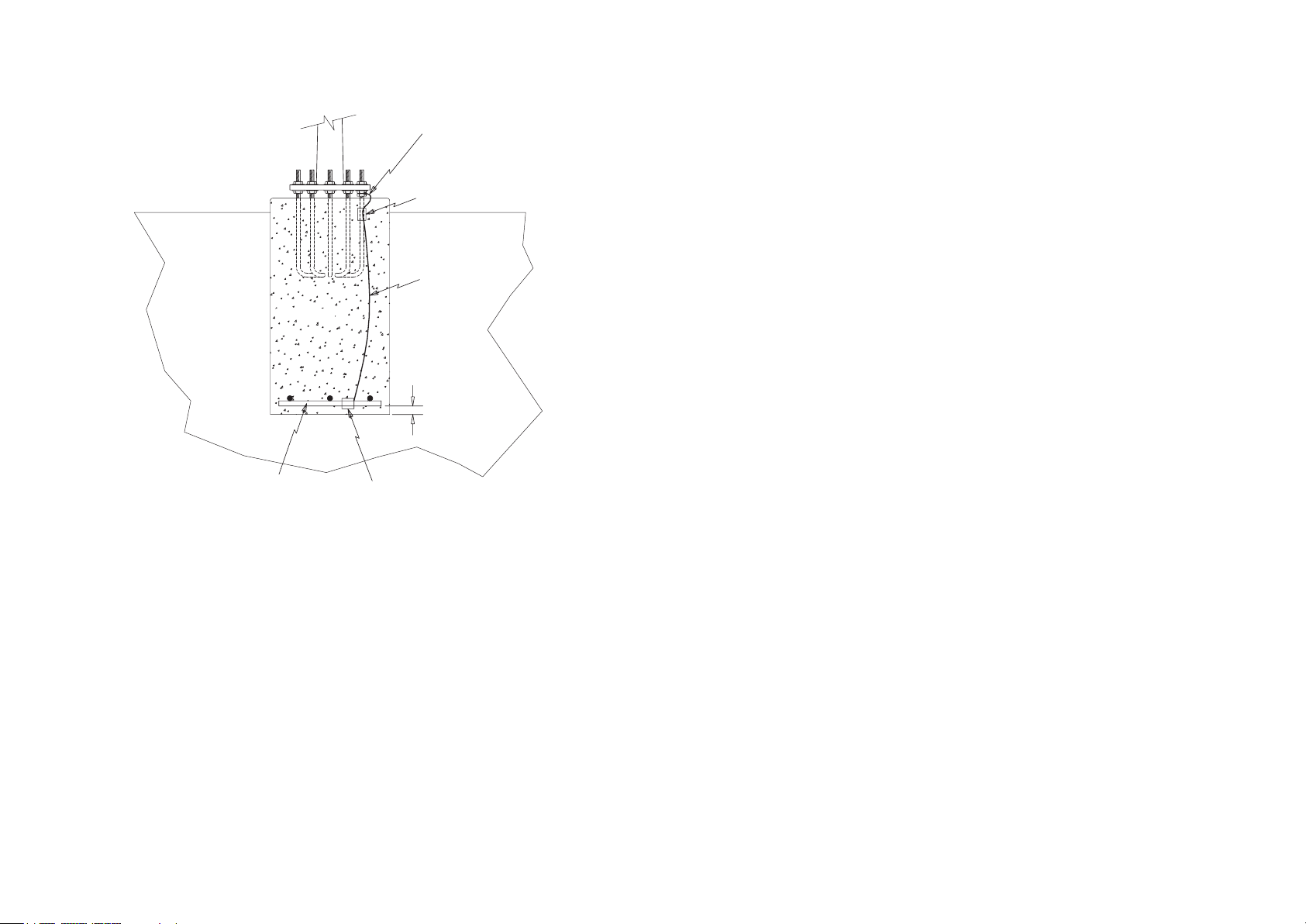
20 ft (6 m) of 0.5 in
(1.3 cm) dia.
re-bar OR 4AWG
(25 mm2)
or larger
bare c
opper conductor
2 inch (5 cm) min.
at foundation
bottom
Listed or approved clamp for
connecting Copper to steel.
Clamp is generally tin plated and
must prevent direct contact between
Cu and steel to prevent corrosion
4AWG (25 mm2)
or larger
copper
wire
Internal bonding
to tower bolts using
listed or approved clamp
External bond to tower
SOIL
CONCRETE
3
2
1
5
C
D
4
6
7
8
A
B
Flagstaff, Arizona U.S.A.
CAD-generated drawing
do not manually update
DA T E
APPROVALS
Unless otherwise specified
dimensions are in mm.
tolerances are :
distances angles
E
POT
01/29/06
Original
release
NC
REVISIONS
REV.
DESCRIPTION
DA T E
APPROVED
Concrete encased
Fig. 4 Concrete encased electrode.
Skystream 3.7® Owner’s Manual, EU Edition, Rev B 9
Page 44

Page 45
APPENDIX C:
LIGHTNING PROTECTION
Skystream Energy Europe GmbH
A wholly-owned subsidiary of Southwest Windpower, Inc.
Mannesmannstr. 6
50996 Cologne
Germany
Tel: +49 (0) 221 16 53 94 50
[email protected]
www.skystreamenergy.eu
No vembe r 2010 Sky st ream Energy Eur op e
All Rights Reserved
Page 46

Skystream 3.7® Owner’s Manual
Appendix C: Lightning Protection
Important Safety Instructions ______________________________ 3
Introduction ____________________________________________ 4
Location of Lightning Current Arrestors______________________ 4
Selecting Appropriate Lightning Protection System ____________ 4
Determine Tower Height __________________________________ 5
Determine Flash Density __________________________________ 5
Table 1: Lightning Protection Efficiency for 33 ft Tower ________ 5
Determine Topography ____________________________________ 6
Permitted Annual Number of Critical Event (Nc) _______________ 6
Lightning Protection System Efficiency ______________________ 6
Table 2: Lightning Protection Efficiency for 45 ft Tower ________ 6
Table 3: Lightning Protection Efficiency for 60 ft Tower ________ 7
Table 4: Lightning Protection Efficiency for 70 ft Tower ________ 8
Lightning Protection Level ________________________________ 8
Select Model & Number of Lightning Current Arrestor(s) _______ 9
2 Skystream 3.7® Owner’s Manual, EU Edition, Rev B
Page 47
IMPORTANT SAFETY INSTRUCTIONS
READ THESE IN STRUCTIONS IN THEIR ENTIRETY BEFORE INSTALLING.
Professional installation
highly recommended
1) SAVE THESE INSTRUCTIONS. This manual contains important instructions
for grounding your Skystream tower.
2) Read these instructions in their entirety before beginning.
3) Do not start installation unless all required equipment and tools are on site.
In this guide
IMPORTANT:
Please take note
Professional installation
highly recommended
Warning: Risk of injury or
death - proceed with extreme
caution
Skystream 3.7® Owner’s Manual, EU Edition, Rev B 3
Page 48
Introduction
The Skystream 3.7 turbine is designed to withstand over voltages and surge
currents (6kV, 3kA, 8/20µs) caused by indirect lightning strikes or switching
operations according to the Standard for Interconnecting Distributed Resources
with Electric Power Systems (IEEE 1547). For this protection to be effective, it
is necessary to ensure that over voltages at the connection terminals will not be
higher than the above values of the surge test.
To provide this over voltage protection against direct lightning strikes; a Type 1
lightning current arrestor, that reduces over voltages to a level below 6 kV but
is capable of discharging very high currents, much larger than those handled by
surge protective devices present inside Skystream is required. Type 1 lightning
arrestors have been tested to withstand over voltages and surge currents representing a direct lightning strike, described by a 10/350µs type waveform.
Selecting the Appropriate Lightning Protection System
An appropriate Lightning Protection System is selected after determining the
Lightning Protection System Efficiency and thus the Lightning Protection Level
(Level 1 through 4). To determine these, one needs to further determine the following parameters.
The parameters include:
• The tower height
• Flash Density (Ng)
• Topography of Installation site
• Permitted Annual Number of Critical Events (Nc)
Once these parameters are defined a specific Model of Lightning Current Arrestor may be determined.
Since the Skystream is intended to be installed worldwide in all kinds of environments, some more vulnerable to lightning than others, the Lightning Protection System’s (LPS) efficiency (E), and hence the current rating of the Type 1
Lightning Current Arrestor, may be selected to meet local requirements.
Location of the Lightning Current Arrestor(s):
For Skystream installations with metallic tubular towers where the tower and
turbine installation, earthing or grounding has been performed as per the
Owner’s manual, analysis has shown that the best protection is provided when
the Type 1 arrestor is placed at or near the base of the tower.
4 Skystream 3.7® Owner’s Manual, EU Edition, Rev B
IMPORTANT: More than one arrestor may be required
depending upon the level of protection required.
The Lightning Protection System (LPS) “Protection Level” is based on the number
of lightning “critical events” allowed per year and the lightning flash density in the
target area. A “critical event” is described as the failure of the lightning protection
system (LPS).
If there is risk of damage to the wind turbine or associated power networks and
devices due to a critical event (or injury or loss of life), then the protection system must be designed to keep the Permitted Annual Number of Critical Events,
Nc, under an acceptable value. This is the acceptable number of annual lightning
strikes that will cause one damage incident.
IMPORTANT: Nc is generally set by the local jurisdiction or by the
owner or installer of the system and needs to meet local safety laws.
Page 49
Determine Tower Height
Table 1 - Lightning Protection Efficiency for 33 ft (10m) Towers
Determine your tower height and select Table 1, 2, 3 or 4 corresponding to
a 33, 45, 60 or 70 ft. tower (10, 14, 18 or 21 m). Tables 1, 2, 3 and 4 are
utilized to calculate the Lightning Protection System Efficiencies corresponding to the tower height.
IMPORTANT: If the tower height falls in between the heights for which the tables
are available in this manual, select the table for the next higher tower height.
Determine the Flash Density (Ng)
Determine the Annual Average Ground Flash Density (per km2), Ng, in your
area. This number may be obtained from information published by National
organizations, meteorological organizations and is generally available on the
internet. For example, Global Atmospherics Inc. (also known as Vaisala-GAI
Inc.), publishes lightning strike data. Be careful to obtain most recent data
available, as there may be considerable variability in data from one year to
next, especially with the present climate change.
An example website is given below:
http://www.crh.noaa.gov/pub/?n=/ltg/flash_density_maps_index.php
Ng may range anywhere between 1 and 70. Select the row corresponding to
the Ng in your area. For non-integer values, the next higher integral number
must be chosen.
Warning: Be careful to obtain most recent data available, as
there may be considerable variability in data from one year to
next, especially with the present climate change.
Isolated Flat Land Hill or Knoll Non-Isolated Flat Land
Ng E = Lightning protection
system efficiency
Nc =
1/100
0.01 0.001 0.0001 0.01 0.001 0.0001 0.01 0.001 0.0001
-1.353 0.765 0.976 -0.176 0.882 0.988 -3.705 0.529 0.953
1
-0.176 0.882 0.988 0.412 0.941 0.994 -1.353 0.765 0.976
2
0.216 0.922 0.992 0.608 0.961 0.966 -0.568 0.843 0.984
3
0.412 0.941 0.994 0.706 0.971 0.997 -0.176 0.882 0.988
4
0.529 0.953 0.995 0.765 0.976 0.998 0.059 0.906 0.991
5
0.608 0.961 0.996 0.804 0.980 0.998 0.216 0.922 0.992
6
0.664 0.966 0.997 0.832 0.983 0.998 0.328 0.933 0.993
7
0.706 0.971 0.997 0.853 0.985 0.999 0.412 0.941 0.994
8
0.739 0.974 0.997 0.869 0.987 0.999 0.477 0.948 0.995
9
0.765 0.976 0.998 0.882 0.988 0.999 0.529 0.953 0.995
10
0.786 0.979 0.998 0.893 0.989 0.999 0.572 0.957 0.996
11
0.804 0.980 0.998 0.902 0.990 0.999 0.608 0.961 0.996
12
0.819 0.982 0.998 0.910 0.991 0.999 0.638 0.964 0.216
13
0.832 0.983 0.998 0.916 0.992 0.999 0.664 0.966 0.997
14
0.843 0.984 0.998 0.922 0.992 0.999 0.686 0.969 0.997
15
0.853 0.985 0.999 0.926 0.993 0.999 0.706 0.971 0.997
16
0.862 0.986 0.999 0.931 0.993 0.999 0.723 0.972 0.997
17
0.869 0.987 0.999 0.935 0.993 0.999 0.739 0.974 0.997
18
0.876 0.988 0.999 0.938 0.994 0.999 0.752 0.975 0.998
19
0.882 0.988 0.999 0.941 0.994 0.999 0.765 0.976 0.998
20
0.922 0.992 0.999 0.961 0.996 1.000 0.843 0.984 0.998
30
0.941 0.994 0.999 0.971 0.997 1.000 0.882 0.988 0.999
40
0.953 0.995 1.000 0.976 0.998 1.000 0.906 0.991 0.999
50
0.961 0.996 1.000 0.980 0.998 1.000 0.922 0.992 0.999
60
0.966 0.967 1.000 0.983 0.998 1.000 0.933 0.993 0.999
70
Nc =
1/1000
Nc =
1/10000
E = Lightning protection
system efficiency
Nc =
1/100
Nc =
1/1000
1/10000
Nc =
E = Lightning protection
system efficiency
Nc =
1/100
Nc =
1/1000
Nc =
1/10000
Skystream 3.7® Owner’s Manual, EU Edition, Rev B 5
Page 50
Determine the Topography
Table 2 - Lightning Protection Efficiency for 45 ft (14m) Towers
Inspect the topography of the area in which the turbine is installed and select
the one category that best describes the topography:
• Isolated Flat Land: No structures present within a circle of radius three
htimes the height of the turbine (with the turbine at the centre of the circle)
• Knoll / Hill
• Un-isolated Flat Land: Smaller structures present within a circle of radius
three times the height of turbine (with turbine at centre of the circle)
Permitted Annual Number of Critical Events (Nc)
Determine Nc. Three “Annual Number of Critical Event” options are provided
in the tables. The least protective option is 1 /100 (1 in 100); the most protective is 1/10000 (1 in 10,000).
Warning: If there is risk of injury or danger to human life,
then maximum allowed Nc is generally 1 in 100,000 or
less, depending on laws of various states or countries.
As Skystream installations on relatively short towers (like 33 ft - 70 ft / 10m
- 21m) do not significantly increase risk of injury or danger to human life, the
Efficiency (E) is calculated with higher values of Nc (for example, 1/1000 is
larger than 1/100,000).
However, Nc must be chosen to comply with local electrical safety laws. Some
authorities may require Nc = 1/100,000 for better protection. The result of
choosing such a low Nc would mean that a lightning protection system with
Level 1 protection will need to be installed.
Isolated Flat Land Hill or Knoll Non-Isolated Flat Land
Ng
-0.427 0.875 0.986 0.287 0.929 0.993 -1.853 0.715 0.971
1
2
3
4
5
6
7
8
9
10
11
12
13
14
15
16
17
18
19
20
30
40
50
60
70
efficiency efficiency efficiency
Nc =
1/100
0.01 0.001 0.0001 0.01 0.001 0.0001 0.01 0.001 0.0001
0.287 0.929 0.993 0.643 0.964 0.996 -0.427 0.857 0.986
0.524 0.952 0.995 0.762 0.976 0.998 0.049 0.905 0.990
0.643 0.964 0.996 0.822 0.982 0.998 0.287 0.929 0.993
0.715 0.971 0.997 0.857 0.986 0.999 0.429 0.943 0.994
0.762 0.976 0.998 0.881 0.988 0.999 0.524 0.952 0.995
0.796 0.980 0.998 0.898 0.990 0.999 0.592 0.959 0.996
0.822 0.982 0.998 0.911 0.991 0.999 0.643 0.964 0.996
0.841 0.984 0.998 0.921 0.992 0.999 0.683 0.968 0.997
0.857 0.986 0.999 0.929 0.993 0.999 0.715 0.971 0.997
0.870 0.987 0.999 0.935 0.994 0.999 0.741 0.974 0.997
0.881 0.988 0.999 0.941 0.994 0.999 0.762 0.976 0.998
0.890 0.989 0.999 0.945 0.995 0.999 0.781 0.978 0.998
0.898 0.990 0.999 0.949 0.995 0.999 0.796 0.980 0.998
0.905 0.990 0.999 0.952 0.995 1.000 0.810 0.981 0.998
0.911 0.991 0.999 0.955 0.996 1.000 0.822 0.982 0.998
0.916 0.992 0.999 0.958 0.996 1.000 0.832 0.983 0.998
0.921 0.992 0.999 0.960 0.996 1.000 0.841 0.984 0.998
0.925 0.992 0.999 0.962 0.996 1.000 0.752 0.985 0.998
0.929 0.993 0.999 0.964 0.996 1.000 0.857 0.986 0.999
0.952 0.995 1.000 0.976 0.998 1.000 0.905 0.990 0.999
0.964 0.996 1.000 0.982 0.998 1.000 0.929 0.993 0.999
0.971 0.997 1.000 0.986 0.999 1.000 0.943 0.994 0.999
0.976 0.998 1.000 0.988 0.999 1.000 0.952 0.995 1.000
0.980 0.998 1.000 0.990 0.999 1.000 0.959 0.996 1.000
Nc =
1/1000
Nc =
1/10000
Nc =
1/100
Nc =
1/1000
Nc =
1/10000
Nc =
1/100
1/1000
Nc =
Nc =
1/10000
6 Skystream 3.7® Owner’s Manual, EU Edition, Rev B
Page 51
Table 3 - Lightning Protection Efficiency for 60 ft (18m) Towers
The Lightning Protection System Efficiency (E)
Isolated Flat Land Hill or Knoll Non-Isolated Flat Land
Ng
1/100
0.143 0.914 0.991 0.572 0.957 0.996 -0.714 0.829 0.983
1
2
0.714 0.971 0.997 0.857 0.986 0.999 0.429 0.943 0.994
3
0.786 0.979 0.998 0.893 0.989 0.999 0.572 0.957 0.996
4
0.829 0.983 0.998 0.914 0.991 0.999 0.657 0.966 0.997
5
0.857 0.986 0.999 0.929 0.993 0.999 0.714 0.971 0.997
6
7
0.893 0.989 0.999 0.946 0.995 0.999 0.786 0.979 0.998
8
0.905 0.990 0.999 0.952 0.995 1.000 0.810 0.981 0.998
9
0.914 0.991 0.999 0.957 0.996 1.000 0.829 0.983 0.998
10
0.922 0.992 0.999 0.961 0.996 1.000 0.844 0.984 0.998
11
0.929 0.993 0.999 0.964 0.996 1.000 0.857 0.986 0.999
12
0.934 0.993 0.999 0.967 0.997 1.000 0.868 0.987 0.999
13
0.939 0.994 0.999 0.969 0.997 1.000 0.878 0.988 0.999
14
0.943 0.994 0.999 0.971 0.997 1.000 0.886 0.989 0.999
15
0.946 0.995 0.999 0.973 0.997 1.000 0.893 0.989 0.999
16
0.950 0.995 0.999 0.975 0.997 1.000 0.899 0.990 0.999
17
0.952 0.995 1.000 0.976 0.998 1.000 0.905 0.990 0.999
18
0.955 0.995 1.000 0.977 0.998 1.000 0.910 0.991 0.999
19
0.957 0.996 1.000 0.979 0.998 1.000 0.914 0.991 0.999
20
30
40
0.983 0.998 1.000 0.991 0.999 1.000 0.966 0.997 1.000
50
0.986 0.999 1.000 0.993 0.999 1.000 0.971 0.997 1.000
60
0.988 0.999 1.000 0.994 0.999 1.000 0.976 0.998 1.000
70
efficiency efficiency efficiency
Nc =
0.01 0.001 0.0001 0.01 0.001 0.0001 0.01 0.001 0.0001
0.572 0.957 0.996 0.786 0.979 0.998 0.143 0.914 0.991
0.878 0.988 0.999 0.939 0.994 0.999 0.755 0.976 0.998
0.971 0.997 1.000 0.986 0.999 1.000 0.943 0.994 0.999
0.979 0.998 1.000 0.989 0.999 1.000 0.957 0.996 1.000
Nc =
1/1000
Nc =
1/10000
Nc =
1/100
Nc =
1/1000
Nc =
1/10000
Nc =
1/100
1/1000
Nc =
Nc =
1/10000
Using the appropriate Efficiency Table for the tower height, select the subcolumn corresponding to the installation topography – Isolated Flat Land, Hill
or Knoll, or Non-isolated Flat Land.
The data cell at the intersection of Flash Density value (Ng) row and the
Permitted Number of Critical Events (Nc) column will indicate The Lightning
System Efficiency “E”. If E is negative, no lightning protection is required.
IMPORTANT: If “E” is negative, no lightning protection is required.
Skystream 3.7® Owner’s Manual, EU Edition, Rev B 7
Page 52
Table 4 - Lightning Protection Efficiency for 70 ft (21m) Towers
Isolated Flat Land Hill or Knoll Non-Isolated Flat Land
Ng
1/100
1
2
3
4
5
6
7
8
9
10
11
12
13
14
15
16
17
18
19
20
30
40
50
60
70
efficiency efficiency efficiency
Nc =
0.01 0.001 0.0001 0.01 0.001 0.0001 0.01 0.001 0.0001
0.352 0.935 0.994 0.676 0.968 0.997 -0.296 0.870 0.987
0.676 0.968 0.997 0.838 0.984 0.998 0.352 0.935 0.994
0.784 0.978 0.998 0.892 0.989 0.999 0.568 0.957 0.996
0.838 0.984 0.998 0.919 0.992 0.999 0.676 0.968 0.997
0.870 0.987 0.999 0.935 0.994 0.999 0.741 0.974 0.997
0.892 0.989 0.999 0.946 0.995 0.999 0.784 0.978 0.998
0.907 0.991 0.999 0.954 0.995 1.000 0.815 0.981 0.998
0.919 0.992 0.999 0.960 0.996 1.000 0.838 0.984 0.998
0.928 0.993 0.999 0.964 0.996 1.000 0.856 0.986 0.999
0.935 0.994 0.999 0.968 0.997 1.000 0.870 0.987 0.999
0.941 0.994 0.999 0.971 0.997 1.000 0.882 0.988 0.999
0.946 0.995 0.999 0.973 0.997 1.000 0.892 0.989 0.999
0.950 0.995 1.000 0.975 0.998 1.000 0.900 0.990 0.999
0.954 0.995 1.000 0.977 0.998 1.000 0.907 0.991 0.999
0.957 0.996 1.000 0.978 0.998 1.000 0.914 0.991 0.999
0.960 0.996 1.000 0.980 0.998 1.000 0.919 0.992 0.999
0.962 0.996 1.000 0.981 0.998 1.000 0.924 0.992 0.999
0.964 0.996 1.000 0.982 0.998 1.000 0.928 0.993 0.999
0.966 0.997 1.000 0.983 0.998 1.000 0.932 0.993 0.999
0.968 0.997 1.000 0.984 0.998 1.000 0.935 0.994 0.999
0.978 0.998 1.000 0.989 0.999 1.000 0.957 0.996 1.000
0.984 0.998 1.000 0.992 0.999 1.000 0.968 0.997 1.000
0.987 0.999 1.000 0.994 0.999 1.000 0.974 0.997 1.000
0.989 0.999 1.000 0.995 0.999 1.000 0.978 0.998 1.000
0.991 0.999 1.000 0.995 1.000 1.000 0.981 0.998 1.000
Nc =
1/1000
Nc =
1/10000
Nc =
1/100
Nc =
1/1000
Nc =
1/10000
Nc =
1/100
1/1000
Nc =
Nc =
1/10000
The Lightning Protection Level
Refer to Table 5, the “Lightning Protection Level” and using the Efficiency
(E) determine the Lightning Protection Level (LPL) and corresponding
peak lightning current discharge capability.
Lightning Protection Level 1 provides highest level of protection and Lightning Protection Level 4, the lowest level of protection.
Table 5 - Lightning Protection Level
Efficiency Lightning Protection Level
E > 0.980 Lightning Protection Level 1
with additional measures
0.95 < E < = 0.98 Lightning Protection Level 1
0.90 < E < = 0.95 Lightning Protection Level 2
0.80 < E < = 0.90 Lightning Protection Level 3
0 < E < = 0.80 Lightning Protection Level 4
8 Skystream 3.7® Owner’s Manual, EU Edition, Rev B
Page 53
Select Model and Number of Lightning Current Arrestor(s)
Select the appropriate model and quantity of the Type 1 lightning current
arrestor(s) required from Table 6. The selection method is described below:
The lightning arrestor peak current rating is the peak current carrying capability of each pole or contact of the arrestor. It is generally assumed that the total
current the surge arrestor will end up carrying (cumulatively, in all its phases), is
about 50% of the total lightning discharge current. Say, if there is 100kA of peak
discharge current due to lightning, 50kA will flow through ground, and the other
50kA will be divided between L1, L2 and N, thus requiring the surge arrestor to
be rated for ~16kA per phase.
This concept of lightning current division is described in Reference (3) listed at
Lightning and surge protection is intended to be placed between each phase
(hot line) conductor and ground, and possibly between ground and neutral, if the
distance between the neutral and ground bond is significant. Therefore the voltage rating of the SPD is to be based on phase (hot line) to neutral values (since
neutral and ground are connected at the main service panel, and hence normally
at the same potential).
Following table shows example lightning current arrestor recommendations
(single pole versions with spark-gap technology).
Note: Lightning Current Arrestors from DEHN Inc. have been cited here, however, comparable arrestors from other companies may be utilized.
the end of the lightning protection description.
Table 6 - Type 1 Lightning Current Arrestor Recommendations: One Pole Versions (spark-gap technology)
Efficiency Lightning
Protection Level
(LPL)
E > 0.980 LPL with added
measures
0.95 < E < = 0.98 LPL 1 200kA DB M 1 150, one each
0.90 < E < = 0.95 LPL 2 150kA DB M 1 150, one each between
0.80 < E < = 0.90 LPL 3 100kA DB M 1 150, one each
0 < E < = 0.80 LPL 4 100kA DB M 1 150, one each
Notes: Above specified arrestors are manufactured by DEHN Inc. Part number & price for above models are:
DEHNblock Maxi 150 (DB M 1 150), part#, 961 110, limp = 35kA, list price $268.00 as of May 2008
DEHNblock Maxi 255 (DB M 1 255), part#, 961 120, limp = 50kA, list price $336.00 as of May 2008
The arrestors shown above are manufactured by DEHN Inc. and may be obtained in the USA by ordering from:
DEHN Inc., 106 SW Peacock Blvd. # 207
Port St. Lucie, FL 34986
Tel: (772) 340-7006; Fax: (772) 343-0703
Peak Lightning
Current Discharge/
Sinking Capability
200kA DEHNbloc Maxi 150 (DB M 1 150),
120/240V split 1-ph and
120/208V system
(L1, L2, N, G)
AT LEAST one each L1-G, L2-G, N-G
between L1-G, L2-G, N-G
L1-G, L2-G (N-G optional)
between L1-G, L2-G
between L1-G, L2-G
References:
1) IEC 61400-24, IEC 61400-2.
2) DEHN Lightning Protection Guide
3) Characteristics of Direct Strike Lightning Events and Risk Assessment,
Dr. –Ing Peter Hasse, Managing Director, DEHN, PEG 2001 Meeting,
Las Vegas, March 27-29, 2001.
4) National Electric Code, 2005 Handbook, National Fire Protection
Association (USA).
230V, 1-ph system
(L, N, G)
DB M 1 255, AT LEAST one
each between L-G, N-G
DB M 1 255, one each
between L-G, N-G
DB M 1 255, one each
between L-G, N-G
DB M 1 255, one between
L-G (N-G optional)
DB M 1 255, one between
L-G (N-G optional)
Skystream 3.7® Owner’s Manual, EU Edition, Rev B 9
Page 54

Page 55
APPENDIX D:
CERTIFICATION/COMPLIANCE
Skystream Energy Europe GmbH
A wholly-owned subsidiary of Southwest Windpower, Inc.
Mannesmannstr. 6
50996 Cologne
Germany
Tel: +49 (0) 221 16 53 94 50
[email protected]
www.skystreamenergy.eu
No vembe r 2010 Sky st ream Energy Eur op e
All Rights Reserved
Page 56

Certificate Number
20090219E300731
Page 1 of 2
Report Reference
E300731, Issued: 2006-10-17
Issue Date
2009 February 19
Issued to:
Southwest Windpower Inc
1801 W Rte 66
Flagstaff, AZ 86001
United States
This is to certify that
representative samples of
Component inverter for use with Skystream wind turbine, Utility Interactive Ready
Have been investigated by Underwriters Laboratories in accordance with
Standard(s) for Safety:
UL 1741, Standard for Safety for Inverters, Converters, Controllers and
Interconnection System Equipment for Use With Distributed Energy Resources, 1st
Ed.; IEEE 1547-2003; CAN/CSA-C22.2 No.107.1-01, 3rd Ed.
Additional Information:
See Addendum
Look for the UL Recognized Component Mark on the product
Issued by:
Chris Storbeck
Reviewed by:
Tim Zgonena
Chris Storbeck, Sr. Project Engineer Tim Zgonena, Primary Designated Engineer
Underwriters Laboratories Inc. Underwriters Laborator ies Inc.
Any information and documentation involving UL Mark services are provided on behalf of Underwriters Laboratories Inc. (UL) or any auth orized licensee of UL.
For questions in The United States of America you may call 1-877-UL- HELPS.
Only those products bearing the UL Recognized Component Marks for the U.S. and Canada should be considered as being covered by UL's
Recognition and Follow-Up Service and meeting the appropriate U.S. and Canadian requirements.
The UL Recognized Component Mark for the U.S. generally consists of the manufacturer’s identification and catalog number, model number or other product
designation as specified under “Marking” for the particular Recognition as published in the appropriate UL Directory. As a supplementary means of identifying
products that have been produced under UL’s Component Recognition Program, UL’s Recognized Component Mark:
, may be used in conjunction with the
required Recognized Marks. The Recognized Component Mark is required when specified in the UL Directory preceding the recognitions or under “Markings” for
the individual recognitions. The UL Recognized Component Mark for Canada consists of the UL Recognized Mark for Canada:
and the manufacturer’s
identification and catalog number, model number or other product designation as specified under “Marking” for the particular Recognition as published in the
appropriate UL Directory.
1. UL Certificate of Compliance (US & Canada) page 1
2 Skystream 3.7® Owner’s Manual, EU Edition, Rev B
Page 57

2. UL Certificate of Compliance (US & Canada) page 2
Certificate Number
20090219E300731
Page 2 of 2
Report Reference
E300731, Issued: 2006-10-17
Issue Date
2009 February 19
Addendum - Skystream Inverter
Inverter Output configuration: 120/240V, L-N-L,
Operating voltage range Vac: 212-264; or
Output Configuration: 120/208V, L-N-L,
Operating voltage range Vac: 183-229;
Normal output frequency Hz: 60.0;
Operating frequency range Hz: 59.3-60.5;
Rated output current Aac: 10.0;
Rated continuous output power kW@25 °C: 2.3;
Rated continuous output power kW@50°C: 1.5;
Max. peak output kW: 2.4;
Surge Category B
Alternate Firmware Combinations approved since Jan. 28, 2008:
Inverter Master Application Code: Inverter Slave Application Code:
Revision: Rev 1.11.10 Revision: Rev 1.03
Revision: Rev 2.00.0 Revision: Rev 1.03
Revision: Rev 2.02.0 Revision: Rev 1.03
Representative samples of the SkyStream Inverter as specified on this certificate were evaluated and
tested according to all current UL 1741 requirements. All Testing was performed on representative
samples of the Wind Turbine system including tests to certify the Nacelle as a suitable enclosure. Unit
has been tested and meets all requirements for Utility Interactive operation in accordance with:
- UL 1741, Standard for Safety for Inverters, Converters, Controllers and Interconnection System
Equipment for Use With Distributed Energy Resources, 1st Ed., Revised: November 7, 2005
- IEEE 1547-2003 Standard for Interconnecting Distributed Resources with Electric Power Systems;
-IEEE 1547.1-2005 Standard Conformance Test Procedures for Equipment Interconnecting Distributed
Resources with Electric Power Systems, dated: June 2003
- CAN/CSA-C22.2 No.107.1-01, 3rd Ed., General Use Power Supplies, dated: September 2001
Issued by:
Chris Storbeck
Reviewed by:
Tim Zgonena
Chris Storbeck, Sr. Project Engineer Tim Zgonena, Primary Designated Engineer
Underwriters Laboratories Inc. Underwriters Laboratori es Inc.
Any information and documentation involving UL Mark services are provided on behalf of Underwriters Laboratories Inc. (UL) or any auth orized licensee of UL.
For questions in The United States of America you may call 1-877-UL- HELPS.
Skystream 3.7® Owner’s Manual, EU Edition, Rev B 3
Page 58
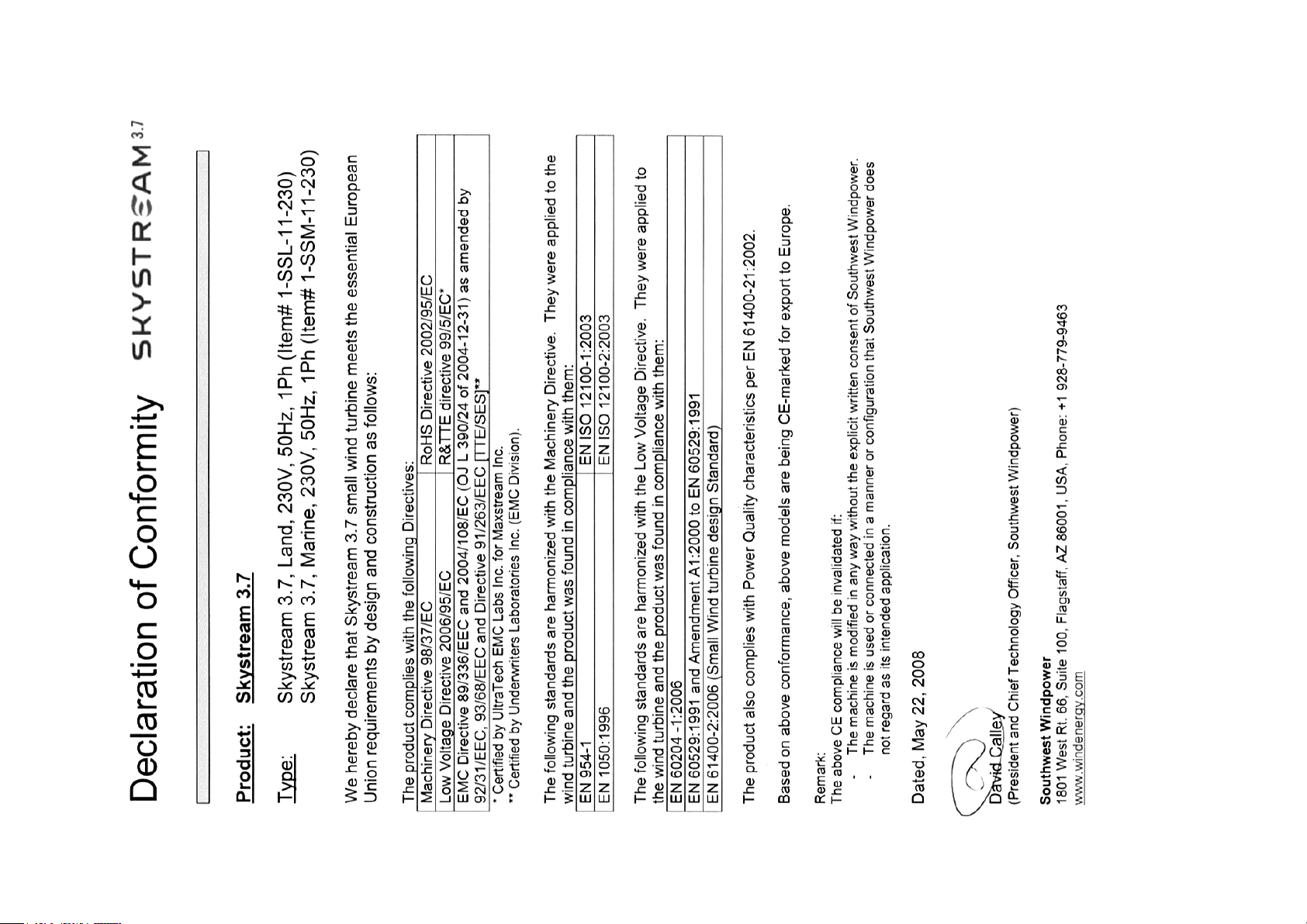
3. CE Declaration of Conformity (Europe)
4 Skystream 3.7® Owner’s Manual, EU Edition, Rev B
Page 59

Page 60

Page 61

Page 62

Page 63

Page 64

Skystream Energy Europe GmbH
A wholly-owned subsidiary of Southwest Windpower, Inc.
Mannesmannstr. 6
50996 Cologne
Germany
Tel: +49 (0) 221 16 53 94 50
[email protected]
www.skystreamenergy.eu
 Loading...