

Southwest Specialty Products 6800 User Manual
6800 ROM MONITOR
VERSON 1.0
USERS GUIDE
Southwest Technical Products Corporation
219 W. Rhapsody San Antonio, Texas 78116
Copyright 1977, Southwest Technical Products Corporation
Scanned and edited by Michael Holley Sept. 17, 2000 Revised Aug. 6, 2002
Southwest Technical Products Corporation Document Circa 1977

SWTPC SWTBUG® (SWATBUG) MONITOR ROM
One of the features of the SWTPC 6800 Computer System is that the conventional
programmer’s console has been replaced with a monitor ROM. The programmer’s console
consists of all the pretty switches and lights often found on similar microcomputers that are used
to bootstrap the system after power up. The programmer’s console not only raises the cost of the
system, but more often than not is confusing and tedious to use for both be-ginning and
experienced programmers. The monitor ROM on the other hand is a permanently stored program
that gives the computer the intelligence required to communicate with the operator thru an
interfaced terminal system immediately after power up without flipping switches for 10 minutes.
This technique makes the computer do the work of simplifying communication between itself and
the operator.
SWTBUG® is the name of the monitor program used in the SWTPC 6800 Computer
System. It might be thought of as kind of a mini-operating system since it gives the operator
command control over the computer system.
Features of the SWTBUG® ROM include:
∗ Memory Examine and Change
∗ Program loading from cassette or paper tape thru the control interface or thru I/O port # 0.
∗ Program saving to cassette or paper tape
∗ Go to user program
∗ Display contents of registers
∗ Erase SWTPC CT-1024 terminal system screen
∗ SWTPC MF-68 floppy disk boot
∗ Byte search
∗ Breakpoint debugging
∗ Vectored hardware and software interrupts to user defined addresses
SWTBUG® is a permanently stored program and cannot be erased or lost by either a loss of
power or user program error. It is always resident in the computer while power is ON and need
never be loaded into the machine. Subroutines within the ROM are documented and available to
the user to simplify programming and conserve on the use of user RAM memory. Character input
and output, string output and return to monitor are just a few subroutines available to the user.
SWTBUG® is a 1K byte program and is addressed high in memory, far above the amount of
RAM memory required for most user programs. Since SWTBUG® does require a small amount of
RAM memory for operation, a 128 byte scratchpad RAM has been implemented on the processor
board so that no external user RAM memory is required for monitor operation. There is even
enough extra room in this RAM so that short programs such as memory diagnostics can be
loaded into and run from the scratchpad RAM without requiring any external user RAM memory.
Extra care however must be exercised to avoid overstoring any memory locations required for
proper monitor operation. Complete de-tails on this are given later in this writeup. The
SWTBUG® ROM is located from memory addresses E000 thru E3FF. The scratchpad RAM is
located from memory addresses A000 thru A07F. Both components are physically located on the
processor board and are functional any time the system is powered up. Whenever computer
control is transferred from SWTBUG® to the user program, there are only four ways to get back
into the SWTBUG® command mode. The first is to put a jump to the CONTRL entry point
address within SWTBUG® as the last step of your program. The second is to incorporate a
command or action within your program which transfers program control to the CONTRL entry
point address within SWTBUG® The third is to depress the front panel RESET button. The fourth
is turn the computer OFF and then back ON again. The fourth method is rather drastic and wipes
out all RAM memory data, it is only mentioned to let you know that the computer always powers
up with the SWTBUG® monitor in the command mode.
1
SWTBUG® INSTALLATION
SWTBUG® is a MOS device and MOS integrated circuits are susceptible to damage by
static electricity. Although some degree of protection is provided internally within the integrated
circuits, their cost demands the utmost in care. Before opening and/or installing SWTBUG® you
should ground your body and all metallic tools coming into contact with the leads, thru a 1M ohm
¼ watt resistor. The ground must be an “earth” ground such as a water pipe, and not the circuit
board ground. As for connection to your body, attach a clip lead to your watch or metal ID
bracelet. Make absolutely sure that you have the resistor connected between you and the “earth”
ground, otherwise you will be creating a dangerous shock hazard. Avoid touching the leads of the
integrated circuits any more than necessary when installing it, even if you are grounded. Static
electricity should be an important consideration in cold, dry environments. It is less of a problem
when it is warm and humid.
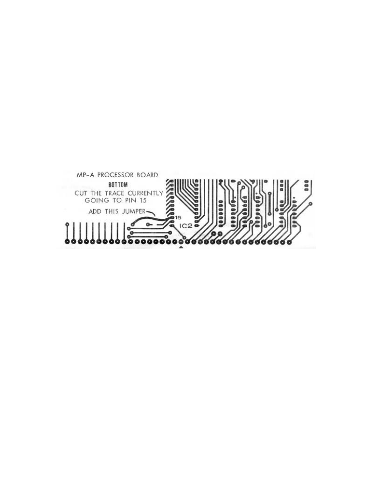
When using SWTBUG® with an MP-A processor card, one board change is necessary since
SWTBUG® is a full 1 K ROM and MIKBUG® was a 1/2K device, If this ROM is replacing
MlKBUG, remove MIKBUG® from its socket. On the back side of the MP-A board you will notice
that pin 15 of IC-2 (ROM) is grounded. The land coming from pin 15 should be broken and a wire
added as shown below.
SWTBUG® should now be installed in the socket for IC-2. Be sure to orient the ROM
correctly when re-installing. The semicircle notch or dot should match with the MP-A board’s
component layout drawing. When installing SWTBUG® in the MP-A2 processor board no board
modifications are necessary. Follow the instructions supplied with the MP-A2 instruction set.
SWTBUG® OPERATION
The SWTBUG® firmware enables the computer to communicate with a terminal to perform
various programming and debugging functions. SWTBUG® will communicate with a terminal via
either a MP-C control interface or MP-S ACIA serial interface on I/O port 1. An optional MP-C
interface can be installed on I/O port 0 for punch and load functions. Although SWTBUG® is
essentially compatible with MIKBUG, be sure to read the COMPATIBILITY section before running
any programs written for MIKBUG. Below is a detailed description of each SWTBUG® command.
RESET
Upon receiving a RESET command, as during power up, SWTBUG® will initialize the
system to receive commands from a terminal. When the RESET button is pushed, control will
transfer to location E0D0 of SWTBUG®. The RESET button should be used for exiting loops or
malfunctioning programs. After resetting, the computer should respond with a carriage return, line
feed and a $ sign. At this point, SWTBUG® is waiting for commands. If breakpoints are being
used, the RESET function will not disable breakpoints. The BREAKPOINT function should be
referenced for additional information.
2

MEMORY EXAMINE AND CHANGE M (addr)
The Memory Examine and Change function can be used to enter machine code programs
and to display and/or change the contents of memory. The Memory Examine and Change
function should be used as follows:
1.) Type M. The computer should echo the M and output a space.
2.) Type in the four digit hexadecimal address that you wish to examine and/or change.
The computer should respond with a carriage return, line feed, $, the address and the
data that is stored at this address.
3.) At this point the user has the option of advancing, either forward or backward, to the
next memory location, or changing the data stored at the displayed address and
advancing to the next location or of exiting the M function.
a.) To display the next sequential address and data, a line feed or any character other
than 0123456789ABCDEF:;^=>? or a space or a carriage return may be entered.
Any leading spaces that are entered will be ignored by the memory change
function.
b.) To display the next sequential address going backward from the present location, a
^ should be entered.
c.) To change the data stored at the displayed location, enter the new data, either with
or without a leading space. If a non-hex value, such as a 3Q is entered the data will
remain unchanged and the memory change function will be exited. If the data is
unable to be changed (write protected memory, etc.) a ? will be output and the
memory change function will be exited.
d.) To exit the Memory Examine and Change function, type a carriage return.
Below is an example. The underlined parts are what was entered by the user.
$M 0100 MEMORY LOCATION 0100 OPENED
$0100 00 . DISPLAY NEXT LOCATION
$0101 BD . DISPLAY NEXT LOCATION – SPACE IGNORED
$0102 5D . DISPLAY NEXT LOCATION
$0103 C1 01 CHANGE CONTENTS TO 01
$0104 C9 23 CHANGE CONTENTS TO 23. SPACES IGNORED
$0105 15 ^ READ PREVIOUS LOCATION
$0104 23 . DISPLAY NEXT LOCATION
$0105 15 3Q ENTER NON-HEX VALUE
$M 0105 SWTBUG CONTROL RESUMED. OPEN NEW LOCATION
$0105 15 EXIT BY HITTING CARRIAGE RETURN
$M E000 OPEN ANOTHER LOCATION
$E000 FE 56? ATTEMPTED TO CHANGE A WRITE PROTECTED MEMORY
$ SWTBUG CONTROL RESUMED
REGISTER DUMP FUNCTION R
The R command will display the current contents of the MPU's pushdown stack. “Current”
means the status of data stored on the stack immediately before SWTBUG® control is resumed.
The following is a typical register dump:
$R
$FF 16 23 17EC 0103 A042
$
CONDITION
CODES
ACC B ACC A INDEX
REG
PGM.
CTR.
STACK
PTR
3

The condition codes are as defined below:
BIT NO. LABEL CONDITION CODE
0 C Carry-borrow
1 V Overflow
2 Z Zero
3 N Negative
4 I Interrupt mask
5 H Half carry
In the above example the condition code of "3C" can be interpreted as follows:
3C16 =
0 0 1 1 1 1 0 0
BIT 7 BIT 6 BIT 5 BIT 4 BIT 3 BIT 2 BIT 1 BIT 0
Below are two examples of how the R command works. Assume that this small program was
entered to change certain registers.
$M 0100
$0100 CE 8E LOADS STACK POINTER TO 100
$0101 12 10
$0102 34 00
$0103 86 CE LOAD INDEX REGISTER WITH 1234
$0104 00 12
$0105 C6 34
$0106 FF 86 LOAD ACCUMULATOR A WITH 00
$0107 FD 00
$0108 08 C6 LOAD ACCUMULATOR B WITH FF
$0109 23 FF
$010A 67 7E JUMP BACK TO SWTBUG CONTROL
$010B F7 E0
$010C 60 E3
$010D DD
AT THIS POINT THE STATUS WILL NOT BE PUSHED ON THE STACK
4

$R
$FF DC FC 6EFD 0100 A042 REGISTER DUMP BEFORE RUNNING PROGRAM
$G
$R
$FF DC FC 6EFD 0100 A042 NOTE R DUMP THE SAME AFTER RUNNING
$J 0100
$R
$FF DC FC 6EFD 0100 A042 THE SAME AFTER A JUMP
$M 010A AT THIS POINT THE JUMP TO SWTBUG CONTROL
$010A 7E 3F IS REPLACED BY A SWI. NOTE THE VALUE
$010B 50 OF THE REGISTERS AFTER THE NEXT DUMP.
$G
$F9 FF 00 1234 010A 0FF9 REGISTER DUMP GIVEN BY SWI
$R
$F9 FF 00 1234 010A 0FF9 DUMP SHOWS PROGRAM CHANGES
$
$FF DC FC 6EFD 0100 A042 R DUMP AFTER RESET
In the above program you will notice that the register dump after running the program is the
same as before even though the program contained statements that changed the processor’s
registers. The register dump did not reflect these changes because the new conditions were not
pushed on the computer’s stack. Note, however, the register dump did reflect the change when
the last instruction was a software interrupt -- a SWI instruction will push the processor’s status
on the stack and then display the contents of the registers.
CT-1024 CLEAR SCREEN COMMAND C
The C command outputs a home-up (1016) and an erase to end of frame (1616) control
characters for the clearing of the screen on a SWTPC CT-1024 or equivalent terminal system.
GO TO USER’S PROGRAM FUNCTION G
Upon entering a G command, SWTBUG® will transfer control to the user’s program by
executing a RTI (return from interrupt) instruction. This effectively causes the computer to jump to
the memory address stored in memory locations A048 and A049 in the SWTBUG® RAM. A048
contains the most significant byte and A049 the least significant byte of the memory address. If,
for example, you wish to execute a program starting at 0100, change A048 to a 01 using the M
function and change A049 to 00. Typing a G will then cause the computer to execute the program
whose starting address is 0100. Upon entering a program using the G function, the stack pointer
will be set at A049. The G function is also used to restart a program after a breakpoint has been
moved. In this case A048 and A049 should not be changed. See the Breakpoint section for
further information.
JUMP TO USER’S PROGRAM J(addr)
The J command will cause the computer to execute the program whose starting address is
given in the entered address. The J command does not look at locations A048 and A049. The
stack pointer will be set at A042 upon entering a program with a jump command. Example: J
0100. If a non-hex character is entered, SWTBUG® control will resume.
ASCII TAPE PUNCH COMMAND P
The P command provides a means for storing the contents of specified memory on either
cassette or paper tape. Normal output from the computer during a punch is thru either an MP-C
or MP-S serial interface on I/O port 1, but a MP-C interface on I/O 0 can be selected. (See the
description of the O command.) To use the P command, the upper and lower limits of the range
to be punched must first be stored in locations A002-A005 of the SWTBUG® RAM. If you wanted
to punch from addresses 0123 to 4567 (inclusive) you would use the memory examine and
change functions to set computer memory as follows.
5
 Loading...