


Southwest Microwave, Inc.
Security Systems Division
MicroTrack
A BURIED TERRAIN FOLLOWING
OUTDOOR PERIMETER INTRUSION DETECTION SYSTEM
User Guide
Preliminary Edition
Version 1.0

1. Introduction 5
1.1 MicroTrack Security Applications
1.2 MicroTrack Sensor Characteristics
1.3 MicroTrack Features and Benefits
1.4 Comparison to Past Generation Buried Cable Sensors
1.5 MicroTrack System Components
1.5.1 Major Hardware and Software Components
MicroTrack Processor (MTP)
MicroTrack Sensor Cable Assembly (MTC400)
MicroTrack Site Manager Software (MTS)
1.5.2 Installation and Spare Components
MicroTrack Enclosure - Non-Metallic (MTE-NM)
MicroTrack Enclosure - Metallic (MTE-ME)
MicroTrack Enclosure - Stainless Steel (MTE-SS)
MicroTrack Enclosure - Pedestal (MTE-PE)
MicroTrack Link (MTL)
MicroTrack Termination (MTT)
MicroTrack Splice Kit (MTS)
MicroTrack Lead-in Cable Assembly (02A15909-A01)
MicroTrack Sensor Cable (MTC400)
1.5.3 Optional Hardware and Software Components
Relay Module (RM)
Map Monitor Software with PC and Color Monitor
1.6 MicroTrack System Configuration Parameters
2.
MicroTrack System Components 13
(section to be completed when production hardware is available)
3.
Site Planning and System Configuration 14
3.1 Site Survey
3.2 System Configuration and Layout
3.2.1 Determining Total Sensor Cable Length
3.2.2 Lead-in Cable and Connectors
3.2.3 Determining the Quantity of Sensor Cable Assemblies per System
3.2.4 Determining the Quantity of MicroTrack Processor (MTP) Units
3.2.4.1 Network and Standalone Configurations
3.2.4.2 Redundant Power and Data System Configuration
3.2.4.3 Positioning and Powering MTP Units
3.2.5 Determining the Quantity of Systems per Map Monitor
3.2.6 Adding Auxiliary Sensor Inputs and Outputs to MTP’s
3.2.7 When to use a Relay Module (RM)
3.2.8 Sensor Cable Installation Components
3.2.8.1 Determining the Quantity of MicroTrack Links (MTL)
3.2.8.2 Determining the Quantity of MicroTrack Terminations (MTT)
3.2.8.3 Determining the Quantity of Splice Kit (MTS)
3.3 Sample System Configuration – A Four MTP Redundant Closed-loop System
3.4 Sample System Configuration – A Two MTP Open Loop System with Auxiliary
Sensors
MicroTrack User Guide 2 April 1, 2004

4.
System Design 23
4.1
System Design Parameters
4.1.1
4.1.2
4.1.3
4.1.4
4.1.5
4.1.6
4.1.7
4.1.8
4.1.9
4.1.10
4.1.11
4.1.12
4.1.13
4.1.14
4.1.15
4.1.16
4.1.17
4.1.18
MicroTrack Installation 43
5.
Selecting the Optimum Sensor Cable Spacing and Position Near Fences
Proximity to Fences and Fence Types
Burial Medium Conductivity
Site Environment and Occurrence of Frost
Double Fences , Concertina and Razor Tape
Animals and the Detection Field
Cable Spacing Near Buildings
Accommodating Grass, Trees and Shrubs
Uneven Terrain
Rain, Standing Water and Run-off
Burying Sensor Cables in Soil
Burying Sensor Cables in Concrete or Asphalt with a Thickness ≥10 cm (4
inches)
Burying MicroTrack Sensor Cables in Concrete or Asphalt with a Thickness
<
10 cm (4 inches)
Burying MicroTrack Sensor Cables in a Variety of Installation Mediums
Bypassing Large Non-metallic Drainage Pipes and Culverts
Buried Electrical Cables, Conduits and Wires
Overhead Electrical Cables and Conduits
Lead-in and Sensor Cable Startup – Linear
Lead-in and Sensor Cable Startup – Corner
Making Turns with Sensor Cables
Terminating the Sensor Cable Near Buildings
5.1 Staking out the Location of MicroTrack Components on the Perimeter
5.2
Installing MicroTrack Processors (MTP)
5.2.1
5.2.2
5.2.3
5.2.4
5.3
Installing Sensor Cables and Components
5.3.1
5.3.2
5.3.3
5.3.4
5.3.5
5.3.6
5.3.7
5.3.8
5.4
Installing MicroTrack Links (MTL)
5.4.1
Positioning the MTP
Installing the MicroTrack Enclosure (MTE) and Protecting Cables
Grounding the MTP
Power and Data Connections between the MTP and the Control Center
5.2.4.1
5.2.4.2
Installing Sensor Cable Assemblies
Personnel and Equipment Required to Install Sensor Cable Sets
General Guidelines for Installing Sensor Cable Assemblies
Cable Trenching
Inspecting and Laying-out MTC400 Sensor Cable Assemblies
Guidelines for Installing the First MTC400 Sensor Cable Assembly
Guidelines for Installation of the Second MTC400 Sensor Cable Assembly
Guidelines for the Installation of an Adjacent MTC400 Sensor Cable Assembly
Guidelines to Install an MTL on a Sensor Cable Assembly
Connecting the Map Monitor using RS422
Connecting the Power Supply to the MTP
MicroTrack User Guide 3 April 1, 2004

5.4.2
5.5
Installing MicroTrack Terminations (MTT)
5.5.1
5.6
Final Connections
5.7
Backfilling the Cable Trenches
APPENDIX 1 – MICROTRACK SPECIFICATIONS (to be inserted in final edition)
APPENDIX 2 – SITE SURVEY CHECKLIST
Copyright Southwest Microwave, Inc. April 2004
Southwest Microwave, Inc.
9055 South McKemy Street
Tempe, Arizona 85284-2956
Tel: (480) 783-0201
Fax: (480) 703-0401
Email:
Web: www.southwestmicrowave.com
infossd@southwestmicrowave.com
Guidelines to Install an MTL on an Adjacent Sensor Cable Assembly
Guidelines to Install an MTT at the End of a Sensor Cable Assembly
MicroTrack User Guide 4 April 1, 2004
MicroTrack
A BURIED TERRAIN FOLLOWING
OUTDOOR PERIMETER INTRUSION DETECTION SYSTEM
User Guide – Preliminary Edition
1. Introduction
Welcome to Southwest Microwave’s new buried cable outdoor perimeter intrusion detection system –
MicroTrack – the most advanced buried cable sensor system available. MicroTrack is the first buried
cable sensor that is truly site-adaptive and can both detect and locate intruders. MicroTrack is a smart
sensor with an integral power and data network. It is patented and it is the first outdoor intrusion
detection sensor to use ultra wide band FS/PCM (frequency stepped, phase code modulated) technology –
the same technology used in radar altimeters.
MicroTrack is the latest member of Southwest Microwave’s Intrepid family of outdoor perimeter
intrusion detection products. And, like its cousin, MicroPoint, it also incorporates Sensitivity Leveling
and Free Format Zoning. MicroTrack is terrain following with the ability to go up and down hills and
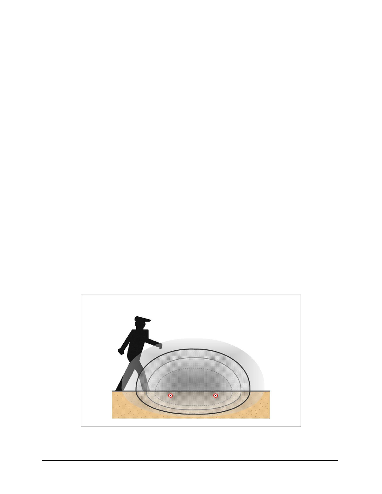
around corners. It provides a large invisible detection field and operates in difficult environmental
conditions with a very high probability of detection and low false and nuisance alarm rate. MicroTrack
uses Multi-Segment Target Analysis (MSTA) – a new concept in sensor design enabling each sensor
cable to be divided into small subcells (each 1.1 meter (3.6 ft.) in length) to be independently adapted to
site conditions and analyzed. MicroTrack overcomes numerous limitations of past generation buried
cable sensors.
This User Guide provides instructions on site planning and how to install and operate MicroTrack.
Figure 1.1 MicroTrack Terrain Following Detection Field
MicroTrack User Guide 5 April 1, 2004

1.1 MicroTrack Security Applications
MicroTrack can be used to detect intruders entering and/or leaving a secure facility. It is typically
installed on the secure side of the facility and in close proximity to a fence (or wall). In high security
applications involving two fences (or walls), MicroTrack is commonly installed between the fences.
MicroTrack can also be installed in open areas provided there is some means, such as a low profile
courtesy fence (or wall) to limit access to the system, to avoid nuisance alarms from large animals and
passers-by. Typical site applications are listed and illustrated below.
• Military installations
• Parked aircraft areas
• Government facilities
• Nuclear power plants
• Electrical substations
• Equipment storage areas
• Pharmaceutical plants
• Correctional facilities
• Commercial airports
• VIP estates
• Oil, gas and petrochemical facilities
• R&D facilities
• Banking and computer centers
• Vehicle parking areas
• Communications facilities
• Border crossing area
1.2 MicroTrack Sensor Characteristics
The MicroTrack sensor consists of an electronics processor unit and two pairs of buried sensor cables. A
detection field is created around each pair of sensor cables for a distance of up to 200 meters, or a total of
400 meters per processor. The cables are buried in soil, asphalt, concrete or other burial medium. The
processor uses ultra wide band FS/PCM transmission to create an invisible electromagnetic detection field
around and along the cables. This approach provides a far superior probability of detection (Pd) and
lower false and nuisance alarm rate (FAR/NAR) compared to other sensors. MicroTrack can also
communicate with and provide power to a variety of auxiliary sensors.
MicroTrack detects walking, running, crawling, rolling and jumping intruders. MicroTrack will locate
intruders to within approximately five meters (16 ft.). It will also operate in unfavorable and changing
environmental conditions, including, rain, wind, snow, hail, fog, blowing sand and seismic effects. The
processor unit transmits radio frequencies between 20 and 30 MHz through one of the sensor cables
which acts as a transmit cable. The second sensor cable acts as a receive cable and provides information
back to the processor. This process creates an electromagnetic surface wave moving above the ground
surface and along the cables. An intruder crossing the cables significantly changes the surface wave, thus
altering the return signal on the receive cable. The processor unit compares the transmitted and received
signals in terms of phase and amplitude and declares an alarm when changes occur which match a human
intruder. MicroTrack will also detect tunnelers moving within one meter (3 ft.) of the sensor cable.
Detailed performance specifications for MicroTrack are provided in Appendix 1.
MicroTrack User Guide 6 April 1, 2004

1.3 MicroTrack Features and Benefits
MicroTrack provides a combination of features and performance benefits unequalled in other outdoor
sensors. These include:
• Invisible detection field – unobtrusive and covert
• Wide detection field pattern – volumetric high-security detection
• Terrain following – follows ground contours and goes around corners
• Target location – the ability to locate intruders anywhere along the cable
• Sensitivity leveling – the sensor adapts precisely to its installed environment so detection
sensitivity is uniform along the entire length of sensor cable
• Free format zoning – up to 50 detection zones per processor can be created in software
anywhere along the sensor cable(s)
• Secure power and data networking – power and data are transmitted on the detection
cables for each processor and auxiliary sensors
• Default calibration – a flat line calibration is used for quick initial system set-up
• Remote diagnostics via modem – for quick problem resolution and lower support costs
• Uniform sensor cable – the sensor cable is identical from one end to the other for easy repair
• Factory-made connections – for high reliability eliminates the need to install cable
connectors in the field
• Sensor cable configuration – fewer components make it easier to configure and install
MicroTrack User Guide 7 April 1, 2004

1.4 Comparison to Past Generation Buried Cable Sensors
MicroTrack’s unique sensor design has achieved significant benefits when compared to some of the
application challenges and limitations of past generation buried cable sensors. Some of these benefits
have a significant impact on performance, some relate to broadening applications, while others relate to
ease of installation and commissioning, and consequently result in cost savings.
MicroTrack
Past Generation
Buried Cable Sensors
Detection zones
Target location
Burial medium
Ability to
compensate for
burial medium
Need to adjust cable
Need to assemble
sensor cable in field
Threshold settings
Pd:FAR/NAR
Remote diagnostics
Independent of sensor cable– up to 50
per processor
Locates to within five (5) meters (16 ft.) Limited to fixed detection zone
Sensor cable can be installed through
a variety of burial mediums without
modification
Adapts automatically to actual site
conditions along entire sensor cable
(150 subcells)
No
No
Up to 20 per processor Limited to one per cable
High:Very low Moderate to High:Moderate
Full control Limited
Fixed zones – limited to one
zone per sensor cable
Sensor cables are usually
limited to one burial medium
and/or attenuators must be
used
Limited to one setting per
sensor cable
Cable must be raised or
lowered to accommodate
variations in burial medium
Requires cable cutting and
numerous connections in field
affecting system integrity
Sensor cable repair
Connectors
Uniform cable easy to repair
No field installed connectors required –
connectors are factory installed
Graded cable requires matching
section for repair
Connectors are installed in field
compromising reliability
MicroTrack User Guide 8 April 1, 2004

1.5 MicroTrack System Components
MicroTrack system components are presented in three categories: major hardware and software
components, installation and spare components and optional components. Additional details are included
in Section 2.
1.5.1 Major Hardware and Software Components
MicroTrack Processor (MTP)
The MTP is the principal component of the MicroTrack system. It provides all the electronic processing
for two-200 m (656 ft.) sensor cable sets for a total length of 400 m (1312 ft.). It is packaged in a black
metal EMI/RFI housing which must be installed in a weather-tight enclosure when used outdoors. Up to
eight (8) MTP’s can be linked together using MicroTrack Links. One MTP is powered by a 48 VDC
power supply and additional MTP’s share power and data through the sensor cable. A second power
supply is required when more than four (4) MTP’s are linked together.
MicroTrack Sensor Cable Assembly (MTC400)
An MTC400 sensor cable assembly consists of one spool of sensor cable and 20 m (66 ft.) of lead-in
cable. Cable junctions are factory made to ensure high integrity. A TNC connector is installed on the
lead-in cable to connect with the MTP. A MicroTrack Link is installed at the far end of the sensor cable
to link with the sensor cable assembly leading to the next MTP. MT400 cable assemblies are available in
two lengths: 105 m (344 ft.) MTC400-105, and 205 m (672 ft.) MTC400-205. They can be buried in soil,
concrete or asphalt. Labels are included to identify transmit and receive cables. Two MTC400 sensor
cable assemblies are required to make one sensor cable set.
MicroTrack Site Manager Software (MTS)
Site Manager Software consists of two Microsoft Windows™ based programs that run on a PC. One is
called Installation/Service Tool and the other is Drawing Tool.
1.5.2 Installation and Spare Components
MicroTrack Enclosure - Non-Metallic (MTE-NM)
This is a weather-tight enclosure used to house an MTP. It is a NEMA 4 enclosure made from fiberglass
or similar non-metallic material. It includes a tamper switch assembly, pre-drilled mounting plate,
hardware, and U-bolts t attach it to a fence post.
MicroTrack Enclosure - Metallic (MTE-ME)
This is painted steel weather-tight enclosure to house an MTP. It is also NEMA 4 rated and includes a
tamper switch assembly, pre-drilled mounting plate, hardware, and U-bolts t attach it to a fence post.
MicroTrack User Guide 9 April 1, 2004

MicroTrack Enclosure - Stainless Steel (MTE-SS)
This is stainless steel weather-tight enclosure to house an MTP in a high corrosion environment. It is also
NEMA 4 rated and includes a tamper switch assembly, pre-drilled mounting plate, hardware, and U-bolts
t attach it to a fence post.
MicroTrack Enclosure - Pedestal (MTE-PE)
A pedestal enclosure is used as an alternative to protect an MTP and provides a more discrete installation
by blending in with familiar enclosures. This pedestal is the same one used by the telephone and cable
TV industry. A protective cover is installed inside the pedestal over the MTP to further protect it from
rain, snow and dust. In addition, a pedestal mounting stake, mounting brackets, and a tamper switch
assembly will be provided.
MicroTrack Link (MTL)
MicroTrack Links are used to terminate the RF in one cable set while allowing power and data
communication to pass to the adjoining sensor cable set and to the next MTP. One MTL is attached to the
end of each of the four adjoining MicroTrack Sensor cables. Each MTL has three wires protruding from
the end (red for DC power, white for FSK data, and black for ground) which are connected to the next
MTL in the system (for connecting the two transmit cables together, and the two receive cables together).
MTL’s include an enclosure with circuit card, cable glands, potting compound and water-tight wire nuts.
MicroTrack Termination (MTT)
MTT’s are used to terminate the transmitted RF signal at the end of a cable set. They are used when there
is no adjoining cable set. [Note: a short MTT will be required for use at the MTP when only one sensor
cable set is used.]
MicroTrack Terminations are used at the far ends of the first and last cable sets in an open loop
configuration used to terminate the RF and data communications (assuming the system ends with a sensor
cable set and not an MTP). An MTT has one five (5) meter long black wire protruding from the end that
serves as the lead-out cable. This includes the PCB, lead-out wire, enclosure, cable glands, and potting
compound. An MTT is required for each sensor cable assembly, i.e., two MTT’s are required for a sensor
cable set.
MicroTrack Splice Kit (MTS)
An splice kit is used to repair a damaged section of one sensor cable. A kit includes two splice boxes and
potting compound. A length of MTC400 sensor cable is required and must be ordered separately.
MicroTrack Lead-in Cable Assembly (02A15909-A01)
This is 20 meters (66 ft.) of lead-in cable with ferrites and a factory-installed TNC connector. A splice
box with connectors and potting compound will be included and partially assembled onto the cable. Note
MicroTrack User Guide 10 April 1, 2004

that the Lead-in Cable Assembly must be replaced as a unit, never spliced or repaired. Cable labels are
included.
MicroTrack Sensor Cable (MTC400)
MTC400 sensor cable is used to replace sections of damaged sensor cable. It is available on spools of
105 m (344 ft.) or 205 m (672 ft.) for use with MicroTrack Splice Kits. Shorter cable lengths are
available on special order.
1.5.3 Optional Hardware and Software Components
The following optional components are available to complement MicroTrack.
Relay Module (RM)
Relay Modules are used to communicate with auxiliary sensors and other devices on the perimeter. Each
RM provides for six (6) relay inputs, six (6) contact outputs, four (4) analog inputs to various devices, and
12 VDC power output to auxiliary sensors. RM’s receive power from and communicate directly with an
MTP. Up to 15 RM’s can be connected to an MTP.
Map Monitor Software with PC and Color Monitor
Map Monitor software provides easy to use operator command and control for MicroTrack and auxiliary
sensors. It uses Microsoft Windows™ based software and a PC with a color monitor to display all sensor
zones on a custom site map. The Map Monitor communicates with all MicroTrack MTP and SIM units
and displays the precise location of an intrusion.
MicroTrack User Guide 11 April 1, 2004

1.6 MicroTrack System Configuration Parameters
MicroTrack can be configured in many ways and used in conjunction with a wide variety of
complementary sensors. A summary of the configuration limits for MicroTrack and its system
components is as follows:
Parameter Configuration Limit
Sensor cables per cable set
Sensor cable sets per MTP
Detection zones per MTP
MTP’s per system
Detection zones per system
MTP’s with redundant power
and data per system
Inputs and outputs per RM
RM’s per MTP
Systems per Map Monitor
Two MTC400 Sensor Cable Assemblies
Two Sensor Cable Sets, total of 400 m (1312 ft.), maximum
50 detection zones (independent of sensor cable sets)
Eight per system, total of 3200 m (2 miles)
400 zones (eight MTP’s x 50 zones each)
Five (5) MTP’s with 10 cable sets, total of 2000 m (1.25 miles)
Six (6) inputs, six (6) outputs and four (4) analog
15 per MTP
Four MicroTrack systems and maps, total of 12.8 km (8 miles)
MicroTrack User Guide 12 April 1, 2004
2. MicroTrack System Components
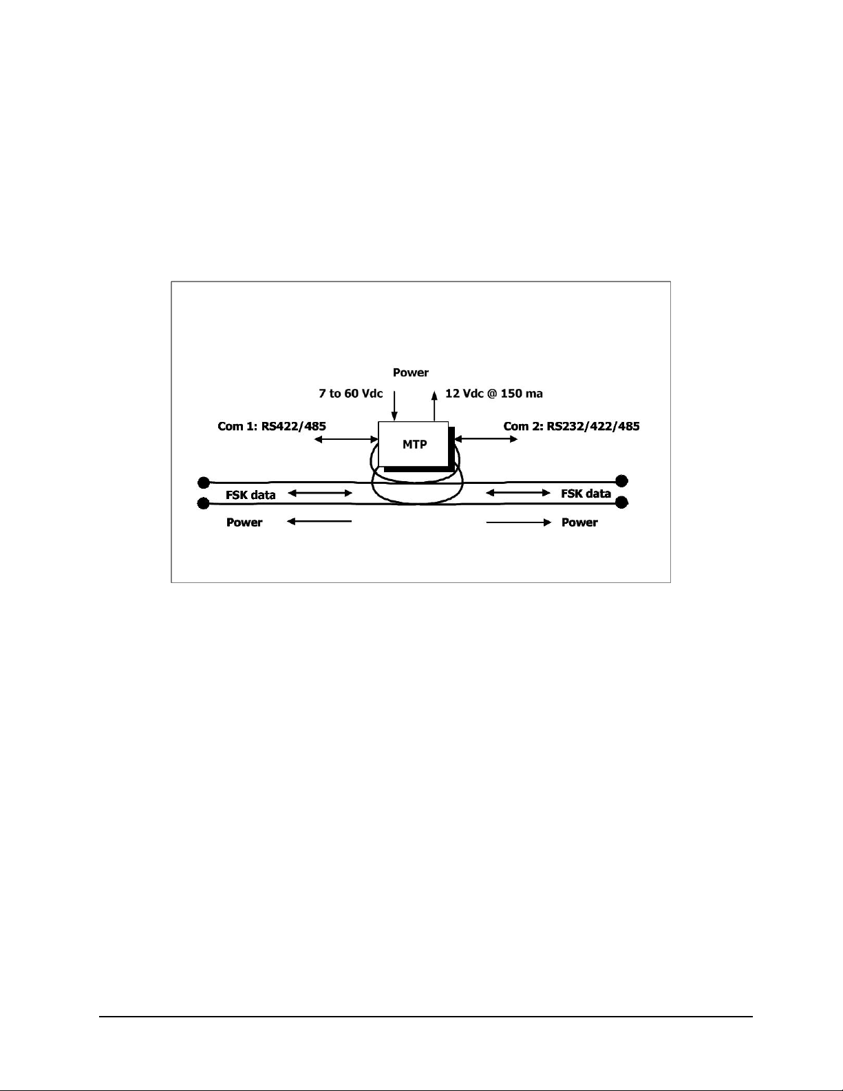
(This section will be prepared when production hardware is available)
Figure 2.a MicroTrack Processor Unit Inputs and Outputs
MicroTrack User Guide 13 April 1, 2004

3. Site Planning and System Configuration
Site planning is an essential step to ensure MicroTrack is properly applied and configured to a specific
site. Site planning includes visiting the site, assessing site characteristics and defining the basic system
configuration. Once this step is complete we can proceed to detailed system configuration and layout
which includes defining what MicroTrack system components are required and how they will be
distributed around the site. The first step in this process is performing a site survey.
3.1 Site Survey
The purpose of conducting a site survey is to determine how MicroTrack can be best applied to the site,
determine the users installation preferences and operational needs, identify site specific situations
affecting the MicroTrack installation, determine the system components required, assess the need for
auxiliary sensors and interfacing with them, and define installation parameters, including the type of
equipment required, as well as time and cost.
Prior to conducting a site survey there are a few items which should be obtained and reviewed with the
end user, site manager or person responsible for site security.
• Obtain
Determine the
• Review the drawings with the site manager and discuss preferences and options for
MicroTrack
• Determine if there are any
including weather, areas subject to flooding, snow accumulation, frequent access by staff or
public, need for auxiliary sensors, etc.
• Determine if
frequencies
• Determine if
location and coverage if installed to match zones
• Determine
how MicroTrack will be monitored or interfaced with other systems
To conduct the site survey make sure that you have the following items:
• A long tape measure – 100 ft. (33 m) length is ideal, or distance measuring wheel
• A
• This
• A
as-built drawings of the perimeter area and aerial photographs if they exist
location of services crossing the perimeter, including: water, sewer, gas and
electrical
locating
site conditions relevant to sensor positioning and performance
mobile radios and/or two-way radios are used at the site and make note of their
CCTV cameras are or will be used in conjunction with MicroTrack and note their
location of the control center and note the distance from the perimeter, and determine
camera or video camcorder (user permission may be required)
Site Survey section of the User Guide and a copy of the checklist in Appendix 2
notepad and clipboard and pen or pencil (and proper footwear depending on site conditions)
MicroTrack User Guide 14 April 1, 2004

Now you are ready to walk around the perimeter of the site, preferably with the end user, to assess
installation conditions and the best location for MicroTrack and auxiliary sensors, if required. Here are
the important steps to consider during the walk-around:
•
Select the path where MicroTrack sensor cable will be installed – typically along the inside of the
perimeter fence (or wall) or between two fences (or walls) – ideally, a distance from 10 to 15 feet
(3 to 4.5 m) from the fence. If there are no site drawings available,
perimeter
Take photographs of key features and reference where the photographs were taken on the sketch
•
or drawing
•
Walk along the perimeter corridor and make note of the location and size, as appropriate, of the
items below which are up to 20 feet (6 m) from each side of the proposed sensor cable path. Take
photographs of features during the walk and note
Measure the length of each side of the perimeter, distances between fences and buildings,
location of gates, roads, sidewalks and obstacles
Identify the
Identify the
buried less than one meter (3 ft.) deep
Identify the
- Dig small
- Measure the
- Measure the
Identify the
sensor cables (these may have to be shielded if non-metallic)
Identify areas where
erosion and runoff over the cable path
• Determine the
Contact Southwest Microwave, Inc., Technical Support, if you require assistance at:
•
type of fence, its height and types of gate (swing or sliding)
location of services including water, sewer, power, gas, telephone, which may be
burial medium along the perimeter corridor: soil, asphalt, concrete
test holes 10 in. (25 cm) deep in a few areas along the sensor cable path to
determine the
soil, etc. This will determine if sand backfill is required to cover the sensor cables
cut into the asphalt [if 3 in. (8 cm) or more] or should be installed in the soil below
that has to be saw cut for the sensor cable
location of auxiliary sensors, e.g., along the entire perimeter or only at gates
nature of the soil, i.e., is it consistent, contains rocks, debris, sand, clay
asphalt thickness (and/or concrete) to determine if the sensor cable can be
length of asphalt (and/or concrete) areas to assess the amount of material
location of culverts which may be less than one meter (3 ft.) from the buried
water runoff occurs and determine if provision must be made to prevent
Tel 1-480-783-0201, x338, Fax 1-480-793-0401
Email:
gusf@southwestmicrowave.com
make a sketch of the
MicroTrack User Guide 15 April 1, 2004

3.2 System Configuration and Layout
The second step in the site planning process is determining what MicroTrack components and how many
are required. Then we can define how they will be placed around the site.
3.2.1 Determining Total Sensor Cable Length
The first step is to determine the perimeter length of the sensor cable path. Exact measurements are
preferable. However, as a guideline, if the sensor cable set will be installed within 15 feet (4.5 m) of the
fence, for rough estimating purposes, use the total perimeter length of the fence line to estimate the total
length of sensor cable required.
Total Perimeter Length ≈ Total Sensor Cable Set Length
3.2.2 Lead-in Cable and Connectors
Each MTC400 sensor cable includes a 20 m (66 ft.) length of lead-in cable. The lead-in is factory
connected to the sensor cable and is installation-ready with factory installed TNC connectors for
connection to the MTP.
3.2.3 Determining the Quantity of Sensor Cable Assemblies per System
To determine the number of sensor cable assemblies required for a site we must first decide which length
of each cable set is preferred. There are two standard sensor cable lengths available:
MTC400-105, 105 m (344 ft.) long
MTC400-205, 205 m (672 ft.) long
Each sensor cable includes an additional five (5) meters (16 ft.) of sensor cable for a startup overlap with
the adjacent sensor cable set for the detection field to build up to its full height. Note that the five meters
used for startup are not to be counted when determining total sensor cable set length requirements. The
startup overlap is made only at the MTP.
The longer cable set is more cost effective. Note that cable sets are independent of detection zones and up
to 50 detection zones can be defined for every two sensor cable sets, i.e., 50 zones can be created of any
length for a distance of up to 400 m (1312 ft.) of sensor cable. Assuming the MTC400-205 cable
assembly is selected, the number of sensor cable sets and sensor cable assemblies required for a site is
determined as follows:
Quantity
200 m
Alternatively, if the MTC400-105 cable assembly is preferred,
Quantity
100 m
of MTC400-205 Sensor Cable Sets = Total Sensor Cable Set Length
of MTC400-105 Sensor Cable Sets = Total Sensor Cable Set Length
MicroTrack User Guide 16 April 1, 2004

Sensor cable sets can be customized on-site to any length between 10 m (33 ft.) and the maximum length
of 200 m (656 ft.). The number of cable sets should always be an even number to utilize the dual cable
set capability of the MicroTrack MTP.
Quantity
Quantity
= 2 x
3.2.4 Determining the Quantity of MicroTrack Processor (MTP) Units
Each MTP can have two MTC400 sensor cable sets, and the maximum number of MTP’s per system is
eight (8). It is possible for an MTP to have only one sensor cable set provided a MicroTrack Termination
is installed on the unused side of the MTP.
Quantity
2
3.2.4.1 Network and Standalone Configurations
MTP’s can be used in one of two configurations: either network or standalone. A network system is
where a series of MTP’s are linked together so that power and data pass from one MTP to the next
through the sensor cable.
Quantity
An even number of cable sets should be used with one or more MTP’s. Shorter length sensor cable sets
can be used to close a perimeter if using 200 m (656 ft.) cable sets exceeds the required perimeter length.
One 48 VDC power supply can power up to four (4) MTP’s. A second power supply will be required for
additional MTP’s. An FSK repeater will be required when more than five (5) MTP’s are used.
If the perimeter length exceeds the “System” limit of eight (8) MTP’s, additional MTP’s can be installed
as a “second System” with a separate power and data link with from the Map Monitor (or alternative
alarm monitoring system) in the control center. There is no need to synchronize MTP’s or MTP
“Systems”.
A system is considered “standalone” when each MTP is independently powered and communicated with
from the control center.
3.2.4.2 Redundant Power and Data System Configuration
It is possible to configure MicroTrack with fully redundant closed loop power and data communications
as shown below in Figure 3.1. This feature ensures system integrity is maintained should a sensor cable
of Sensor Cable Sets per System
of MTC400 Sensor Cable Assemblies per MTP
of MTP’s per System
≡ Number of
≡
2, 4, 6, 8, 10, 12, 14, or 16 Maximum
Quantity
of Sensor Cable Sets
Sensor Cable Sets
of MTP’s per Network System ≡ up to 8 (3.2 km or 2 miles)
MicroTrack User Guide 17 April 1, 2004
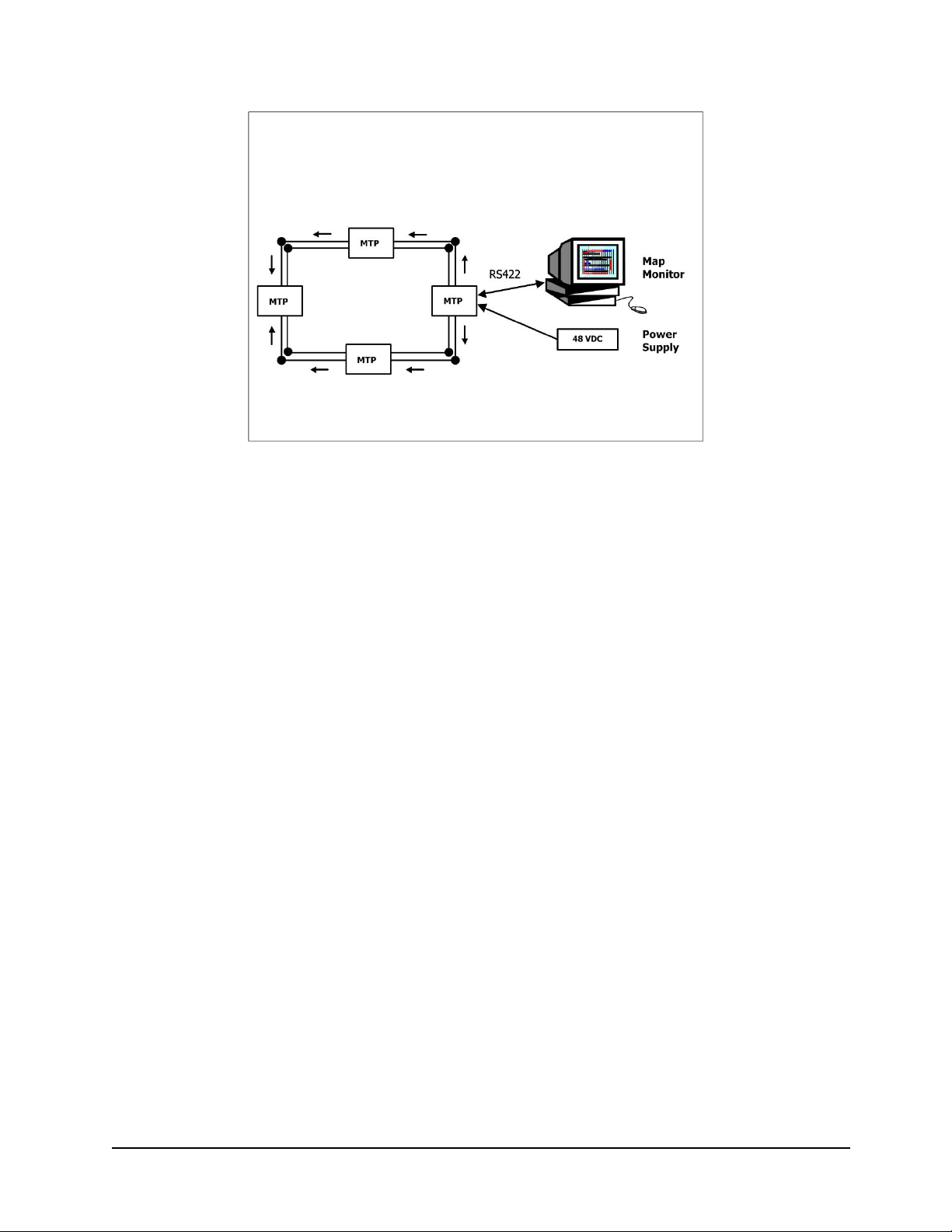
Figure 3.1 Redundant power and data configuration
be cut or damaged rendering it inoperable. In this configuration, one MTP is powered from the control
center and power and data communications are sent to the other MTP’s through the sensor cable as
illustrated below. FSK data networking is used for communications on the sensor cable between MTP’s.
Up to five MTP units can be configured with redundant power and data.
Maximum
3.2.4.3 Positioning and Powering MTP Units
The first MTP should be positioned at a point on the perimeter closest to the control center to provide best
access for power and data communications. MTP’s are usually installed on or near the perimeter fence
and can be located up to 20 m (66 ft.) from the sensor cable set. Power and data connections are made
directly to the panel of the first MTP, while adjacent MTP’s have their power and data fed from one to the
other through the sensor cables.
There are two methods of powering MTP’s to provide for smart sensor data communications, and one
method which uses each MTP as an independent standalone sensor with simple alarm relay output, i.e., no
smart sensor data communications:
Option 1: Power one MTP directly from the control center and additional MTP’s via the sensor
cable; all with smart sensor data communications via the sensor cable (maximum of four (4)
MTP’s per 48 VDC power supply, and eight (8) MTP’s per System).
Option 2: Power each MTP independently with smart sensor data communications via the sensor
cable (eight MTP’s per System)
Option 3: Power each MTP independently and have separate and simple relay alarm output, i.e.,
the smart sensor data communications capability is not used.
Quantity
of MTP’s per Redundant System
≡ 5 (2 km or 1.25 miles)
MicroTrack User Guide 18 April 1, 2004

3.2.5 Determining the Quantity of Systems per Map Monitor
Up to eight (8) complete MicroTrack systems can be connected to one Map Monitor. Each system can
have a separate site map associated with it.
Quantity
3.2.6 Adding Auxiliary Sensor Inputs and Outputs to MTP’s
MicroTrack’s integral power and data capability can also provide output power and data communications
for auxiliary sensors. A list of typical inputs and outputs are as follows:
• Outdoor intrusion detection sensors, at gates, sallyports, roads or complete perimeter, such as:
Microwave at gates
MicroPoint fence disturbance sensor – a smart sensor
• Gate entry barriers and access control points
• Interior intrusion detection sensors, including alarm panels
• Perimeter lighting
• Closed circuit television cameras (CCTV), e.g., input to PTZ control
The following options are available for power and data communications with auxiliary sensors:
• Sensor Interface Module (SIM) – 8 relay inputs, 8 relay outputs, output power 12 VDC @ 150
ma, communications via RS232/422/485
• Sensor Multiplex Module (SMM) – 8 relay inputs, communications via RS485
3.2.7 When to use a Relay Module (RM)
Relay Modules are used to communicate with auxiliary sensors and other devices on the perimeter. Each
RM provides for six (6) relay inputs, six (6) contact outputs and four (4) analog inputs to various devices.
RM’s receive power from and communicate directly with an MTP. A maximum of 15 RM’s may be
connected to one MTP.
3.2.8 Sensor Cable Installation Components
Installation components are required to link sensor, terminate and repair cable sets. The following section
describes where they are used and how they are selected.
of MicroTrack Systems per Map Monitor
≡ up to 8
MicroTrack User Guide 19 April 1, 2004

3.2.8.1 Determining the Quantity of MicroTrack Links (MTL)
MicroTrack Links connect sensor cable assemblies from the “A” side of one MTP to the “B” side of the
next MTP. One MTL is required for each sensor cable assembly. Therefore, a total of four (4) MTL’s
are required for each MTP.
Quantity
3.2.8.2 Determining the Quantity of MicroTrack Terminations (MTT)
An MTT is used at the end of each sensor cable assembly when there is no adjoining sensor cable set, i.e.,
the system is open loop.
Quantity
3.2.8.3 Determining the Quantity of Splice Kit (MTS)
Splice kits are used to repair a damaged section of sensor cable and should be ordered as a back-up item.
It is recommended to have at least two splice kits available should a sensor cable set incur damage, one
kit to repair each cable. Spare sensor cable will also be required and a minimum quantity of 50 m (164
ft.) is recommended.
of MTL’s per Sensor Cable Assembly = 1
of MTT’s per Sensor Cable Assembly = 1
MicroTrack User Guide 20 April 1, 2004

3.3 Sample System Configuration – A Four MTP Redundant Closed-loop System
The system shown in Figure 3.2 will be used to define the components and quantities required to order a
complete MicroTrack System.
Figure 3.2 Sample Configuration of a Four MTP Redundant Closed-loop System
Item Model No. Description Quantity
1 MTP
2 MTE-ME
3 MTC400-205
4 MTL
5 PS48
6
01A15028-A01
7
8
9 MTS
10 MTC400
MicroTrack Processor Unit 4
Weather-tight Enclosure - metallic 4
MicroTrack Sensor Cable Assembly, 205 m (672 ft.) 16
MicroTrack Link 16
Power Supply 120VAC to 48 VDC 1
Intrepid Map Monitor Software License – version 4.0 1
Modem Kit for Remote Service 1
Standard PC with Microsoft Windows 2000 or XP 1
Splice Kit 2
Sensor Cable - spare 50 m
11
Data and Power Cable, as required TBD
MicroTrack User Guide 21 April 1, 2004

3.4 Sample System Configuration – A Two MTP Open Loop System with Auxiliary
Sensors
The system shown below in Figure 3.3 will be used to define the components and quantities required to
order a complete MicroTrack System.
Figure 3.3 Sample Configuration of a Two MTP Open-loop System with Auxiliary Sensors
Item Model No. Description Quantity
1 MTP
2 MTE-ME
3 MTC400-205
4 MTL
5 MTT
6 PS48
7
8 RM
01A15028-A01
9
10
MicroTrack Processor Unit 2
Weather-tight Enclosure - metallic 2
MicroTrack Sensor Cable Assembly, 205 m (672 ft.) 8
MicroTrack Link 8
MicroTrack Termination 4
Power Supply 120VAC to 48 VDC 1
Intrepid Map Monitor Software License – version 4.0 1
Relay Module 1
Modem Kit for Remote Service 1
Standard PC with Microsoft Windows 2000 or XP 1
11 MTS
12 MTC400
13
Splice Kit 2
Sensor Cable - spare 50 m
Data and Power Cable, as required TBD
MicroTrack User Guide 22 April 1, 2004

4. System Design
This section will provide guidance on how to design a MicroTrack System. It includes information on
sensor performance characteristics, selecting cable spacing and positioning, how the sensor cables should
be installed in different burial mediums, how to deal with various site environmental conditions, and how
to layout the sensor cables.
4.1 System Design Parameters
System design addresses the key application parameters to apply MicroTrack to a wide variety of sites.
This includes optimum sensor cable spacing, proximity to fences, installation in different burial mediums,
environmental effects, animals, uneven terrain, concertina and razor tape, vehicles, buildings and
obstacles, culverts, detection field startup and turning corners.
4.1.1 Selecting the Optimum Sensor Cable Spacing and Position Near Fences
One of the first steps of system design is to select the optimum sensor cable spacing for the site. Sensor
cable spacing is primarily site dependent and based on a combination of the following parameters:
• Proximity to fences, buildings, roads, sidewalks and passers-by
• Burial medium characteristics, e.g., type of soil, concrete, asphalt, etc.
• Environmental conditions such as frost
Before we go into detail on how to optimize cable spacing it is important to identify a characteristic of
MicroTrack’s detection field. MicroTrack is designed to detect human intruders crossing its primary
detection field, as shown below in Figure 4.1. It can also detect larger objects, such as vehicles, with its
secondary detection field.
Figure 4.1 MicroTrack Detects Both People and Vehicles
MicroTrack User Guide 23 April 1, 2004

It is important to recognize the existence of this secondary field because it governs the safe distance from
which MicroTrack can be positioned from fences, buildings and roads without interference and potential
nuisance alarms.
Cable spacing for MicroTrack can range from 1 to 2 meters (3.3 to 6.6 feet). Since the detection field
extends approximately 50 cm (20 inches) on each side of the sensor cable the total detection field width
can range from 2 to 3 m (6.6 to 10 feet) as shown below in Figure 4.2. The detection field height remains
constant at one meter (3.3 feet) over this range of cable spacing.
Figure 4.2 MicroTrack Detection Field and Cable Spacing Range for Various Burial Mediums
Narrower cable spacing has the advantage of permitting MicroTrack to be installed in more restrictive
areas, such as between closely spaced fences and between a fence and a building - with a low potential for
nuisance alarms. A wider detection field increases the probability of detection for running and jumping
intruders.
The key site dependent factors which dictate cable spacing are presented below.
Proximity to Fences and Fence Types
The first parameter to consider in determining sensor cable spacing is the proximity to a metal fence. It is
important that MicroTrack be located at the right distance from a metal fence to avoid nuisance alarms
and to avoid detection at or beyond the fence. Generally, the higher the mechanical and electrical
integrity of the fence the closer the sensor cable can be located.
It is the electrical characteristics of the fence which are most important to MicroTrack. Fences which are
constructed of solid fabric, such as welded mesh, palisade or expanded metal the create the lowest
electrical noise. Chain link mesh fences are often a source of electrical noise, especially if the mesh is
poorly tensioned and the post and rails move with wind action or thermal effects, and therefore can be a
source of nuisance alarms if MicroTrack is too close to the fence.
MicroTrack User Guide 24 April 1, 2004

Non-metallic fences, such as wooden fences or PVC fences, can be placed closer to or within the
detection field without any affect on nuisance alarm rate. However, it is important to consider position of
the fence and detection field with respect to nearby roads and passers-by to ensure they are not detected.
Table 4.1 provides guidelines for fence proximity based on fence condition and soil conductivity. More
information on effect of burial medium conductivity is presented below.
Fence Type (Metal)
Highly tensioned or
rigid fabric
Low tensioned with
loose fabric
Distance between Fence and Sensor Cable for
Low and High Conductivity Burial Mediums
Low Conductivity
(sandy soil, asphalt, concrete)
0.1< σ<1.0 mS/m (TBD)
3 m (10 feet) 2 m (6.6 feet)
4 m (13 feet) 3 m (10 feet)
High Conductivity
(high clay content soils)
1.0< σ<30 mS/m (TBD)
Table 4.1 Typical Distances between Metal Security Fences and Sensor Cable
(measured from fence to closest sensor cable)
Burial Medium Conductivity
Burial medium conductivity is the next key parameter in determining cable spacing. Burial medium
conductivity affects detection field size. Low conductivity which is typical of light sandy (silica based)
soils tend to produce a very large detection field compared with high conductivity burial mediums (high
clay or mineral content soils) which create a more standard size detection field. Concrete and asphalt also
usually have a low conductivity depending on the type of aggregates used.
Soil conductivity should be evaluated at various locations along the proposed cable path to determine
cable spacing and position with respect to fences and other objects. Soil samples should be collected
from a depth of 15 to 20 cm (6 to 8 inches) below the surface. Conductivity can be easily measured on
site (there are many commercially available devices) or samples can be taken and provided to a testing
laboratory for analysis.
Site Environment and Occurrence of Frost
The last key parameter in determining cable spacing, site environment, is important in regions where deep
ground frost occurs, i.e., frost down to or deeper than the sensor cables. Ground frost has the effect of
significantly changing the soil permittivity (by an order of magnitude) such that the detection field
becomes very large compared to the size of the detection field when the ground is frost-free. The
opposite effect occurs when frozen ground completely thaws-out – the detection field will diminish in
size. So frequent calibration checks are important for sites having deep frost conditions. There are other
site environment parameters, such as rain, snow, ice, and ground moisture content to consider, however,
deep ground frost has the greatest effect. Water, particularly moving water, is another parameter of
MicroTrack User Guide 25 April 1, 2004

importance which will be addressed in a subsequent section. Deep snow has the effect of slightly
enlarging the detection field. However, snow should not be allowed to build up to such a depth as to
enable an intruder to tunnel under the snow. While MicroTrack will detect and identify the location of
the intruder, it will be difficult to assess and verify an intrusion with CCTV. A summary of the key
factors affecting cable spacing is presented below in Table 4.2.
Cable Spacing Determinants
Site Parameters –
in Order of Priority
1 to 1.5 m (3.3 to 5 ft)
Narrow
Wide
1.5 to 2 m (5 to 6.6 ft)
1. Sensor proximity to fence(s)
2. Burial medium conductivity
3. Site environment
Table 4.2 Sensor Cable Spacing is Determined by a Combination of Factors
It is important to create a uniform detection field to ensure that the probability of detection is maintained
and optimized with respect to the nuisance alarm rate. While it may appear that a larger detection field is
preferable, it is not, because the larger field may be affected by fence generated electrical noise, greater
sensitivity to nearby road traffic and environmental changes. Figure 4.3 illustrates guidelines for a typical
site with a high security chain link fence and medium to low conductivity soil where frost would occur.
Close – 2.5 to 3 m (8 to 10 ft) Far – > 3 m (10 ft)
Low to medium
0.1< σ<1.0 mS/m (TBD)
Frost Frost-free
Medium to high
1.0< σ<30 mS/m (TBD)
Figure 4.3 MicroTrack Detection Field Proximity to Fences and Roads for Typical Site Conditions
MicroTrack User Guide 26 April 1, 2004

4.1.2 Double Fences , Concertina and Razor Tape
Double fences are often used at high security sites and MicroTrack is usually installed between the
fences. At correctional sites, it may be desirable to install MicroTrack inside the inner fence to provide an
advanced warning of an escape attempt, depending on the availability of space. In some cases, it may be
preferable to install MicroTrack both inside the inner fence and between the fences.
Many high security sites use barbed concertina wire or razor tape on fence tops, as well as stacked on the
ground, as illustrated below in Figure 4.3. Concertina and razor tape can cause electrical noise as a result
of wind action or thermal changes if placed to close to MicroTrack. For this reason it would be best not
to install razor tape between the fences unless there is sufficient space to position MicroTrack. Should it
be necessary to install razor tape between the fences the same distance rules for spacing the sensor cable
from a fence would apply to the razor tape.
Figure 4.4 MicroTrack Detection Field between Fences for Typical Correctional Site
4.1.3 Animals and the Detection Field
Large animals, such as deer, horses and large dogs, can also be detected by MicroTrack. Therefore,
fencing would be required to keep animals away from the detection field if nuisance alarms from these
sources are to be avoided. Small animals, such as birds, rabbits, marmots, and small dogs, will not be
detected by MicroTrack. The reason they are not detected is because their body mass, particularly their
water content, i.e., their electromagnetic cross-section, is so small that they are not seen by MicroTrack.
While larger animals with a body mass equal to or larger than an adult human will be easily detected.
MicroTrack User Guide 27 April 1, 2004

4.1.4 Cable Spacing Near Buildings
One of the unique features of MicroTrack is its ability to accommodate restrictions such as narrower
spaces, as illustrated below in Figure 4.5. This example shows a building intruding into the secure area
between fences. To accommodate this narrower space, the sensor cable spacing can be reduced by
approximately two-thirds. Thus, if the cable spacing was 1.5 m (5 feet) before the building, then it can be
gradually reduced to approximately 1 m (3.3 feet) starting about 3 m (10 feet) before the building. The
cable can be restored back to its former spacing after the building if space permits, as shown below.
Figure 4.5 Reducing Sensor Cable Spacing for Narrower Spaces
4.1.5 Accommodating Grass, Trees and Shrubs
MicroTrack can be installed in and around a wide variety of vegetation including lawns, field grass, trees
and shrubs. While most high security sites will have a sterile area where no trees or vegetation is
permitted, there are numerous sites with various forms of vegetation which must be accommodated.
Installing MicroTrack under lawns where grass is kept short by routine mowing is ideal. Areas where
grasses are allowed to grow wild and tall will not affect MicroTrack’s detection performance. However,
if tall grasses, 30 cm (1 foot) or more, accumulate moisture from dew or rain and move do to wind action,
nuisance alarms are possible. Tall grasses create a security assessment problem because they could allow
an intruder to hide unseen.
If necessary, MicroTrack can be installed close to large shrubs. However, nuisance alarms could occur if
the shrubs have large leafy moisture laden branches and move with the wind. Detection performance
should not be affected, although assessment could be compromised by providing cover for an intruder.
MicroTrack can also be installed close to and around trees, large or small as shown below in Figure 4.6.
A concern with installing sensor cables close to trees is the potential damage to the tree(s) root system
MicroTrack User Guide 28 April 1, 2004

resulting from trenching. To avoid damaging roots, trenches can be hand dug and the sensor cable
threaded under or around the roots of the tree.
Unlike seismic sensors, the motion of a tree or its roots should not cause nuisance alarms because their
rate of motion is much too slow to affect MicroTrack’s electromagnetic field. However, should large
leafy branches move rapidly due to wind action within the detection field, or break and fall into the
detection field, nuisance alarms could occur. Detection performance will not be affected by the presence
of trees within or close to the detection field. While it is preferable not to have trees close to a secure area
because they limit assessment, MicroTrack can be easily adapted to such sites.
How far should MicroTrack sensor cables be installed from trees and shrubs? There is no universal rule,
however, unless there is no alternative, a minimum of 1 m (3.3 feet) is preferable for leafy shrubs. The
distance from trees depends more on the practicality of installing under or around tree roots. Sensor
cables can be installed around one side of the tree, or if there is insufficient space they can be divided so
that one cable goes around each side of the tree.
Figure 4.6 Routing Sensor Cables Around Trees, Shrubs and Buildings
4.1.6 Uneven Terrain
MicroTrack is a terrain following sensor so it can be easily adapted to sites with uneven terrain as
illustrated below in Figure 4.7. It is preferable to avoid abrupt changes in slope so that the detection field
can develop smoothly along the cable path. Abrupt changes of more than 30 degrees may reduce
detection field height or cause gaps near the ground depending on the direction of slope change.
MicroTrack User Guide 29 April 1, 2004

Figure 4.7 MicroTrack Detection Field is Terrain Following and Goes Up and Down Hills
4.1.7 Rain, Standing Water and Run-off
Rain falling through the detection field will not adversely affect detection performance nor cause nuisance
alarms. The issue to be concerned about rain is what happens to all the water after it reaches the ground.
If water is allowed to accumulate into large puddles (larger than 1 to 2 m [3.3 to 6.6 feet] across) over the
sensor cables two events are likely to occur. First, large drops from heavy rain will cause the puddles to
Figure 4.8 Encouraging water runoff reduces potential nuisance alarms from moving water
MicroTrack User Guide 30 April 1, 2004

be disturbed, and, secondly, strong wind could cause wave action on the puddles. Both effects could
generate nuisance alarms. There are a variety of solutions to either completely avoid or at least minimize
this problem.
To prevent the accumulation of water over the sensor cable it is recommended that the ground surface be
either slightly crowned or sloped as shown above in Figure 4.8. In areas where puddles cannot be
avoided, it is recommended that crushed stone be applied over the surface to either eliminate puddles or
minimize puddle surface area. The most desirable solution, if possible, is to provide drainage to allow the
water to drain away from the sensor cable area.
It is important to note that standing water is not a problem for MicroTrack, and neither is having the
sensor cables installed in a totally saturated burial medium, e.g., mud. The problem is having moving
water near the sensor cables! Since MicroTrack detects objects which have a certain electromagnetic
cross-section and have motion, large bodies of water moving close to the sensor cables exhibit similar
characteristics and could cause nuisance alarms. Therefore, having running water, such as stream moving
across or along the sensor cable path is to be avoided.
4.1.8 Burying Sensor Cables in Soil
MicroTrack sensor cables are usually directly buried in soil as shown below in Figure 4.9. Trenches are
dug with a mechanical walk-along or ride-on trencher. They can also be direct buried using a vibratory
plow. Rocks should be removed from the trench to avoid damaging the cable. Also, if sharp rocks are
present it is advisable to place screened soil around the cable to prevent mechanical damage. This is
especially necessary where frost action may move rocks and sharp stones into the cable.
The tolerance for cable depth is ±2.5 cm (1 inch) and cable spacing is ±5 cm (2 inches). While it is
recommended to maintain these tolerances, minor deviations will be compensated by the sensitivity
leveling calibration technique.
Figure 4.9 MicroTrack Sensor Cable Burial in Soil
MicroTrack User Guide 31 April 1, 2004

After the trench is made it should be inspected to check depth and to remove rocks and debris. It is very
important that metal objects be removed from the immediate area (up to 1 m [3 feet]) from where the
cables will be installed as these could be a potential source of nuisance alarms.
The sensor cable is supplied on 60 cm (2 foot) diameter wood spools containing either 105 or 205 m (344
or 672 feet) including a 20 m (66 feet) section of lead-in cable. The lead-in includes factory installed
TNC connectors, therefore no connectors are installed in the field. The far end of the cable is trimmed to
length and is either terminated with a MicroTrack Termination (MTT) for a single cable set, or joined to
the next sensor cable set with a MicroTrack Link (MTL). Details on these components and how to
connect them are provided in Section 5.
The cable should be laid loosely in the trench starting from the MTP with the lead-in cable. There is no
need to tension the cable. After both cables are spooled-off the trench can be partially backfilled. This is
best done by hand with a garden or landscape rake. Then yellow plastic “caution tape” can be laid on the
soil and the remaining soil backfilled into the trench using a plow or by back dragging a bucket loader.
Avoid driving directly on the cable trench. Additional details on how to layout the trenches and install
the cable is provided below in Section 5.
4.1.9 Burying Sensor Cables in Concrete or Asphalt with a Thickness
There are two methods of burying MicroTrack sensor cables in concrete and asphalt depending on the
thickness of each material. When the thickness is greater than 10 cm (4 inches), the materials can be
slotted with a concrete saw and the sensor cable installed directly in the material, as shown below in
Figure 4.11. In general, concrete and asphalt are considered to have low conductivity, depending on the
aggregates used.
≥
10 cm (4 inches)
Figure 4.11 MicroTrack Sensor Cable Installation in Concrete (or Asphalt) over 10 cm (4 in.) thick
MicroTrack User Guide 32 April 1, 2004

The saw cuts are made with a walk-behind concrete and pavement saw. Concrete dust and debris should
be removed from the saw cut with compressed air jet. Then the slot should be treated with a concrete
sealer. The cable is then laid at the bottom of the slot and covered with a 16 mm (5/8 inch) diameter foam
backer rod which serves to hold the cable at the bottom of the slot and provides a waterproof barrier. A
high quality traffic grade sealant is applied to provide a waterproof seal over the concrete and backer rod.
There are several varieties available, such as Gold Label Loop Sealant and Bondo P-606 Flexible Sealer.
A gap of at least 13 mm (1/2 inch) should remain between the top of the backer rod and the top of the slot
to allow for adequate bonding of the sealant.
The saw cut can be either 45 mm (1.75 inches) deep, as shown above, which is recommended for
reinforced concrete, or 60 cm (2.4 inches) deep for non-reinforced concrete. The deeper slot will require
the use of two 16 mm (5/8 inch) diameter foam backer rods to fill the additional depth.
The same approach applies to asphalt surfaces with a thickness greater than 10 cm (4 inches).
4.1.10 Burying MicroTrack Sensor Cables in Concrete or Asphalt with a Thickness
cm (4 inches)
When the thickness of the concrete or asphalt is less than 10 cm (4 inches) it is best to cut completely
through the materials to install the cables in the soil below as shown in Figure 4.12. The material is saw
cut to a width of approximately 25 to 30 cm (10 to 12 inches) depending on the base materials. The larger
width is recommended when there is a deep base of crushed stone.
The concrete or asphalt can then be removed and disposed of. A trencher can be used to excavate the
crushed stone and soil to the depth of 20 cm (8 inches) below the concrete or asphalt. If there is only
crushed stone at that depth the trench should be made deeper, up to 30 cm (12 inches) deep, and
backfilled with soil so that the cable is installed in soil at the specified depth. If necessary, geotextile
fabric can be used to stabilize the soil and prevent it from sifting into the crushed stone.
<
10
Figure 4.12 MicroTrack Sensor Cable Burial in Asphalt (or Concrete) less than 10 cm (4 in.) thick
MicroTrack User Guide 33 April 1, 2004

The sensor cable should be partially backfilled and “caution tape” installed between the soil and crushed
stone. The trench can then restored by patching the asphalt or concrete to match the top surface.
Figure 4.13 MicroTrack Sensor Cable Can be Buried in a Variety of Mediums
4.1.11 Burying MicroTrack Sensor Cables in a Variety of Installation Mediums
As shown above in Figure 4.13, MicroTrack sensor cable can be buried in a variety of mediums while
providing a detection field with uniform sensitivity. Variances in burial medium characteristics are
compensated by MicroTrack’s unique sensitivity leveling calibration technique which will be introduced
in the Section 6.
4.1.12 Bypassing Large Non-metallic Drainage Pipes and Culverts
When large non-metallic drainage pipes or culverts (over 10 cm [4 inches] in diameter) are located within
one meter (3 feet) of the sensor cable they should be shielded so that water flowing through them will not
be detected by MicroTrack. This could occur from water surges, i.e., when water rapidly begins or stops
flowing. This effect would not be sensed by MicroTrack in metallic pipes or culverts which provide their
own shielding.
There are two methods to provide shielding. If the pipes are small diameter, i.e., up to 15 cm (6 inches),
it may be more practical to wrap them in a metal foil, preferably one which has a plasticized coating to
prevent corrosion. Larger pipes and culverts should be shielded using a large sheet of metal, such as
galvanized steel, as shown below in Figure 4.14. Note that the shielding should extend to the bottom of
the pipe.
MicroTrack User Guide 34 April 1, 2004

Figure 4.14 Metal shielding over Non-metallic Culvert
The shielding should also extend over the pipe or culvert for a distance of one meter (3 feet) to each side
of the sensor cable path as shown below in Figure 4.15. It should be a continuous piece of metal or if
multiple sections are used, they should be fastened together to ensure there are no loose metal contacts
between the sections which could generate electrical noise.
Figure 4.15 Metal shielding over Non-metallic Culvert - Side View
MicroTrack User Guide 35 April 1, 2004

Small pipes, such as those used for irrigation and sprinkler systems should not cause any interference with
MicroTrack. However, if MicroTrack is installed within the range of an operating water sprinkler head
nuisance alarms may occur when the system starts and stops. Nuisance alarms are not likely to occur
while the sprinkler system is operating, assuming the sprinklers are providing a fine uniform spray.
4.1.13 Buried Electrical Cables, Conduits and Wires
The presence of electrical cables either buried directly in the ground or installed in metal conduits should
not have any adverse effect on MicroTrack if they are located one meter (3 feet) or more from the sensor
cable, which is the minimum depth they are usually permitted by building codes. However, if electrical
conduits are buried within one meter (3.3 feet) of the cable, it is important that they be mechanically well
connected so that there are no intermittent contacts which could be sensed by MicroTrack.
Should any cables, conduits or wires be located near the sensor cables they may locally alter the detection
field depending on their orientation. If they are perpendicular to the sensor cable they should not
adversely effect performance, and should variances occur they would be compensated through sensitivity
leveling during system calibration.
Cables, conduits or wires running parallel to the sensor cable may degrade performance and should be
kept 2 m (6.6 feet) away from the sensor cables.
4.1.14
Overhead electrical cables and wires should not have any effect on MicroTrack if they are located more
than 2 m (6.6 feet) above the ground. Conduits, unless they are mechanically well connected, could cause
nuisance alarms if they are located within the secondary detection field.
4.1.15 Lead-in and Sensor Cable Startup – Linear
Lead-in cables are used to link the MicroTrack Processor (MTP) electronics to the sensor cable. The
lead-in cable is 20 m (66 feet) long and are factory spliced to the sensor cable. It is a double shielded
cable so RF energy will not escape before it reaches the sensor cable. Each MTP supports two sensor
cable sets, one that goes to the right, and the other goes to the left. Since the detection field takes
approximately 4 meters (13 feet) from the start of the sensor cable to develop to its full height and width.
the two cable sets must be overlapped for a distance of 8 meters (26 feet) to provide a continuous
detection field, as shown below in Figure 4.16.
Overhead Electrical Cables and Conduits
MicroTrack User Guide 36 April 1, 2004

Figure 4.16 Sensor Cable Overlap for Detection Field Startup at MTP (Side view)
This figure shows a side view of how the detection field starts and develops to full height and width over
the overlap distance. The sensor cables for each cable set are in fact buried at the same depth, although
they are drawn separately for clarity. However, the sensor cables from the A side are separated
horizontally from the sensor cables on the B side by a distance of 30 cm (12 inches). This is better
illustrated below in Figure 4.17.
Figure 4.17 Sensor Cable Overlap to Achieve full Detection Field Height at Startup(Plan view)
MicroTrack User Guide 37 April 1, 2004

The lead-in cables to the MTP can be positioned in the triangular format as shown above in Figure 4.17,
or in a rectangular pattern. The lead-in trenches must be at least 7 m (23 feet) long to ensure there is no
RF feedback from the sensor cables back to the MTP from the lead-in cable. The lead-in cable is a fixed
length and cannot be shortened. Excess lead-in cable must be buried in the lead-in cable trench in a
zigzag pattern or coiled and buried in the ground. The lead-in cable is not to be overlapped with the
sensor cable.
Figure 4.18 Lead-in Cable Crossing under Sensor Cable at Start-up
Where lead-in cable crosses sensor cable it must be buried under the sensor cable by at least 10 cm (4
inches), as shown in Figure 4.18.
4.1.16 Lead-in and Sensor Cable Startup – Corner
When an MTP is located in the corner of a perimeter a different startup approach is used, as shown below
in Figure 4.19. In this example, the first 4 m (13 feet) of each sensor cable set is positioned so that at the
point of intersection of the two cable sets the detection field from each cable set will have developed to its
full height and width.
The system illustrated below shows a very confined startup area at a site with double fencing. When
there is only one fence it may be possible to spread out the startup area which would make it easier to
trench and backfill. Note that all lead-in cables are located in separate trenches located at least 30 cm (12
inches) apart. The sensor cable spacing for the startup section should be at least 1 m (3.3 feet) wide up to
the cross-over.
Cables which cross over each one another should be separated by at least 10 cm (4 inches) as shown
above in Figure 4.18.
MicroTrack User Guide 38 April 1, 2004

Figure 4.19 Sensor Cable Overlap with a Corner Located MTP Between Double Fences
4.1.17 Making Turns with Sensor Cables
Sensor cables can be turned around corners and obstacles in either a smooth continuous curve or in
incremental steps. When MicroTrack sensor cables must turn a corner, it is important to keep in mind
that it is not only the sensor cable which must be turned but also the detection field. While it may be
possible to rapidly turn the sensor cable, it is not possible to rapidly turn the detection field. For this
Figure 4.20 The Do’s and Don’ts of Turning Corners with Sensor Cable
MicroTrack User Guide 39 April 1, 2004

reason, the sensor cable must be turned a rate which will allow the detection field to follow the cable path
and not cause it to skew away from the cable path and into other objects.
Figure 4.20 illustrates the right and wrong way to make a 90º turn. In the diagram on the left, notice how
the detection field closely follows the sensor cable when it is turned along a 6 m (20 foot) radius. While
the detection field flows slightly away from the cable during the turn it soon returns to follow the cable
after the turn.
However, in the diagram on the right, a sharp right-angle turn is made which causes the detection field to
skew past the cable and run into the fence before eventually realigning itself with the cable path. This
should be avoided because not only could the fence now cause nuisance alarms, but detection will likely
occur beyond the perimeter fence.
Another method to turn sensor cables around corners is to take short step turns. Depending on the turning
space available, step turns of up to 30º can be taken, as shown below in Figure 4.21. The minimum
distance between multiple steps should not be less than 3 m (10 feet), based on the inside step distance as
shown below.
Figure 4.21 Making Sensor Cable Corners with 30° Step Turns
In terms of site planning and distances between MTP’s, keep in mind that the outer cable will need to be
longer than the inner cable. For example, with a turning radius of 6 m (20 feet), the outer cable will need
to be approximately 2.5 m (8 feet) longer than the inner cable. Hence, if
one cable set is used on a small perimeter where there may be four 90º corners, make sure that the length
of the outer cable is accounted for, e.g., four 90º turns would result in a difference in length between the
outer and inner cables of approximately10 m (33 ft).
It is always preferable to make gentle continuous turns when changing direction. This provides better
control over the path of the detection field. The difference between continuous and multiple step turns for
a double fence configuration is illustrated below in Figure 4.22. Note that the distance between the inner
sensor cable and the fence corner for the three-step turn should not be less than 1 m (3.3 feet).
MicroTrack User Guide 40 April 1, 2004

An simple way to layout the three step turn is to stake-out a 90º radius turn and then divide the quadrant
in half, as shown above in Figure 4.21. Straight lines can then be drawn between the two halves which
represent the first and second 30º steps.
Figure 4.22 Turning Sensor Cable Around 90° Corners between Double Fences
4.1.18 Terminating the Sensor Cable Near Buildings
MicroTrack sensor cables should be terminated well before a building, gate or fence, so that the detection
field does not continue into the object. Otherwise, nuisance alarms may occur, for example, from people
moving inside the building or from metal objects on or within the building.
When the sensor cable set is terminated away from the building as shown below in Figure 4.23, a gap will
remain between the detection field and the building. Unless another MicroTrack sensor cable set is
overlapped with the end of the detection field illustrated below, it is recommended that a microwave
transceiver unit or a dual microwave/infrared sensor be installed to fill the detection gap up to the
building.
The microwave unit could be connected directly to a MicroTrack MTP or RM for power and data, so that
it is fully integrated with MicroTrack.
MicroTrack User Guide 41 April 1, 2004

Figure 4.23 MicroTrack Sensor Cable Termination Near Building with Microwave Auxiliary Sensor
MicroTrack User Guide 42 April 1, 2004

5. MicroTrack Installation
This section will describe how to layout and install MicroTrack sensor cables, sensor cable components
and MicroTrack electronics.
5.1 Staking-out the Location of MicroTrack Components on the Perimeter
This section will outline the steps for positioning the MicroTrack Processors (MTP’s), laying out the
sensor cable sets, MicroTrack Links (MTL) and MicroTrack Terminations (MTT) along the perimeter.
a. Identify the location of each MTP around the perimeter according to the criteria set out in
Section 3.2.4. Measure the distance between adjacent MTP’s to make sure they will not
exceed the length of the two cable sets which will be installed between the MTP’s.
b. Stake-out the start and end points for each sensor cable set starting from the first MTP.
i) Outer sensor cable. Stake the outer sensor cable start point centered at each
MTP. Then stake the corner points and the end points where MTL’s will be
installed (usually mid-way between the MTP’s). Stake the position of the cable
closest to the perimeter fence first. The position of this cable is based on the
criteria set out in Section 4.1.1.
ii) Inner sensor cable. Stake the location inner sensor cable based on the sensor
cable width selected. Stake the start points at each MTP, corner points and the
end points, as above.
iii) Stake-out the corner details based on either an arc radius turn or 30º step-turns
described above in Section 4.18. Use several stakes to define the corners.
c. Stake-out the lead-in cables for the A side and B side for each cable set. See example shown
in Figure 5.6.
d. Stake-out the startup area where adjacent cable sets overlap each other. Be sure to keep a
minimum separation distance (horizontally) of at least 30 cm (1 foot) between the lead-in
cables and sensor cables. Use stakes to mark each change of direction.
e. Now connect the stakes along each cable path with mason’s line. One cable set at a time.
Ensure the line(s) are taut, then using surveyor’s marker paint (or a paint wheel), paint along
each line to identify exactly where the trenches are to be made. Repeat steps b. through e. for
each cable set.
f. Remove the mason lines but leave the stakes in place to make it easier for the trenching
operator to provide a line-of-sight. (Remove and set aside each stake as the trencher
approaches.)
g. Now stake-out the path for the power and data lines from the first MTP to the control center.
If there are more than four (4) MTP’s, an additional power supply must be installed, and an
MicroTrack User Guide 43 April 1, 2004

additional trench may be required. Also, if auxiliary sensors will be installed the paths for
power and data lines will need to be staked-out.
5.2 Installing MicroTrack Processors (MTP)
The front panel of a MicroTrack Processor with its key interface points is shown below in Figure 5.1.
Figure 5.1 MicroTrack Processor Front Panel
5.2.1 Positioning the MTP
MTP’s must be located within the 20 m (66 ft.) length of the lead-in cables and outside the detection field.
This distance accounts for the branching-out to the detection field startup overlap, the vertical distance to
the enclosure, and the loop around the MTP to the TNC connection points. Typically, MTP’s are located
within 3 m (10 ft.) of the sensor cables.
5.2.2 Installing the MicroTrack Enclosure (MTE) and Protecting Cables
MTP’s are installed in a weather-tight MicroTrack Enclosure (MTE) as shown below in Figure 5.2.
Several enclosure options are offered, as listed above in Section 1.5.2. The MTE can be mounted directly
on a perimeter fence post or on a freestanding post near the perimeter with the hardware provided. A predrilled mounting plate and fasteners are included to mount the MTP within the enclosure.
The MTE is sized to provide sufficient space to loop the lead-in cables around the MTP to facilitate
connecting them to the MTP. Alternatively, a user supplied equivalently rated NEMA 4 or IP65
enclosure may be substituted. MTP’s can also be mounted in: a) a pedestal enclosure of the type
MicroTrack User Guide 44 April 1, 2004

commonly used by the telephone and CATV industry, b) a nearby building, or c) a buried submersionproof enclosure.
The lead-in cables, and power and data communications cables should be protected in either a PVC or
galvanized steel conduit. The conduit can be installed directly in the ground below the enclosure or in a
concrete base as illustrated in Figure 5.2.
5.2.3 Grounding the MTP
The first MTP should be grounded as shown in Figure 5.2.
1. Use and 8 AWG solid copper wire
2. Connect the copper wire to a JB70 surge protection module/junction box
3. Pull the copper wire through the “knockout” hole in the enclosure
4. Connect the copper wire to a ground rod that meets local electrical codes.
We recommend using a floating ground for additional MTP’s which are powered from the same power
supply and communicated with through the sensor cable, maximum four (4) MTP’s.
Figure 5.2 MicroTrack Processor Installation
5.2.4 Power and Data Connections between the MTP and the Control Center
A PC based Map Monitor is located in the control center to communicate with the MTP’s. It is used to
setup and calibrate the MTP and to provide alarm monitoring command and control. The power supply
MicroTrack User Guide 45 April 1, 2004

for the MTP’s is also located in the control center. Details on connecting these units to an MTP are
provided below.
5.2.4.1 Connecting the Map Monitor using RS422
RS422 communications are used between the Map Monitor and the MTP. A RS422/RS232 converter kit
will be required to convert to the standard RS232 COM port on the Map Monitor PC. The converter kit is
available from Southwest Microwave.
We recommend using a shielded twisted four-pair cable 24 AWG cable such as Belden 8306 or
equivalent. Note that use of larger conductors is not recommended. The higher capacitance can affect the
data transmission. This cable can be used for distances of up to 1500 m (5000 ft.).
RS422, unlike RS232, is a differential interface that defines voltage levels, and driver/receiver electrical
specifications. On the differential interface, logic levels are defined by the difference in voltage between
a pair of outputs or inputs. In contrast, a single-ended interface, for example RS232, defines the logic
levels as the difference in voltage between a single signal and a common ground connection. Differential
interfaces are typically more immune to noise or voltage spikes that may occur on the communication
lines. Differential interfaces also have greater drive capabilities that allow for longer cable lengths.
Figure 5.3 Connecting an MicroTrack Processor to the Control Center
5.2.4.2 Connecting the Power Supply to the MTP
Power is supplied to the first MTP on the perimeter from a 48 VDC power supply. The power supply is
usually located in the control center. MTP’s accept DC voltage input from 10.5 to 60 VDC. The size of
the power cable wire gauge required depends on the distance between the control center and the first
MicroTrack User Guide 46 April 1, 2004

MTP, as well as the total number of MTP’s and auxiliary units. Contact Southwest Microwave for
assistance regarding your specific requirements.
It is recommended that UPS with battery backup be used to provide power in emergency conditions.
5.3 Installing Sensor Cables and Components
MicroTrack sensor cable components include an MTC400 sensor cable assembly, MicroTrack Links
(MTL) and MicroTrack Terminations (MTT), as shown below in Figure 5.4. Both MTL’s and MTT’s
include a PVC enclosure, cable glands and encapsulating potting compound for water-tight connections.
Figure 5.4 MicroTrack Sensor Cable Components
Each MTC400 sensor cable assembly includes a factory-spliced lead-in cable with ferrite beads and a
TNC connector for quick connection to the MicroTrack MTP processor, as shown below in Figure 5.5.
No connectors are installed in the field. After the sensor cable assembly is installed and the sensor cable
is trimmed to length, either a MTL or a MTT is installed directly to the cable center conductor and outer
braid. These steps will be described below.
MicroTrack User Guide 47 April 1, 2004

Figure 5.5 Sensor Cable Assembly MTC400 with integral Lead-in Cable Assembly
5.3.1 Installing Sensor Cable Assemblies
MTC400 Sensor cable assemblies are installed beginning from the lead-in cable end at the startup overlap
area. A diagram of the startup overlap area is shown below in Figure 5.7. A step-by-step procedure for
installing the first two sensor cable assemblies is provided below.
5.3.2 Personnel and Equipment Required to Install Sensor Cable Sets
The following will be required:
1. A power trencher and operator will be required to excavate the cable trenches.
2. A minimum of two people will be required to carry an MTC400 sensor cable spool to “spool-off”
the cable into the trench.
3. A trenching shovel will be required to open trenches near equipment, to remove excess soil and to
level the bottom of the trench, and a garden or landscaper’s rake for initial backfilling.
4. A narrow trench-width garden hoe will also be helpful to smooth-out the bottom of the trench.
5. An assortment of electrical technicians tools and a medium-size cable cutting tool.
6. A depth gauge to ensure the trench depth is uniform. A long tool handle with a wooden stake
nailed or taped to the handle at the required height is a quick and easy way to check depth.
MicroTrack User Guide 48 April 1, 2004

5.3.3 General Guidelines for Installing Sensor Cable Assemblies
1. Lead-in cables should cross sensor cables at right angles and be installed below the sensor
cables by at least 10 cm (4 in.).
2. The separation distance between cables running parallel to each other should be not less than
30 cm (12 in.).
3. Make smooth bends; do not bend cables sharply.
4. Install cables with sufficient slack so they can move with expanding and contracting soil. Do
not tension the cables when laying them in the trench. See Figure 5.6 below.
Figure 5.6 Install Sensor with some Slack to Provide for Strain Relief
5. When spooling-off the cable make sure it does not “coil-off” the side of the spool which will
cause a spiral twist.
6. When installing cables in soil, ensure that there are no sharp stones close to the cable, and
remove large stones and rocks which may damage the cable. Use screened soil for backfilling
the immediate area surrounding the cable if it easier than removing the stones.
7. When installing cables in hard materials such as concrete, ensure that expansion joints (and
cracks) are crossed at an angle of at least 30 degrees. Place a short section of backer rod in
the joint (or crack) under the cable for a distance of 10 cm (4 in.) on each side of the cable.
8. Do not walk on, drive over or damage the cables with shovels, rakes or other tools.
MicroTrack User Guide 49 April 1, 2004

9. Attach the identification labels provided on the lead-in cables of each spool at about 10 cm (4
in.) from the TNC connectors so that the four cables are identified as: TX A, TX B, RX A and
RX B. Also, with a marker write the corresponding cable identifier on the side of each cable
spool. Also, add the MTP number to each, so that each spool, for example for MTP #1, is
identified as: TX A1, TX B1, RX A1 and RXB1.
5.3.4 Cable Trenching
After the cable path is staked and marked the cable trenches can be made with an powered trencher, such
as a DitchWitch. Straight cable runs can also be plowed-in. However, startup areas at the MTP’s should
be either dug by hand or with a trencher. Details for trenching the cable startup area are shown above in
Figures 4.17 and 4.18, and below in Figures 5.7 through 5.9.
It is recommended that all cable trenches be made prior to installing sensor cable assemblies. This is a
safety measure to prevent inadvertently damaging the sensor cables. Exceptions can be made for very
large sites where it would be practical to install cables in one area while excavating in another.
The depth of the trenches for all cables is 20 cm (8 in.), except where the lead-in cables cross under the
sensor cables. In this case, the lead-in cables should be buried 10 cm (4 in.) deeper.
Figure 5.7 Typical Startup Overlap Area Installation
5.3.5 Inspecting and Laying-out MTC400 Sensor Cable Assemblies
Prior to installation, inspect all MTC400 spools to ensure they have not been damaged during transit.
Transfer four MTC400 spools to the startup area of each MTP.
MicroTrack User Guide 50 April 1, 2004

The sequence of installing the sensor cables depends on the length of the perimeter and work crew size.
For a small site involving, for example, two or three MTP’s, it is best to start from the first MTP and
work in a one direction until all cable sets are installed. For the examples presented in this guide, cable
sets will be installed in a clockwise direction. For larger sites involving numerous cable sets, and where
two or more work teams are employed, cables may be simultaneously installed in each direction or at
different locations.
Two people are required to install the cable. This is accomplished by inserting a steel pipe (or dowel)
through the center of the spool and “spooling-off” the cable while walking along each side of the cable
trench as shown in Figure 5.8, below.
Figure 5.8 Spooling-off a Sensor Cable Assembly
5.3.6 Guidelines for Installing the First MTC400 Sensor Cable Assembly
1. Into the center of the MTC400 spool labeled TX A insert the steel pipe into the cable spool to
“spool-off” the cable.
2. Beside stake #2, the start of the A side sensor cable, spool-off the TX A lead-in cable and about 2
m (6 ft.) of sensor cable. Lay the sensor cable and the spool on the ground away from the startup
overlap area, as shown in Figure 5.9. (Note that the figures below refer to TX A1, TX B1, etc., to
denote the cables associated with MTP #1. The cables associated with MTP #2 will be referred to
as TX A2, TX B2, etc.)
3. Position the lead-in/sensor cable junction at the beginning of the startup overlap area next to stake
#2, as shown below in Figure 5.9.
4. Lay about 2 m (6 ft.) of lead-in cable in the trench (dug 10 cm (4 in.) deeper) leading back
towards the MTP. Cover the lead-in cable with soil up to the level of the sensor cable trenches
MicroTrack User Guide 51 April 1, 2004

for a distance of 1 m (3 ft.) each side of the cable junction. Coil the remaining lead-in away from
the startup overlap area.
5. Into the center of the MTC400 spool labeled TX B insert the steel pipe to “spool-off” the cable.
6. Beside stake #1, the start of the B side sensor cable, spool-off the TX B lead-in cable and about 2
m (6 ft.) of sensor cable. Lay the sensor cable and the spool on the ground away from the startup
overlap area near the TX A spool.
7. Position the lead-in/sensor cable junction at the beginning of the startup overlap area next to stake
#1, as shown below in Figure 5.9. Cover the lead-in cable and the sensor cable with soil for a
distance of about 1 m (3 ft.) each side of the junction.
Figure 5.9 Installing the First Sensor Cable Assembly
8. Now take the MTC400 spool labeled TX B and spool-off the sensor cable into the TX B trench.
Ensure the cable has slack and is not taut when laid in the trench. Go past stake #3 by about 1 m
(3 ft.) and set the spool down. Do not cut the cable from the spool until the adjacent cable set is
installed.
9. This completes laying the first MTC400 sensor cable assembly, TX B. Do not backfill the cable
trenches until all the cables are connected to the MTP(s) and adjacent cable sets, and preliminary
testing has been performed.
5.3.7 Guidelines for Installation of the Second MTC400 Sensor Cable Assembly
1. Into the center of the MTC400 spool labeled RX A insert the steel pipe to “spool-off” the cable.
MicroTrack User Guide 52 April 1, 2004

2. In line with stake #2, the start of the A side sensor cable, spool-off the RX A lead-in cable and
about 4 m (6 ft.) of sensor cable. Lay the sensor cable and the spool on the ground away from the
startup overlap area near spool TX A, as shown below in Figure 5.10.
3. Position the lead-in/sensor cable junction at the beginning of the startup overlap area inline with
stake #2, as shown below in Figure 5.10.
4. Lay about 1 m (3 ft.) of lead-in cable in the trench (dug 10 cm (4 in.) deeper) leading back
towards the MTP. Cover the lead-in cable with soil up to the level of the sensor cable trenches
for a distance of 1 m (3 ft.) each side of the cable junction. Coil the remaining lead-in away from
the startup overlap area.
Figure 5.10 Installing the Second Sensor Cable Assembly
5. Into the center of the MTC400 spool marked RX B insert the steel pipe to “spool-off” the cable.
6. Beside stake #1, the start of the B side sensor cable, spool-off the RX B lead-in cable and about 4
m (13 ft.) of sensor cable. Lay the sensor cable and the spool on the ground away from the
startup overlap area to the right and beyond the TX A spool.
7. Position the lead-in/sensor cable junction at the beginning of the startup overlap area next to stake
#1, as shown below in Figure 5.10. Cover the lead-in cable and the sensor cable with soil for a
distance of about 1 m (3 ft.) each side of the junction.
8. Now take the MTC400 spool labeled RX B and spool-off the sensor cable into the RX B trench.
Ensure the cable has slack and is not taut when laid in the trench. Go past stake #3 by about 1 m
(3 ft.) and set the spool down. Do not cut the cable from the spool until the adjacent cable set is
installed.
MicroTrack User Guide 53 April 1, 2004

9. This completes laying the second MTC400 sensor cable assembly, RX B. Do not backfill the
cable trenches until all the cables are connected to the MTP(s) and adjacent cable sets, and
preliminary testing has been performed.
5.3.8 Guidelines for the Installation of an Adjacent MTC400 Sensor Cable Assembly
To install the two adjacent sensor cable assemblies TX A2 and RX A2, as shown below in Figure 5.11,
repeat the above steps. The sequence is described below, however, just remember we will now be
installing the “A” side cables and setting aside the “B” side cables:
1. Start with the TX B2 cable assembly. Place the cable junction at stake #4 and lay the cable
assembly spool aside. Then cover the cable with soil for a distance of about 1 m (3 ft.) each side
of the junction. See Section 5.3.6 steps 1 to 4.
Figure 5.11 Installing Sensor Cable Sets Between MTP’s
2. Next, install the TX A2 according to the steps outlined above in Section 5.3.6 steps 5 to 10. Go
past stake #3 by about 1 m (3 ft.) and set the spool down. Now both sensor cable assemblies (TX
B1 & TX A2) can be cut so that the end of each cable assembly overlaps the other by at least one
foot. Then remove the two spools (TX B1 and TX A1) from the work area. If there is extra
sensor cable on the spools it should be retained as spare sensor cable.
3. Now take the RX B2 sensor cable assembly and place the cable junction at stake #5. Then cover
the cable with soil for a distance of about 1 m (3 ft.) each side of the junction and lay the cable
assembly aside. Follow the steps outlined above in Section 5.3.7, steps 1 to 4.
4. The last step is to install RX A2. Follow the steps outlined in Section 5.3.7 steps 5 to 9. Place
the cable junction in line with stake #4 and lay the cable assembly spool aside. Then cover the
cable with soil for a distance of about 1 m (3 ft.) each side of the junction. Go past stake #3 by
MicroTrack User Guide 54 April 1, 2004

about 1 m (3 ft.) and set the spool down. Now both sensor cable assemblies (RX B1 & RX A2)
can be cut so that the end of each cable assembly overlaps the other by at least one foot. Then
remove the two spools (RX B1 and RX A1) from the work area. If there is extra sensor cable on
the spools it should be retained as spare sensor cable.
5. The next step is to install the MicroTrack Links (MTL) which will be described in the following
section. Links can be installed either after each pair of sensor cable assemblies are installed or
after all sensor cable assemblies are installed.
5.4 Installing MicroTrack Links (MTL)
MicroTrack Links connect the ends of adjacent MicroTrack sensor cable assemblies, as shown below in
Figure 5.11. They are installed in the field and prevent the RF field from passing from one sensor cable
assembly to the next while allowing FSK data and power to continue to the next sensor cable assembly.
Figure 5.12 MicroTrack Links Pass Power and Data to the Next Sensor Cable while Stopping RF
5.4.1 Guidelines to Install an MTL on a Sensor Cable Assembly
1. Position the MTL beside the stake defining the junction for the two adjacent sensor cable
assemblies, e.g., stake #3 in Figure 5.11.
2. Remove the cover of the MTL enclosure by backing-off the two screws from the base. Ensure
they are retained in the cover for quick reassembly. Set the cover aside.
3. Loosen the cable gland at the end of enclosure and insert about 30 cm (1 ft.) of sensor cable
through the gland and out of the enclosure. A longer length can be used if preferred.
MicroTrack User Guide 55 April 1, 2004

4. Prepare the end of the sensor cable for connection to the circuit card in the MTL enclosure, as
follows (refer to Figure 5.13 below):
a. Trim-off excess sensor cable so that the cable end aligns with the terminals of the circuit card
in the MTL enclosure.
b. Cut back and remove 3 cm (1.25 in.) of the outer jacket
c. Unbraid the outer braid, remove the flooding compound with a solvent such as xylene or
kerosene, and pigtail the wire strands to a length of about 2 cm (0.75 in.)
d. Cut back the dielectric to expose 1 cm (0.4 in.) of the center conductor.
5. Raise the circuit card from the enclosure and loosen the other cable gland if necessary. Then
partially withdraw the sensor cable back through the cable gland so that the sensor cable center
conductor and outer braid are in a position to be connected to the terminals of the circuit card.
Make the connections. Note that the terminals are marked “center” for the center conductor and
the other for the “braid”.
Figure 5.13 MicroTrack Links Connect to Each End of a Sensor Cable Assembly
6. Gently withdraw the sensor cable back through the cable gland while pushing the circuit card into
the enclosure. If necessary, gently pull on the three wires extending from the other cable gland to
help seat the circuit card assembly.
7. Check that all connections are secure, then tighten the cable glands at each end of the enclosure.
8. Now position the MTL so that it is level and preferably above ground.
MicroTrack User Guide 56 April 1, 2004

9. Prepare the encapsulating potting compound supplied with the MTL and mix the two components
according the instructions supplied on the package. This step may be deferred until all the MTL’s
are assembled and ready for the potting compound. In this case, seal the MTL’s with adhesive
tape to prevent soil or moisture from entering the enclosure and as a warning that the MTL’s are
not ready for burial.
10. Pour the potting compound slowly into the enclosure and fill the enclosure up to the top. While
pouring tilt the enclosure slightly from side to side to ensure the compound flows under and
around the circuit card, and check that the compound is not leaking out through the cable glands.
11. Reinstall the cover on the enclosure and tighten the screws. The potting compound will cure with
the cover in place.
5.4.2 Guidelines to Install an MTL on an Adjacent Sensor Cable Assembly
1. Position the MTL for the A2 sensor cable assembly so that the left end is aligned with or slightly
overlaps the MTL from the B1 sensor cable assembly, as shown below in Figure 5.14.
Figure 5.14 MicroTrack Links and Terminations Must Be Aligned
2. Repeat steps 2 through 11 in Section 5.4.1.above to complete the installation of this MTL.
3. To link the two MTL’s together, connect wire nuts of the matching red, white and black wires
extending from the end of each MTL.
4. Repeat steps in Section 5.4.1 above and this section to install the MTL’s on the other two sensor
cable assemblies: TXB1 and TXA2. The completed installation is shown below in Figure 5.15.
MicroTrack User Guide 57 April 1, 2004

Figure 5.15 MicroTrack Links Installed at the End of Two Sensor Cable Sets
5.5 Installing MicroTrack Terminations (MTT)
MicroTrack Terminations are used at the end of MicroTrack sensor cable assemblies, as shown below in
Figure 5.16. They are installed in the field and enable the detection field to gradually decay, as shown in
Figure 4.23 above, while providing an end of line termination for FSK data.
Figure 5.16 MicroTrack Terminations Stop RF and Allow Detection Field to Terminate
MicroTrack User Guide 58 April 1, 2004

An MTT includes a PVC enclosure with a circuit card, cable glands, 5 m (16 ft.) of lead-out cable and
encapsulating potting compound for water-tight in-ground connections.
MTT’s are used when a sensor cable assembly is used in an open loop configuration, i.e., there is no
adjacent sensor cable assembly. MTT’s are installed in pairs, one at the end of each sensor cable
assembly.
5.5.1 Guidelines to Install an MTT at the End of a Sensor Cable Assembly
The procedure to install an MTT is similar to the procedure for installing an MTL at the end of a sensor
cable set (two sensor cable assemblies) and is outlined below:
1. Position the MTT at the stake which defines the end of cable set. (When an MTT is being
installed to terminate a sensor cable set near a building, refer to the diagram shown above in
Figure 4.23.)
2. Remove the cover of the MTT enclosure by backing-off the two screws from the base. Ensure
they are retained in the cover for quick reassembly. Set the cover aside.
3. Loosen the cable gland at the end of enclosure and insert about 30 cm (1 ft.) of sensor cable
through the gland and out of the enclosure. A longer length can be used if preferred.
Figure 5.17 MicroTrack Terminations Stop RF and Allow Detection Field to Terminate
4. Prepare the end of the sensor cable for connection to the circuit card in the MTT enclosure, as
follows (refer to Figure 5.17 above):
a. Trim-off excess sensor cable so that the cable end aligns with the terminals of the circuit
card in the MTT enclosure.
MicroTrack User Guide 59 April 1, 2004

b. Cut back and remove 3 cm (1.25 in.) of the outer jacket
c. Unbraid the outer braid, remove the flooding compound with a solvent such as xylene or
kerosene, and pigtail the wire strands to a length of about 2 cm (0.75 in.)
d. Cut back the dielectric to expose 1 cm (0.4 in.) of the center conductor.
5. Raise the circuit card from the enclosure and loosen the other cable gland if necessary. Then
partially withdraw the sensor cable back through the cable gland so that the sensor cable center
conductor and outer braid are in a position to be connected to the terminals of the circuit card.
Make the connections. Note that the terminals are marked “center” for the center conductor and
the other for the “braid”.
6. Gently withdraw the sensor cable back through the cable gland while pushing the circuit card into
the enclosure. If necessary, gently pull on the lead-out wire extending from the other cable gland
to help seat the circuit card assembly.
7. Check to ensure all connections are secure, then tighten the cable glands at each end of the
enclosure.
8. Now position the MTT so that it is level and preferably above ground.
9. Prepare the encapsulating potting compound supplied with the MTT and mix the two components
according the instructions supplied on the package. This step may be deferred until all the MTT
(and MTL’s, if required) are assembled and ready for the potting compound. In this case, seal the
MTT’s with adhesive tape to prevent soil or moisture from entering the enclosure and as a
warning that the MTT is not ready for burial.
10. Pour the potting compound slowly into the enclosure and fill the enclosure up to the top. While
pouring tilt the enclosure from side to side to ensure the compound flows under and around the
circuit card, and check that the compound is not leaking out through the cable glands.
11. Reinstall the cover on the enclosure and tighten the screws. The potting compound will cure with
the cover in place.
12. Now place the MTT in the cable trench and extend the lead-out cable and place it in the cable
trench. Ensure there is slack in the cable for strain relief.
13. Install the MTT on the adjacent sensor cable assembly by following steps 1 through 12 above.
Ensure the MTT’s are aligned with each other.
5.6 Final Connections
After all the MTL and MTT connections are made and are ready for burial the remaining steps are to
make connections to the MTP’s. The following steps are required:
1. At the sensor cable startup overlap area located at each MTP, uncoil and install the lead-in cables
for each sensor cable assembly in the appropriate cable trench and lead the TNC ends through the
conduit and up to the MTP as shown in Figure 5.2, above.
MicroTrack User Guide 60 April 1, 2004

Note: excess lead-in cable should be coiled and buried close to the base of the MTP, as shown
above in Figure 5.7. Under no circumstance should the lead-in cable be altered by increasing or
decreasing its length.
2. Before connecting the TNC connectors to the MTP, it is necessary to test each sensor cable
assembly. (A procedure for testing MTL’s is currently being developed.) To test an MTT a
multimeter with the ability to measure capacitance will be required. A reading of 1 µF should be
measured between the center conductor and the outer braid at the TNC connector. If the reading
significantly varies from these levels, it may be necessary to check the connections and/or to
replace the MTT.
3. Connect the TNC connectors for each sensor cable assembly to the appropriate connector on the
MTP.
4. In the control center, connect the 48 VDC power supply and Map Monitor to the mains power.
Connect the RS422 line to the RS232 port of the Map Monitor PC with a RS422/RS232 adaptor.
Refer to the setup guide in the Map Monitor Manual for additional details.
5. At the MTP, connect the 48 VDC input power and RS 422 data line from the control center to the
first MTP.
5.7 Backfilling the Cable Trenches
After all the connections have been made and it has been verified that all system components are
functioning, the sensor cable assemblies can be backfilled. The process is as follows:
1. Cover the lead-in and sensor cable with approximately 3 cm (1 in.) of soil. Use a rake and
remove sharp stones and rocks before raking the soil over the cable.
2. Place yellow or other brightly colored plastic caution tape on the soil.
3. Backfill the remaining soil into the cable trenches using a grader such as a BobCat. Back drag
the soil into the trench and add additional soil as necessary. Do not drive directly along the cable
trench. It may be necessary to add water to the soil to improve compaction.
4. Restore the ground surface to match the surrounding area, as required.
MicroTrack User Guide 61 April 1, 2004

APPENDIX 1 – MICROTRACK SPECIFICATIONS (to be inserted in final edition)
APPENDIX 2 – SITE SURVEY CHECKLIST
Item Pre-survey Items Comments Done
Obtain as-built drawings and aerial photographs
1
of the perimeter area
Locate services crossing the perimeter (water,
2
sewer, gas and electrical)
Review drawings with the site manager, discuss
3
location of MicroTrack
Determine special site conditions relevant to
sensor application and performance, e.g.,
weather, areas subject to flooding, snow
4
accumulation, frequent access by staff or public,
need for auxiliary sensors, etc.
Determine frequencies of mobile radios and/or
5
two-way radios used at the site
Determine if CCTV cameras will be used in
conjunction with MicroTrack and how it will be
6
interfaced
Determine location of the control center and the
7
distance from the perimeter
Item Site Survey Tools Comments Done
Long tape measure (100 ft. length) or distance
1
measuring wheel
Camera or video camcorder (if permitted)
2
Site Survey section of the User Guide and a copy
3
of this checklist
Notepad and clipboard and pen or pencil
4
MicroTrack User Guide 62 April 1, 2004

Item Site Survey – Walk Around Comments Done
Select the cable path where MicroTrack will be
installed – inside of the perimeter fence (or wall)
1
10 to 15 feet (3 to 4.5 m) from the fence or
between two fences (or walls)
Walk along the proposed cable path and note the
2
items below:
Measure distances from:
3
4
5
6
• fence corner to fence corner
• between fences and buildings
• location of gates, roads, sidewalks
Identify, along the cable path, the location of:
• services, including water, sewer, power, gas,
telephone, which may be buried 3 ft. (1 m)
• low spots where water may pool or run
across cable path
• trees, shrubs and objects within 15 ft. (5 m)
Identify the burial medium along the cable path:
• soil, crushed stone, asphalt, concrete
Dig small test holes 10 in. (25 cm) deep along
the cable path to assess the nature of the soil.
• Is it consistent, contain rocks, debris, etc.?
• Is sand backfill required?
Measure depth of the asphalt (or concrete) to
determine if:
• The sensor cable can be cut into the asphalt
7
[3 in. (8 cm) or more], or
• Must be installed in the soil below
Measure the length of asphalt (or concrete) areas
to assess the amount of material that has to be
8
saw cut for the sensor cable
Identify the location of culverts which may be less
than one meter (3 ft.) from the cable path – plan
9
to shield the culverts if non-metallic
Determine the need for and/or the location of
auxiliary sensors along the perimeter
10
• At gates and sallyports
• Across roads, buildings, along fence line,
etc.
MicroTrack User Guide 63 April 1, 2004
 Loading...