

Southwest Microwave 300B, 310B, 385, 380 Technical Manual

Southwest Microwave, Inc.
Security Systems Division
TECHNICAL MANUAL
FOR
MIL PAC MODELS
300B, 310B, 380 and 385
MIL PAC 380 or 385
MIL PAC 300B or 310B
SOUTHWEST MICROWAVE, INC
Security Systems Division
9055 South McKemy Street
Tempe, Arizona 85282
Tel: (480) 783-0201
Fax: (480) 783-0401
E-mail: infossd@southwestmicrowave.com
Web: www.southwestmicrowave.com

TABLE OF CONTENTS
Introduction............................................................................................................................................................ 3
Equipment Supplied...............................................................................................................................................3
Optional Equipment...............................................................................................................................................9
Applications......................................................................................................................................................... 10
Unpacking and Tripod Setup ...............................................................................................................................12
MIL PAC 300B Operating Instructions............................................................................................................... 12
MIL PAC 300B Setup and Testing...................................................................................................................... 13
MIL PAC 310B Operating Instructions............................................................................................................... 15
MIL PAC 310B Setup and Testing...................................................................................................................... 16
MIL PAC 380 and MIL PAC 385 Operating Instructions................................................................................... 17
MIL PAC 380 and MIL PAC 385 Setup and Testing..........................................................................................18
Powering Down and Packing Up......................................................................................................................... 19
Limited Warranty.................................................................................................................................................19
Returning Equipment under Warranty................................................................................................................. 20
Returning Equipment for Non Warranty Repair..................................................................................................20
Replacement Parts................................................................................................................................................ 20
Copyright Southwest Microwave, Inc. November 2003 – MIL PAC.................................................Printed in USA
2
INTRODUCTION____________________________________________________________________
This manual covers the setup and operation of the Models MIL PAC 300B and MIL PAC 310B Relocatable Rapid Deployment
Microwave Intrusion Links and Models MIL PAC 380 and MIL PAC 385 Relocatable Rapid Deployment Microwave
Transceivers. Please refer to the individual Data Sheets and Technical Manuals for Models 300B, 310B, 380 and 385 for
additional information not covered in this manual.
These portable relocatable sensors are ideal for short-term protection of vital assets such as parked aircraft, construction sites,
freight yards or anywhere the perimeter may be moved or changed.
EQUIPMENT SUPPLIED______________________________________________________________
Each MIL PAC 300B consists of one Model 300BT Transmitter, one Model 300BR Receiver, one MP01 Monitor Pac with
mating connector, charging transformer and cable, one BP01 Battery Pac with mating connector, charging transformer and
cable, two MT10 Tripods, two interconnect cables, one RF radio alarm transmitter with two foot whip antenna and two fitted
carrying cases.
Each MIL PAC 310B consists of one Model 310BT Transmitter, one Model 310BR Receiver, one MP01 Monitor Pac with
mating connector, charging transformer and cable, one BP01 Battery Pac with mating connector, charging transformer and
cable, two MT10 Tripods, two interconnect cables, one RF radio alarm transmitter with two foot whip antenna and two fitted
carrying cases.
Each MIL PAC 380 consists of one Model 380 Transceiver, one MP01 Monitor Pac with mating connector, charging
transformer and cable, one MT10 Tripod, one interconnect cable, one RF radio alarm transmitter with two foot whip antenna
and fitted carrying case.
Each MIL PAC 385 consists of one Model 385 Transceiver, one MP01 Monitor Pac with mating connector, charging
transformer and cable, one MT10 Tripod, one interconnect cable, one RF radio alarm transmitter with two foot whip antenna
and fitted carrying case.
Reference Figures 1-8 for supplied equipment.
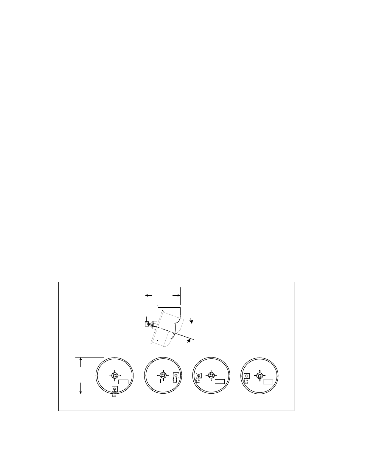
Figure 1 shows a side view of the various sensors with the tilt and swivel limits of the swivel assembly plus the MS connector
location where the interconnect cable attach from the MP01 or BP01 to the sensor.
10.125 in.
(25.7cm)
20o MAX TILT
ANY DIRECTION
10.6 in.
(27cm)
Dia.
300BR or 310BR300BT or 310BT
380
Figure 1 – MS Connector Locations
385
3
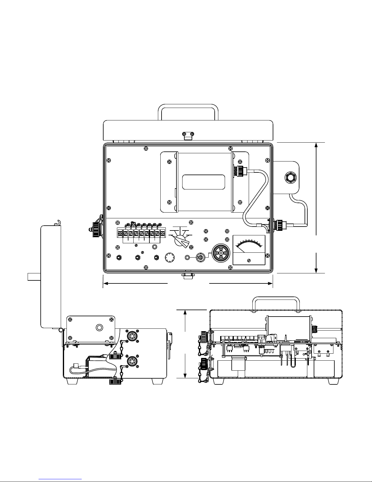
Figure 2 shows the MP01 Monitor Pac. The MP01 connects to the MIL PAC 300BR receiver, MIL PAC 310BR receiver, MIL
PAC 380 transceiver or MIL PAC 385 transceiver with the supplied interconnect cable. It houses a 5 AH battery to power the
sensor and associated electronics, a RF alarm transmitter, a test/alignment meter to assist with setup, audible and visual alarm
indicators, a shielded terminal strip and on/off switches. On the case side is the mount for the two-foot whip antenna. There
are two MS style connectors on the outside of the MP01. One is for connecting to the sensor and the other for connecting to an
optional external DC source such as a power supply, solar panel or larger battery. A mating connector is provided.
WARNING
DO NOT TURN ON RADIO WITHOUT
ANTENNA PROPERLY CONNECTED.
DAMAGE TO RADIO MAY RESULT.
OFF
SOUTHWEST
MICROWAVE
MADE IN USA
MODEL
MP01
AUDIO
0
.4 .6
.2
MILLIAMPERES
.8
1
D.C.
9 inches
(229mm)
N.O. N.C.
12VDC
RADIO-+16VAC
BATTERYPOWER RADIO
COM
ONONOFF OFF ONOFF
CHARGER
FUSE
REG P/S
P/S
ALIGN
OFF
SENS
2A
LIGHT
12 inches
(305mm)
A
EXT 12VDC
TO TRANSCEIVER
NEG
NEG
A
6 inches
(152mm)
4
Figure 2 – MP01 Monitor Pac
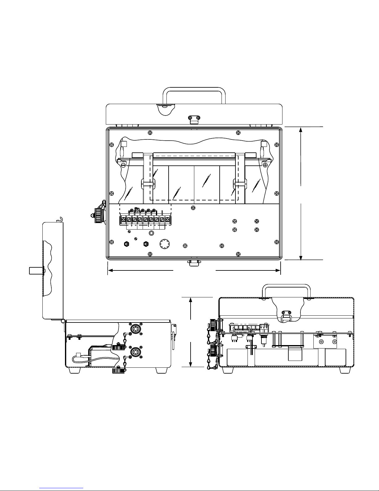
Figure 3 shows the BP01 Battery Pac. The BP01 connects to the MIL PAC 300BT transmitter or MIL PAC 310BT transmitter
with the supplied interconnect cable. It houses a 5 AH battery to power the sensor and associated electronics, a shielded
terminal strip and on/off switches. There are two MS style connectors on the outside of the BP01. One is for connecting to the
sensor and the other for connecting to an optional external DC source such as a power supply, solar panel or larger battery. A
mating connector is provided.
NEG
NEG
POS
POS
9 inches
(229mm)
SOUTHWEST
MICROWAVE
MADE IN USA
12VDC
OFF ON
POWER
+
-
OFF ON
16VAC
CHARGER
BATTERY
SP2SP1TEST
FUSE
1A
MODEL
BP01
12 inches
(305mm)
A
EXT 12 VDC
TO TRANSMITTER
NEG
NEG
A
6 inches
(152mm)
Figure 3 – BP01 Battery PAC
5
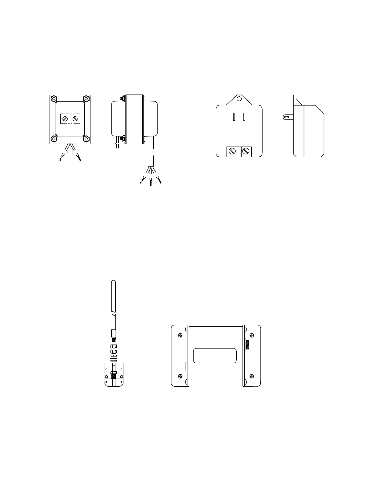
Each Model BP01 and MP01 includes a step-down transformer to charge the internal batteries through the 16.5 VAC
terminals. It can also be used to power the system. Figure 4 shows the Model PT61 220 VAC to 16.5 VAC transformer and the
Model PT62 110 VAC to 16.5 VAC transformer.
PT62PT61
Figure 4 – PT61 and PT62 Transformers
Each MP01 Monitor Pac includes a RF alarm transmitter to transmit the relay closure of the sensor. When activated the
transmitter will send a 10 watt, 27.255 MHz, digital encoded, FSK modulated, signal to its companion receiver. The
transmitter has full supervision capabilities. Two 8-position switches set the units system code to one of 65,536 possibilities. A
two-foot whip antenna is also included. The antenna hardware is mounted to the side of the MP01 as shown in Figure 2. The
maximum range is 1 (one) mile when the MP01 is at ground level. Figure 5 shows the RF alarm transmitter and antenna. Other
optional radios are also available. Please contact the factory.
6
WARNING
DO NOT TURN ON RADIO WITHOUT
ANTENNA PROPERLY CONNECTED.
DAMAGE TO RADIO MAY RESULT.
Figure 5 – RF Alarm Transmitter and Antenna
 Loading...