

Southwest Microwave 380 Users Manual

Southwest Microwave, Inc.
Security Systems Division
TECHNICAL MANUAL
MODEL 380
OUTDOOR MICROWAVE TRANSCEIVER
SOUTHWEST MICROWAVE, INC.
9055 S. McKemy Street
Tempe, Arizona 85284-2946
TEL (480) 783-0201
FAX (480) 783-0401

TABLE OF CONTENTS
INTRODUCTION
OPERATION
THEORY
SPECIFICATIONS
SITE PREPARATION
LOCATION OF TRANSCEIVERS
MULTIPLE UNIT INSTALLATIONS
MOUNTING
POWER WIRING
CONNECTIONS
ALIGNMENT AND TEST
PREVENTATIVE MAINTENANCE
OPTIONAL EQUIPMENT
...............................................................................................................................................................................
.................................................................................................................................................................
.........................................................................................................................................................................
................................................................................................................................................................
..........................................................................................................................................................
......................................................................................................................................
........................................................................................................................................................................
...............................................................................................................................................................
.................................................................................................................................................................
.................................................................................................................................................
.................................................................................................................................................
..............................................................................................................................
................................................................................................................................
3
3
4
7
8
9
11
13
14
15
16
17
18
WARRANTY AND RETURN INFORMATION
NOTE: This manual is for Models 380 and 380-33453 March 2003
..............................................................................................................
18
2
INTRODUCTION_____________________________________________________________
Model 380 Outdoor Microwave Transceiver incorporates state-of-the-art technology and innovative electronic circuitry
to provide reliable detection in the outdoor environment. A unique continuously variable Range Cutoff (RCO) circuit
allows maximum detection range to be established independently of object size, thereby eliminating alarms caused by
large objects beyond the desired detection range. Model 380 is also equipped with Zero Range Suppression (ZRS)
circuitry that reduces sensitivity to small objects very close to the transceiver so that alarms due to rain or vibration are
minimized.
Model 380 includes synchronization and addressing circuitry that enables simultaneous operation of up to 16 units
without mutual interference. The Model 380 is also built with staggered RF frequencies (Channel A and B) to help
minimize mutual interference. Model 380 may be mounted to a variety of posts or wall structures by means of its
universal-mounting bracket. A military style multi-pin connector, at the rear of the transceiver housing, permits remote
monitoring and diagnostics of critical system parameters.
OPERATION_________________________________________________________________
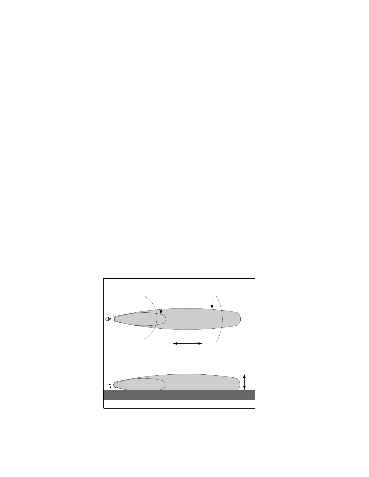
Model 380 includes both transmitter and receiver in a single enclosure. The transmitter radiates microwave energy that
is reflected back into the receiver by objects within the detection zone. The observed detection zone is established by
two controls - Sensitivity and Range. Figure 1A shows the zone of detection (horizontal pattern) for an upright man
when Model 380 is mounted 2.5 feet (.75 meters) above smooth earth with its beam oriented parallel to the ground. The
Range control adjusts the maximum range of the system and the Sensitivity control primarily adjusts the width. Figure
1B shows the vertical pattern for the same configuration, note that the detection zone does not extend into the small area
immediately under Model 380.
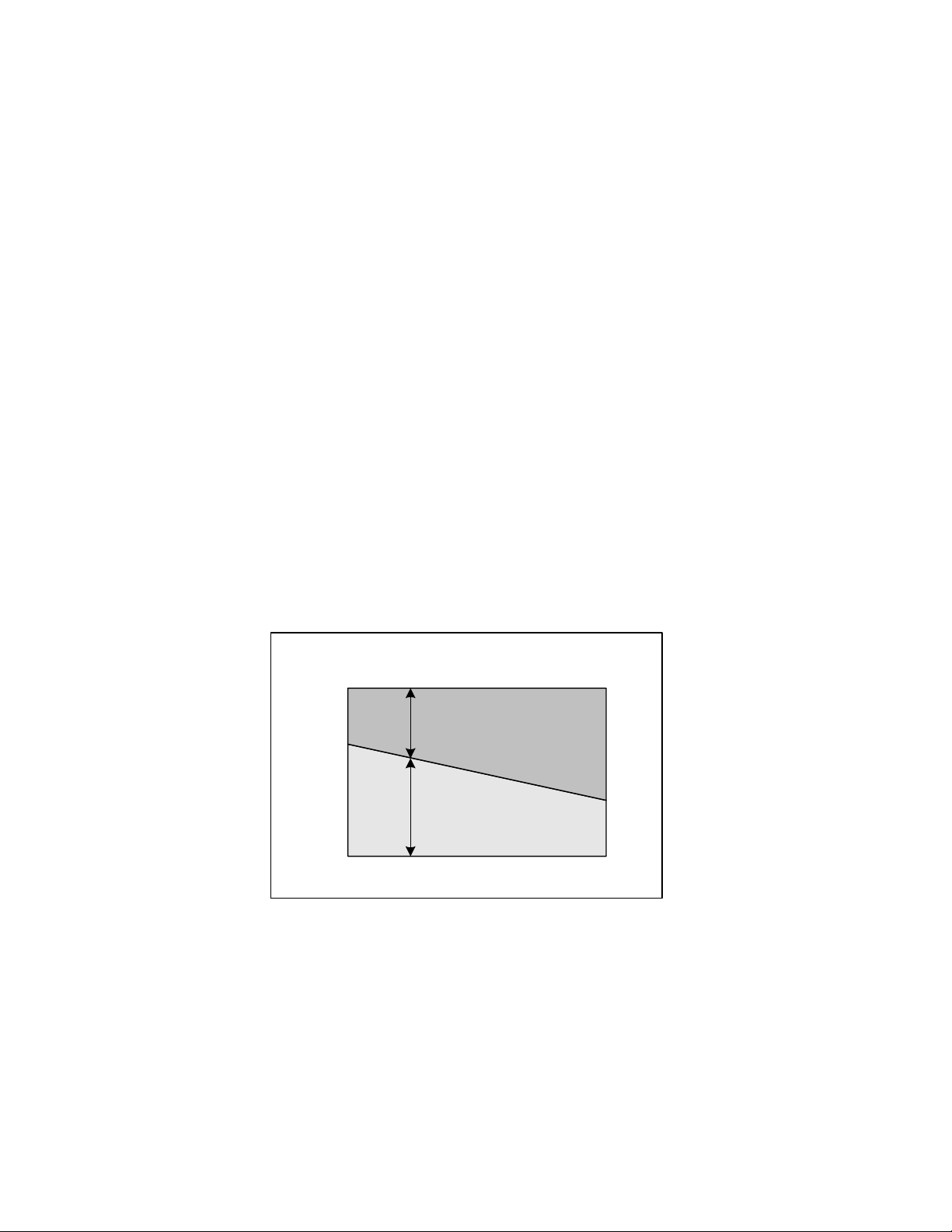
This area varies with the Sensitivity setting as shown in Figure 2. In order to provide uninterrupted detection of a man
walking or crawling on his hands and knees, an additional unit must provide overlap protection such as shown in Figure
3. Detection of a man crawling "commando-style" may require additional overlap or special site preparation.
Sensitivity should always be adjusted to the absolute lowest setting that will meet site security requirements. Excessively
high sensitivity may cause nuisance alarms from high grass, small birds or windblown debris in the detection zone.
Model 380 responds to any motion within the detection zone.
A) HORIZONTAL PATTERN
SENSITIVITY MAXIMUM
SENSITIVITY MINIMUM
50' MIN
(15m)
ACTIVE
DETECTION
PATTERN
RCO
CONTINUOUSLY
VARIABLE
CUTOFF
200' MAX
(122m)
PATTERN
HEIGHT
15' MAX
(3.4m)
B) VERTICAL PATTERN
Figure 1 - Model 380 Detection Pattern
3
THEORY_____________________________________________________________________
A microwave transceiver transmits microwave energy into the detection zone, and objects in the zone reflect energy
back to its receiver. Whenever an object is moving, the Doppler effect shifts the frequency of its reflection and the
transceiver generates an alarm whenever it detects a frequency shift in the reflected energy. The size of a frequencyshifted reflection that will cause alarms is varied by the Sensitivity control causing the detection zone for any particular
object to vary as shown in Figure 1. Note that Figure 1 applies to an upright walking man. The detection zone for a
large object such as a truck would be larger and for a small object such as a man, crawling would be smaller.
In Model 380, the transmitter is periodically turned on and off, but the receiver is turned on only for a short period after
the transmitter is turned on. Because microwave energy always travels at nearly the speed of light, elapsed time between
transmission and reception provides an accurate measurement of range (distance) from Model 380 to whatever object is
being illuminated. By turning the receiver on only during the period corresponding to maximum desired range,
reflections from objects beyond this range are ignored, even if the reflections are very large. In Model 380, the range
control determines the time that the receiver observes the reflections and thus sets the maximum (RCO) distance as
shown in Figure 1.
Reflections from small objects such as raindrops very near the transceiver are frequently as large as reflections from a
man in the detection zone. Model 380 overcomes this problem by transmitting two different microwave frequencies on
alternate transmitter pulses. Because each object reflects two different frequencies, the receiver can determine the
distance to each object. At zero range (in the vicinity of the radome), the phase difference between the two frequencies
is approximately zero. By combining the two Doppler signals in a difference amplifier, the gain is reduced significantly.
In order to insure a continuous perimeter, it is necessary to provide sufficient overlap so that the dead zone immediately
below and behind the sensor is protected. Figures 2 and 3 show required overlap information.
DEAD ZONE
50' (15.2m)
40' (12.2m)
30' (9.1m)
20' (6.1m)
10' (3.0m)
5' (1.5m)
0'
MIN
Figure 2 - Required Overlap vs. Sensitivity
REQUIRED OVERLAP
(2.5 foot (0.8m) mounting height)
MAXIMUM SECURITY
MINIMUM SECURITY
SENSITIVITY
1/2
MAX
4
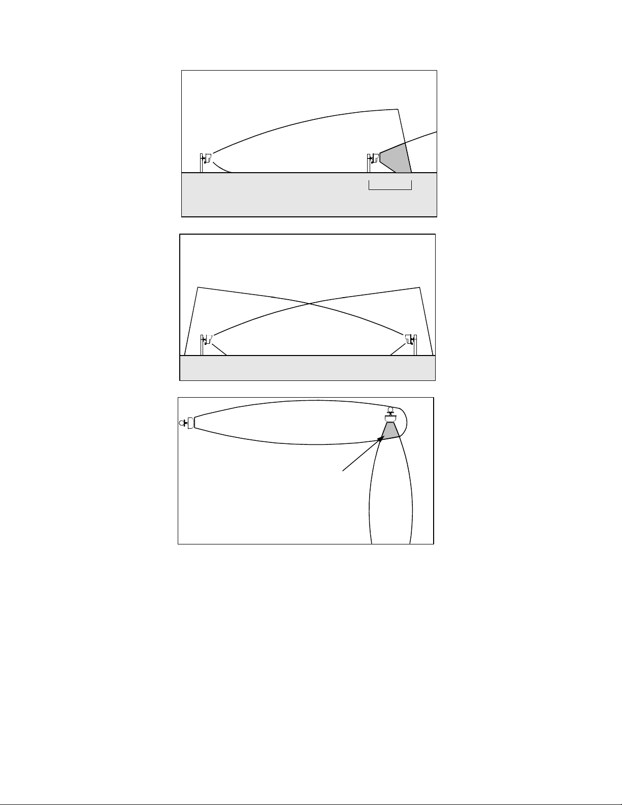
Overlap Area
OVERLAP AREA
Figure 3 - Overlap of Model 380 Detection Zone
Figure 4 shows a block diagram of Model 380. Logic pulses generated by the synchronization phase-locked loop (PLL)
and the associated counter and 4-bit comparator provide the command for turning the transmitter on and off at a
prescribed rate, and at one of 16 unique periods of time or addresses. A signal is also derived for switching the
transmitter alternately between the two frequencies required for Zero Range Suppression.
The Range control sets the delay generated logic functions initiated by the turn on of the transmitter.
The transmitter is a cavity stabilized fundamental GUNN oscillator that provides 32 milliwatts (peak) of microwave
power. Most of the oscillator power is transmitted into space by the parabolic antenna, but a small portion is mixed with
the reflected signal and is coupled to a microwave detector within the antenna assembly. The detector is a Schottky
diode that extracts the Doppler shift frequency from the reflected microwave energy.
5
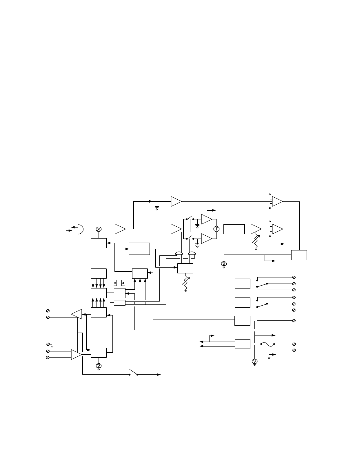
The Doppler signal is amplified and then gated to one of two sample and hold amplifiers. The amplifiers are selected by
means of S1 and S2 and are switched coincident with the alternate transmitter frequencies. SI and S2 are held closed for
a period of time determined by the range cut-off circuit. Range gating is accomplished by turning on the switch at the
same time the transmitter is activated. The switch is then opened at a time selected by the range cut-off circuit so that the
information entering the receiver due to targets outside the range cut-off are not processed. The sampling capacitors
following the switches hold their charge when the switches are opened. This provides a means for reconstructing each
signal after it is sampled.
At the differential amplifier input, the phase between channels is a function of distance to the target and separation of the
two transmitter frequencies. Signals arriving from RCO distance are out of phase while signals from zero distance are in
phase. Thus, amplifier output is large for signals from RCO distance and small for signals from zero distance.
The differential amplifier output is amplified by a factor established by the Sensitivity control and compared with
positive and negative voltage thresholds. Whenever the signal exceeds plus or minus one volt, a pulse is delivered to an
integrator. After a predetermined number of pulses have been stored, the integrator output voltage exceeds alarm
threshold and the alarm relay is de-energized for two seconds.
A test function is included in Model 380. When gated on by a +5 to +12 VDC command (at the terminal block), the test
function provides a phantom signal into the transmitter and receiver circuits to generate an alarm and test the entire 380
detection system.
VH
TB1-10
+
TB1-11
-
+
-
TB1-12
TB1-13
TB1-14
+
Fc Fd
-
MASTER
OUTPUT
SLAVE
INPUT
Fc
TX
OSC
ADDR
4 BIT
COMP
CTR
PLL
LOCK
LED
1.0 uSec
ONE
SHOT
+2
LEADING
EDGE
DETECTOR
VCO
DRIVER
SYNC
ON OFF
+5V
RCO
TIMING
S1
S2
FbFa
RANGE
+7V
+9V
+5V
AMP
AMP
P1-C
+
LOW-PASS
-
FILTER
SENS
ALARM
LED
ALARM
RELAY
TAMPER
SWITCH
VCO
SUPPLY
P1-B
POWER
SUPPLY
POWER
LED
VL
THRESHOLD
VH
VL
P1-F
TB1-6
TB1-7
TB1-8
TB1-3
TB1-4
TB1-5
TB1-9
P1-A
TB1-1
TB1-2
P1-D
P1-E
ALARM
+
-
CKTS
N.O.
COM
N.C.
N.O.
COM
N.C.
TEST
Figure 4 - Block Diagram Model 380
6
 Loading...