

Southwest Microwave 330 Users Manual

Southwest Microwave, In c.
Security Systems Division
INTREPID™
MicroWave 330
A DIGITAL MICOWAVE
OUTDOOR PERIMETER INTRUSION DETECTION SYSTEM
MicroWave 330 Installa tion
and Operation Manual
Version 0

Trademark Notice and Certifications
INTREPID™, MicroPoint™ and MicroTrack™ are registered trademarks of Southwest Microwave, Inc.
Copyright 1995 and 2012 Southwest Microwave, Inc. All rights Reserved.
FCC Notice
MicroWave 330 is classified as a field disturbance sensor.
This device complies with FCC Rules Part 15.245. Operation is subject to the following two conditions:
This device may not cause harmful interference and this device must accept interference received, including
interference that may cause undesired operation.
Notice: changes or modifications not expressly approved by Southwest Microwave, Inc. could void the
user’s authority to operate the equipment.
This equipment has been tested and found to comply with the limits for a Class A digital device, pursuant to
part 15 of the FCC Rules. These limits are designed to provide reasonable protection against harmful
interference when the equipment is operated in a commercial environment. This equipment generates, uses,
and can radiate radio frequency energy and, if not installed and used in accordance with the instruction
manual, may cause harmful interference to radio communications. Operation of this equipment in a
residential area is likely to cause harmful interference in which case the user will be required to correct the
interference at his own expense.
RoHS Compliant
Radiation Safety
The allowable standard minimum of safe radiation exposure level in the United States as established by the
American National Standards Institute is 10mW/cm
1mW/cm
approximately.0186mW/cm
2
. The average Southwest Microwave sensor surface radiation level (when in operation) is
2
or 1/50 of the proposed lower standard. This level rapidly dissipates at
distances from the unit. For example, at one meter, the figure reduces to .0012mW/cm
proposed level.
Copyright Southwest Microwave, Inc. May 2012
Southwest Microwave, Inc.
9055 South McKemy Street
Tempe, Arizona 85284-2946
Tel: (480) 783-0201
Fax: (480) 783-0401
Email: infossd@southwestmicrowave.com
Web: www.southwestmicrowave.com
2
. There is currently a proposal to drop this limit to
2
or 1/800 of the
2 Version 0

INTREPID™ MicroWave 330 S oftware
Southwest Microwave, Inc. thanks you for your purchase of the INTREPID MicroWave 330 Digital Microwave
Intrusion Link. Please refer to the Universal Installation Service Tool II (UIST II) for the software setup of this
sensor.
One disk is required to setup the system. It is called:
Universal Installation Service Tool II (UIST II)
This software is used to configure and set-up the system as well as being used for maintenance and
troubleshooting the system.
Software provided by Southwest Microwave, Inc. is subject to the license agreement terms of the individual
product. A copy of the license agreement is available by contacting Southwest Microwave, Inc.
3 Version 0

Table of Contents
1. Introduction ................................................................................................................................................ 5
2. Hardware .................................................................................................................................................... 5
2.1 MicroWave 330 Link ............................................................................................................................ 5
2.2 Optional Power Supplies ...................................................................................................................... 6
2.3 Oprional Accessories ............................................................................................................................ 6
3. Principles of Operation and Detection ..................................................................................................... 6
3.1 Description ............................................................................................................................................ 6
3.2 Range of Operation ............................................................................................................................... 7
3.3 Overlaps ................................................................................................................................................ 8
3.3.1 High Security Overlaps ................................................................................................................... 9
3.4 Transmitter Block Diagram .................................................................................................................. 9
3.5 Receiver Block Diagram ..................................................................................................................... 10
3.6 Specifications ...................................................................................................................................... 11
4. Installation Instructions .......................................................................................................................... 13
4.1 Location of MicroWave 330 ............................................................................................................... 13
4.1.1 Required Area ................................................................................................................................ 13
4.1.2 Terrain ........................................................................................................................................... 14
4.1.2.1 Terrain in High Security Applications .................................................................................... 14
4.1.3 Physical Protection ........................................................................................................................ 15
4.1.4 Best Security .................................................................................................................................. 15
4.2 Mounting of MicroWave 330 ............................................................................................................. 16
5. Modes of Operation ................................................................................................................................. 18
5.1 Free Running Mode ............................................................................................................................ 18
5.2 Tethered Mode .................................................................................................................................... 19
6. Wiring ....................................................................................................................................................... 20
6.1 Power Supply Wiring ......................................................................................................................... 20
6.2 Communications Wiring ..................................................................................................................... 21
6.3 Tethered Wiring .................................................................................................................................. 21
6.4 Synchronized Wiring .......................................................................................................................... 22
6.5 Remote Test ........................................................................................................................................ 23
7. Terminals, Switches and Indicators ....................................................................................................... 24
7.1 MicroWave 330T Transmitter ............................................................................................................ 24
7.1.1 Channel Select Switch ................................................................................................................... 24
7.1.2 External / Internal Modu la tion Switch ................................................................................... ....... 24
7.2 MicroWave 330R Receiver ................................................................................................................ 25
7.2.1 Address Switch .............................................................................................................................. 26
7.1.2 Audio Alarm Switch ...................................................................................................................... 26
7.2.3 Communications Ports ................................................................................................................... 26
8. Connecting the Transmitter and Receiver ............................................................................................. 26
8.1 MicroWave 330T Transmitter Connections ....................................................................................... 26
8.2 MicroWave 330R Receiver Connections ........................................................................................... 27
9. Alignment and Testing ............................................................................................................................ 27
10. Preventive Maintenance .......................................................................................................................... 28
11. Limited Warranty .................................................................................................................................... 29
12. Returning Equipment under Warranty ........................................................................................
13. Returning Equipment fro Non-Warranty Repair ................................................................................. 30
14. Replacement Parts ................................................................................................................................... 30
......... 29
4 Version 0
1.0 Introduction
The MicroWave 330 is part of the INTREPID™ Series II family of products. It is digital microwave field
disturbance sensor providing perimeter protection for open areas, gates, entryway, walls and rooftop
applications. It provides volumetric detection of human intruders with minimal environmental nuisance alarms.
Advanced digital signal processing (DSP) allows continuous monitoring of intrusion alarm and tamper switch
status, received signal strength for path fault and detection parameters. A system controller such as the Relay
Control Module II (RCM II), Control Module II (CM II), Graphic Control Module II (GCM II), Perimeter
Security Manager (PSM) or SDK (Software Development Kit) is required to poll and configure alarm sources
from MicroWave 330 for annunciation.
MicroWave 330 operates at K-band (24.125 GHz) frequency, achieving superior performance to X-band
sensors. Because K-band is 2.5 times higher the X-band, the multipath signal generated by an intruder is more
focused, and detection of slow-moving intruders is correspondingly better. At K-band frequency, the unit also
has low susceptibility to outside interference from air/seaport radar or other microwave systems.
MicroWave 330 communicates with other INTREPID Series II devices using RS422 communications. This
communication can be done over 22 or 24 gauge stranded shielded twisted pair wire (max 5,000 feet [1,500m]
between devices) or with fiber optic devices. The address of each MicroWave 330 is set by a dip switch on the
receiver circuit board.
MicroWave 330 operates from 10.5 to 60 VDC @ 2.5 Watts with a minimum startup current of 250mA. The
operating currents with standard power supplies are: 12 VDC @ 125mA (Tx) / 208mA (Rx), 24 VDC @ 63mA
(Tx) / 104mA (Rx) and 48 VDC @ 32mA (Tx) / 52mA (Rx).
2.0 Hardware
2.1 MicroWave 330 Digital Microwave Link
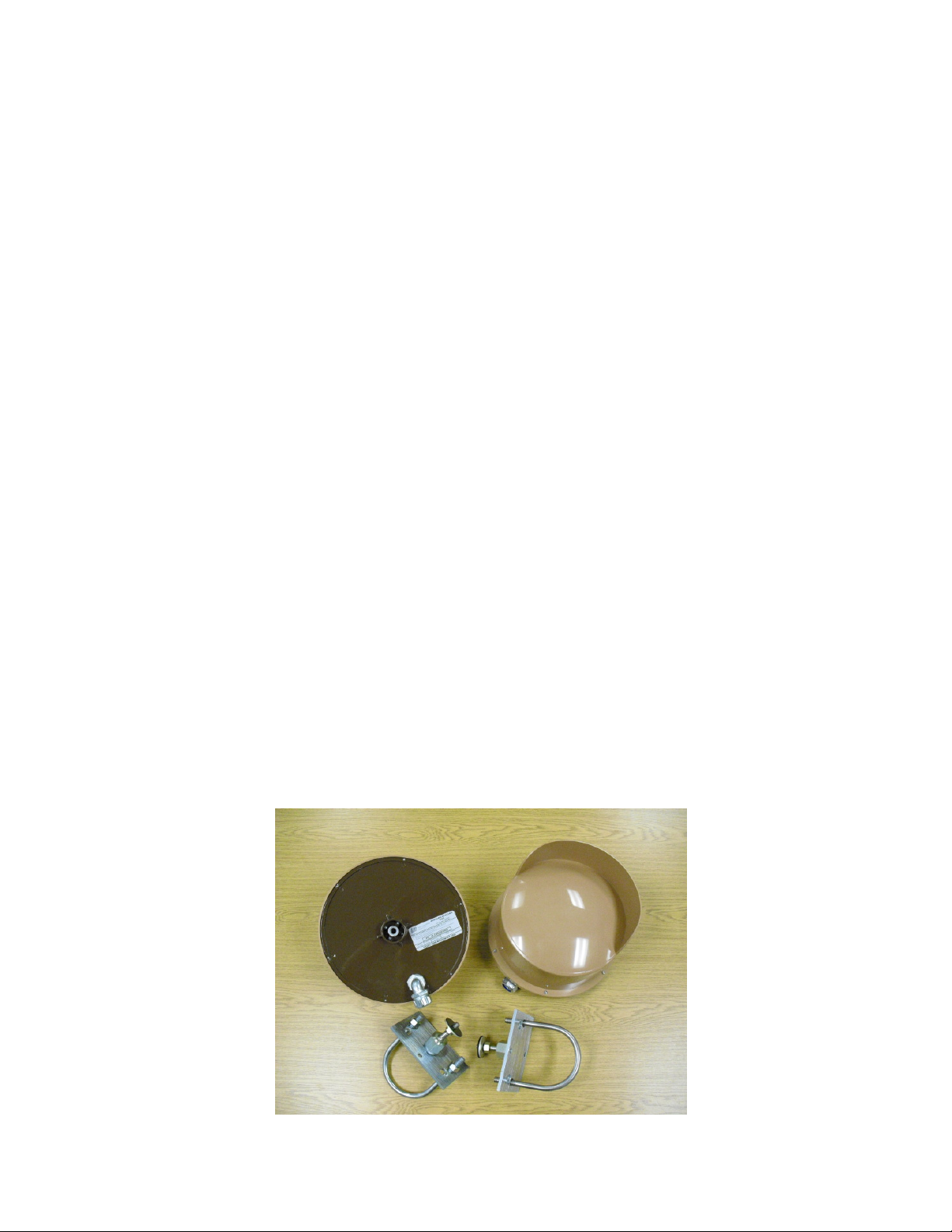
Each MicroWave 330 Digital Microwave Link includes a MicroWave 330 Transmitter, Microwave 330
Receiver and two MB62 Universal Mounting Brackets as shown in Figure 1.
MicroWave 330 dimensions are 10.6 in diameter (270mm) and 10.125 in (257mm) front to back (from radome
face to mounting bracket). Each unit weighs 4.5 lbs (2.041kg).
Figure 1 – MicroWave 330 Hardware
5 Version 0

2.2 Optional Power Su pplies
12 VDC power supply: Model PS13 Power Supply operates from 85-246VAC, 47-63Hz and furnishes 13.6
VDC at up to 2.8A. Power supplies contain automatic switchover and battery charging circuitry for optional
standby batteries of up to 25AH. Temperature rated from 14° to 122° F (-10° to 50° C). UL, ETS, EMC, CE,
RoHS compliant.
12 VDC power supplies: Model PS40 Power Supply operates from 120 VAC, 50-60Hz, 0.5A and furnishes
13.7 VDC at up to 1.6A. Model PS41 Power Supply operates from 220 VAC, 50-60Hz, 0.25A. Both contain
automatic switchover and battery charging circuitry for optional standby batteries of up to 25AH and are fused
on both input and output for maximum protection. Temperature rated from -40° to 150° F (-40° to 66° C).
24 VDC power supply: Model 78B1064 operates from 120VAC to provide 24VDC at 5A with 6.5AH battery
backup. Includes; indoor enclosure 15 x 11 x 4 in. (381 x 280 x 102mm). Temperature rated from 32° to 122° F
(0° to 50° C).
48 VDC power supplies: Model PS48 operates from 120VAC to provide 48VDC at 3A. Includes; indoor
enclosure 14 x 12 x 4 in. (356 x 305 x 102mm). Model PS49 operates from 220VAC to provide 48VDC at 3A.
This supply does not include enclosure. Temperature rated from 32° to 122° F (0° to 50° C).
from 32° to 122° F (0° to 50° C). UL, CSA, TUV, CE compliant.
Temperature rated
2.3 Optional Accessories
MB65 Mounting Bracket: Model MB65 is a heavy duty, position locking non corrosive mounting bracket for a
4 inch (102mm) O.D. post.
RS14 Radome: Model RS14 is a shielded radome used to add additional RFI/EMI protection for Microwave
330 transmitter or receiver.
48C15529-A01 Enhanced Reflector: Model 48C15529-A01 is an optional reflector to provide a shorter “dead
zone” to MicroWave 330 transmitter and receiver. This option reduces maximum range to 400 feet (122m).
02A15483-A01 Radome Latch Kit: Model 02A15483-A01 replaces the 6 radome screws for quicker access to
the sensor electronics. Two kits are required for each MicroWave 330 Digital MicroWave Link.
JB70A: Lightning/Surge Protection module protects the data communications and power lines. Includes;
enclosure with terminal strips for wire connections.
3.0 Principles of Operation and Detection
3.1 Description
The MicroWave 330 Transmitter radiates amplitude modulated K-band energy that travels to the MicroWave
330 Receiver where it is detected. A microprocessor and proprietary algorithms provide powerful Digital Signal
Processing to recognize the unique bi-static digital signatures of intruders walking, jumping, running or crawling
through the detection field. Targets are classified and scored in real time at each sensor and stored in the
receiver’s flash memory. When an intruder approaches the beam the energy at the receiver changes in signal
amplitude directly related to the targets size and density allowing the sensor to discriminate between targets.
MicroWave 330 will alarm on average sized humans walking, running or crawling on hands and knees through
the detection pattern. Field adjustments can provide alarm on larger or smaller targets, depending on the specific
site requirements. Operation of MicroWave 330 is illustrated in Figure 2.
6 Version 0
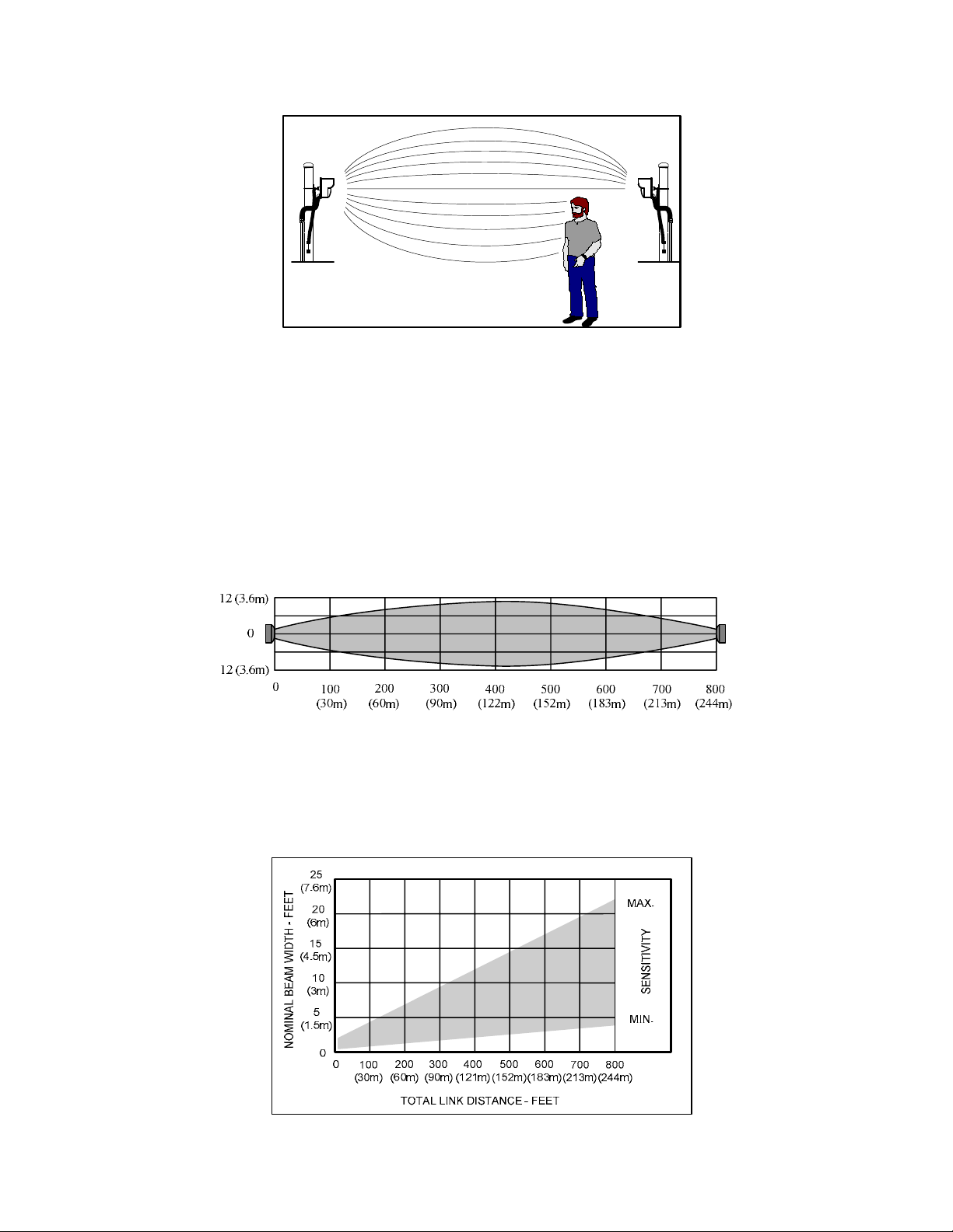
Figure 2 – Operation of MicroWave 330 Link
3.2 Range of Operation
A single MicroWave 330 may cover a distance of 800 feet (244m). The receiver is equipped with automatic gain
control (AGC), which automatically adjusts receiver for the distance to be covered and sets the Path Fault
parameter.
Typical maximum width protection pattern of MicroWave 330 is shown in Figure 3 for mounting height of 2.5
feet (.76m) above smooth earth.
maximum and Receiver “Sensitivity” control is set to maximum
Figure 4 illustrates how pattern width varies with Transmitter-Receiver distance and sensitivity setting. Actual
patterns will vary somewhat with site topography and surface condition. Generally, lower mounting height or
rougher surface will increase pattern width. For example, if the total link distance is 500 feet (152.4m) and the
sensitivity adjustment set to mid-point, Figure 4 indicates the detection pattern width to be 7.5 feet (2.3m).
Maximum width will be when Transmitter-Receiver distance is at
Figure 3 – Typical Maximum Horizontal Pattern
Figure 4 – Typical Maximum Horizontal Pattern
7 Version 0
Vertical protection pattern will also depend upon Transmitter-Receiver distance, mounting height and
“Sensitivity” setting. Actual patterns will vary somewhat with site topography and surface condition. Typical
pattern height is 50 to 75% of pattern width. Approximate vertical protection pattern is shown in Figure 5. For
example, at 50 feet (15m) with minimum sensitivity the pattern height is 5 feet (1.5m).
25
(7.6m)
20
(6m)
350
MAX.
MIN.
400
(121m)
SENSITIVITY
15
(4.5m)
10
(3m)
5
(1.5m)
NOMINAL BEAM HEIGHT - FEET
0
0
50
(15m)
100
(30m)
(45m)
150
200
250
(60m)
(76m)
DISTANCE - FEET
300
(90m)
(107m)
Figure 5 – Typical Vertical Pattern
3.3 Overlaps
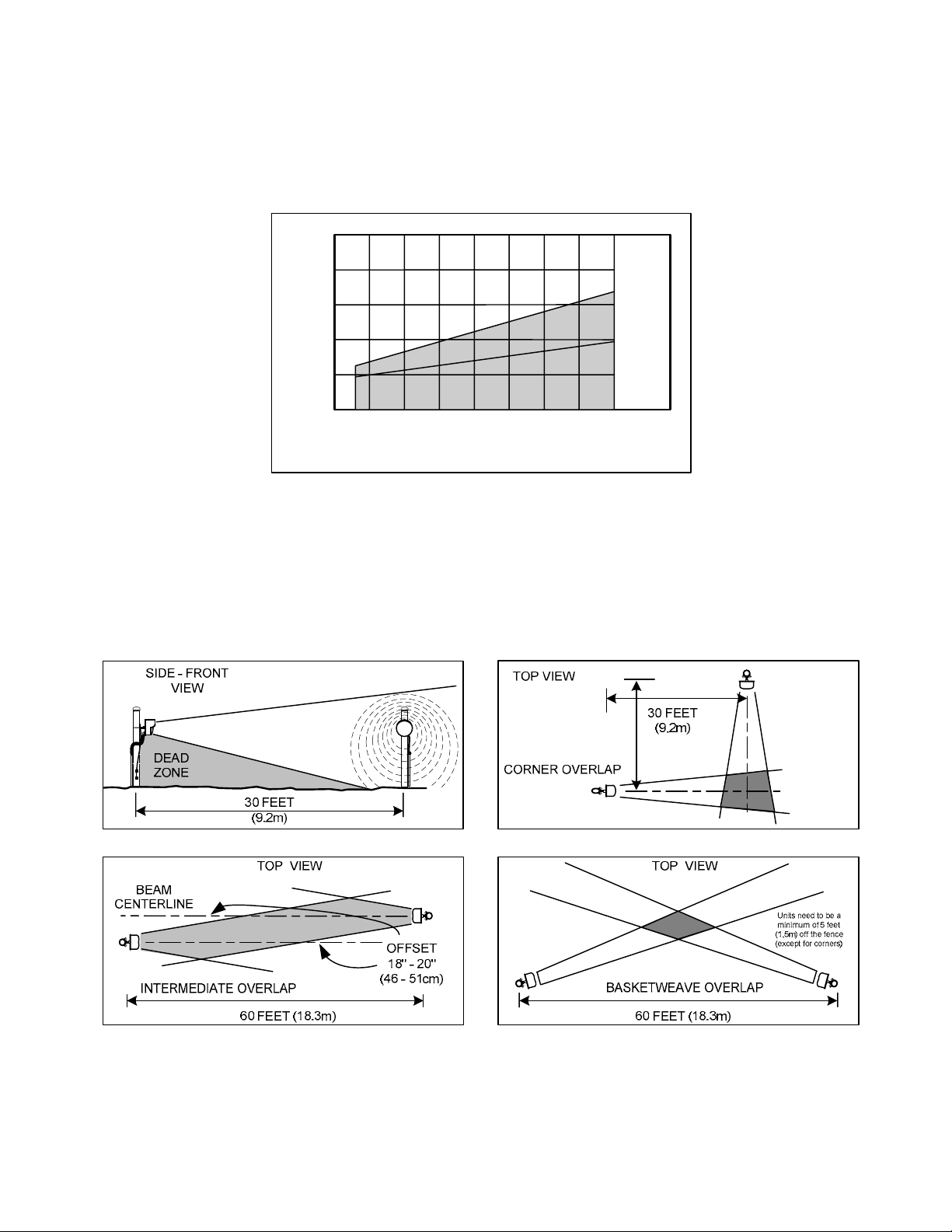
Protection pattern below centerline will tend to fill area between beam centerline and ground except for a “dead
zone” immediately in front of and below Transmitter and Receiver. This zone is best protected by overlapping
links at ends and corners as shown in Figures 6.
Figure 6 – Overlaps and Dead Zone
Corner overlaps should be 30 feet (9.2m) minimum. Intermediate or in line overlaps should be 60 feet (18.3m)
minimum with a beam centerline offset of 18 to 20 inches (46-51cm). Basket weave overlaps should be 60 feet
(18.3m) minimum and a minimum of 5 feet (1.5m) off the fence (except for corners).
8 Version 0
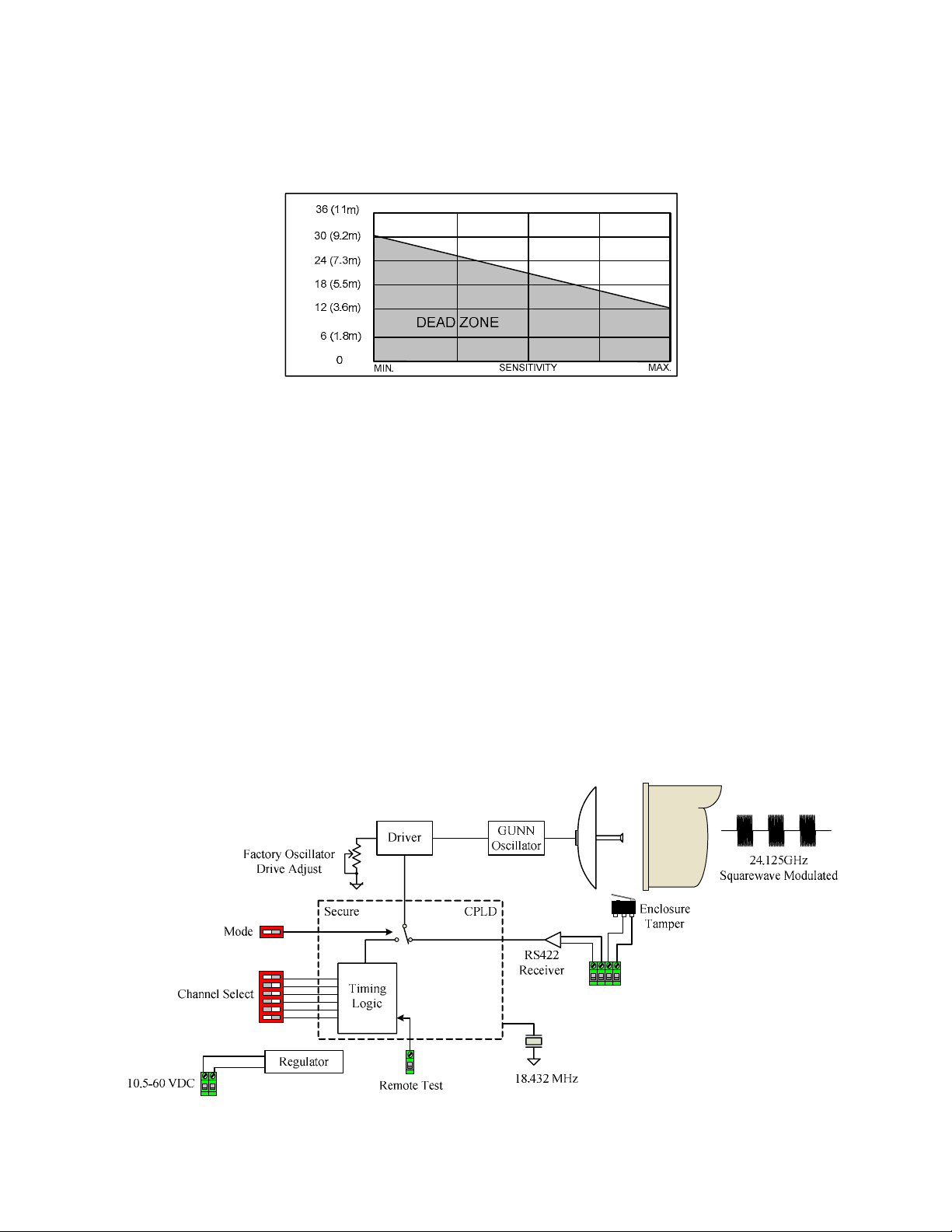
Figure 7 shows amount of overlap required to detect against hands and knees crawling intruders, as a function of
“Sensitivity” setting. It is always recommended to keep the sensitivity setting at the lowest possible value to
minimize nuisance alarms but maintaining a high probability of detection.
DEAD ZONE - FEET
Figure 7 – Sensitivity vs Dead Zone
3.3.1 High Security Overlaps
For maximum-security applications where detection of prone “commando style” crawl is required, the
intermediate over-lap should be 60 feet (18.3m) minimum with parallel beam centerline offset of 18 inches
(46cm) maximum. The corner overlaps should be 30 feet (9.2m) minimum. Terrain flatness should be no more
than plus three inches or minus three inches deviation from a plane drawn between the transmitter and receiver.
The zone length (Transmitter to Receiver) should not exceed 400 feet (122m).
High security applications also use stacked link configurations to meet site requirements. A stacked link may
consist of two or more MicroWave 330 links or used in combination with the Model 300B link which operates
at X-band frequency of 10.525 GHz. A stacked link greatly reduces the dead zone and increases PD.
3.4 Transmitter Block Diagram
MicroWave 330T Transmitter consists of two major subassemblies – RF Assembly and Transmitter Circuit
Board. A block diagram is shown in Figure 8.
Slave
Tamper
Modulation
Figure 8 – MicroWave 330 Transmitter
9 Version 0
The RF assembly consists of a Gunn oscillator, which generates K-band microwave energy and the parabolic
antenna system. The Transmitter circuit board contains voltage regulator and modulation circuit to drive the
microwave oscillator and a secure CPLD. Modulation frequency in Free Run Mode is selected from one of six
channels (A, B, C, D, E, and F) by a dip switch on the Transmitter Circuit Board.
The CPLD is responsible for the generation of the asynchronous modulation frequencies when the “Mode”
switch is set to “Internal” position and also for determining the quality of the signal provided on the tether when
the “Mode” switch is set to “External” position.
A “Test” terminal is provided on the Transmitter Circuit Board. Application of 5.0 to 14.0 VDC will cause
Transmitter to turn off and illuminate the red “Channel Error” LED, generating a test alarm at receiver. A green
LED on Transmitter Circuit Board indicates that power is on.
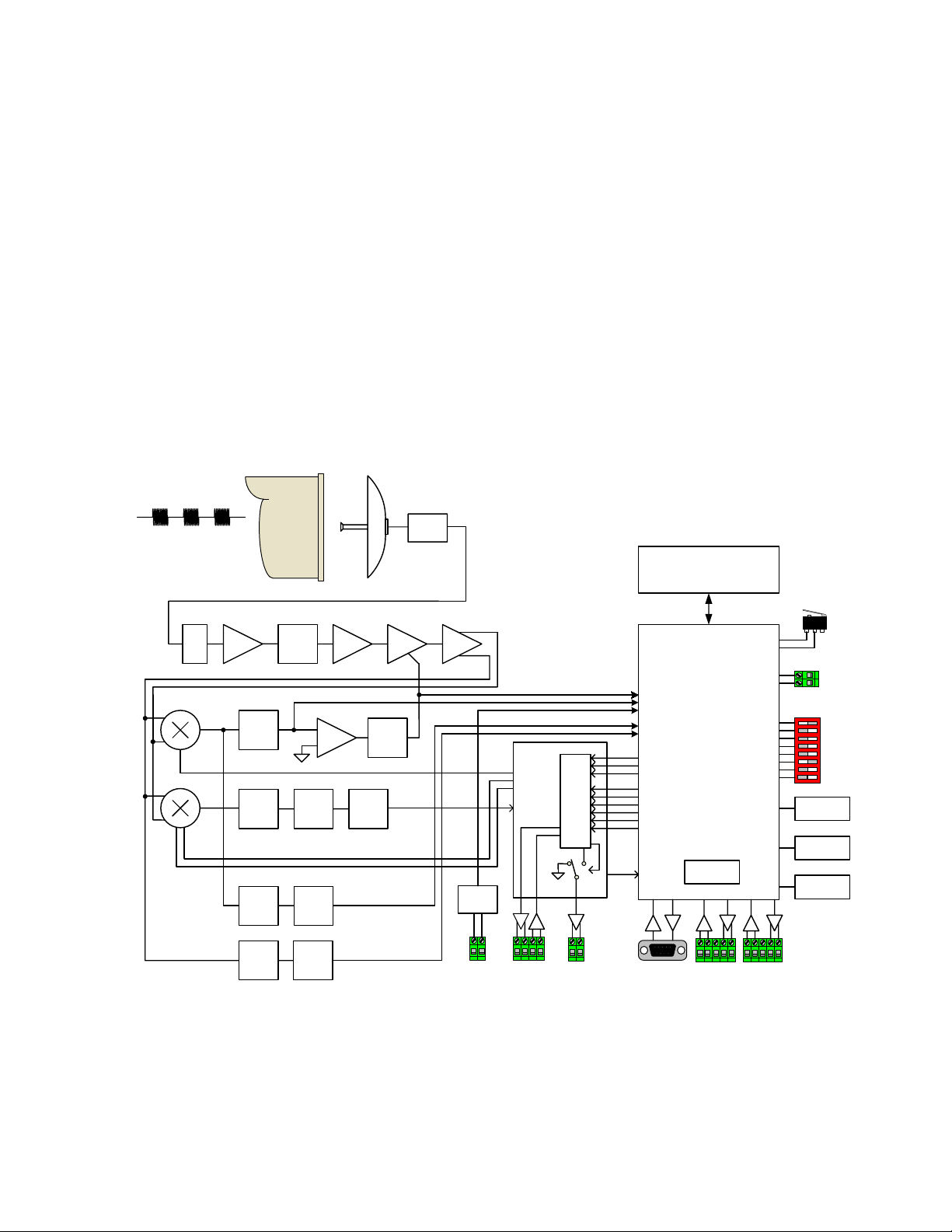
3.5 Receiver Block Diagram
MicroWave 330R Receiver consists of two major subassemblies – RF Assembly and Receiver Circuit Board. A
block diagram is shown in Figure 9.
Cavity
Det.
24.125Ghz
Squarewave Modulated
Low Noise
Bias
30dB
+
-
+
5
LPF
1
LPF
HPF
HPF
BPF
~
~
~
th
st
Level
Shift
Jam
Wrong
Channel
+
-
18.432 MHz
VCXO
AGC
+
-
∫
Secure
CPLD
TX +
TX -
Sync
RX -
RX +
Logic
Timing
TX +
TX -
Channel
Modulation
CLK
(Q)
(I)
Power
Supply
10.5-60VDC
Figure 9 – MicroWave 330 Receiver
CLK
Secu re
Align (ADC)
Target (ADC)
PS (ADC)
RS232
Configuration
Port
Memory
(optional)
CPU
Watchdog
TX +
TX -
Com 1
RS422
Alarm
Network
Enclosure
Tamper
External
Tamper
HI
LO
Node Address
BDM
Reset
RTC
TX +
TX -
Gnd
RX -
RX +
Gnd
Com 2
RS422
Alarm
Network
RX -
RX +
10 Version 0
 Loading...