

Southwestern Bell FM2575 User Manual
STOP-DON'T TAKE ME BACK TO THE STORE.
LOOK-FOR THE TOLL-FREE "HELP" TELEPHONE NUMBER.
LISTEN-AS THE EXPERTS TALK YOU THROUGH THE PROBLEM.
For immediate answers to your questions regarding operation,
missing parts or installation, call the
SOUTHWESTERN BELL FREEDOM PHONE®
Retail Sales Help Line at:
1-800-366-0937
Monday - Friday 8:30 a.m. - 9:00 p.m. EST
Saturday 8:30 a.m. - 12:30 p.m. EST
http: // www. swbfreedomphone. com
Southwestern Bell
®
Integrated Speakerphone Telephone with
Caller ID/Call Waiting and Digital Answering System
Southwestern Bell
Freedom Phone
PLAY
P
L
A
STOP TIME SET/REPEAT
ERASE
ANSWER ON/OFF
ERASE
M1 M2
1
GHI
4
PQRS
7
*
MEMORY
MUTE
call
waiting
SKIP/MEMO
GREETING
Caller ID
CALL BACK
ABC
2
JKL
5
TUV
8
OPER
0
STORE
SPEAKER
D I G I T A L
ANSWERING SYSTEM
Y
REDIAL/PAUSE
WXYZ
FLASH
M3
DEF
3
MNO
6
9
#
NEW CALL
R
E
V
I
E
W
SOUTHWESTERN BELL FREEDOM PHONE®
7475 N. GLEN HARBOR BLVD., GLENDALE, AZ 85307
FM2575 IB-3528A Printed in China
TOLL FREE HELP LINE
1-800-366-0937
http: // www. swbfreedomphone. com
FM2575 OWNER'S MANUAL
Southwestern Bell Freedom Phone FM2575
R
Integrated Speakerphone Telephone with
Caller ID/Call Waiting and Digital Answering System
Contents
Subject Page Subject Page
Location of Controls..............................3
Important Safety Instructions................6
General Information..............................8
Unpacking
Helpful Tips from Customer Service....8
Installation Instructions.........................8
Battery Installation
Desk or Table Installation
Wall Mounting
Setting Up Your FM2575....................11
To Set Language
To Set LCD Display Contrast
To Set Area Code
Telephone Operation...........................12
Tone/Pulse Switch
Dialing a Call
Receiving a Call
Telephone Features..............................13
Ringer Off/Low/High Control
Last Number Redial
Pulse/Tone Combination Dialing
Pause
Hearing Aid Compatibility
Flash
Lighted Keypad
Mute
Call Timer
Memory Dialing..................................14
To Program Priority Numbers
To Program Frequently Called Numbers
To Dial Priority Numbers
To Dial Frequently Called Numbers
To Erase a Stored Number
Answering System Operation.............15
To Turn System On
To Turn System Off
Recording Outgoing Greeting
Checking Your Outgoing Greeting
Setting the Voice Time/Day Stamp
Day Set
Hour Set
Minute Set
AM/PM Set
To Record a Memo
Ring Select
Toll Saver
Voice Activated Recording (VOX)
Message Playback...................................18
Incoming Message
Message Playback
Stop
Repeat
Playback Previous Message
Skip
Erase
Message Full Detection
Call Interrupt
Call Screening
Battery Backup
Remote Operation...................................20
Caller ID Features...................................21
Receiving Call Waiting Caller ID
Reviewing Calls
Caller ID Redial
Caller ID Erase
Priority Calls
LCD Description.....................................24
Answers To Commonly Asked
Questions.................................................25
Trouble Shooting Guide..........................27
FCC Wants You to Know........................30
Service.....................................................31
Limited Warranty....................................32
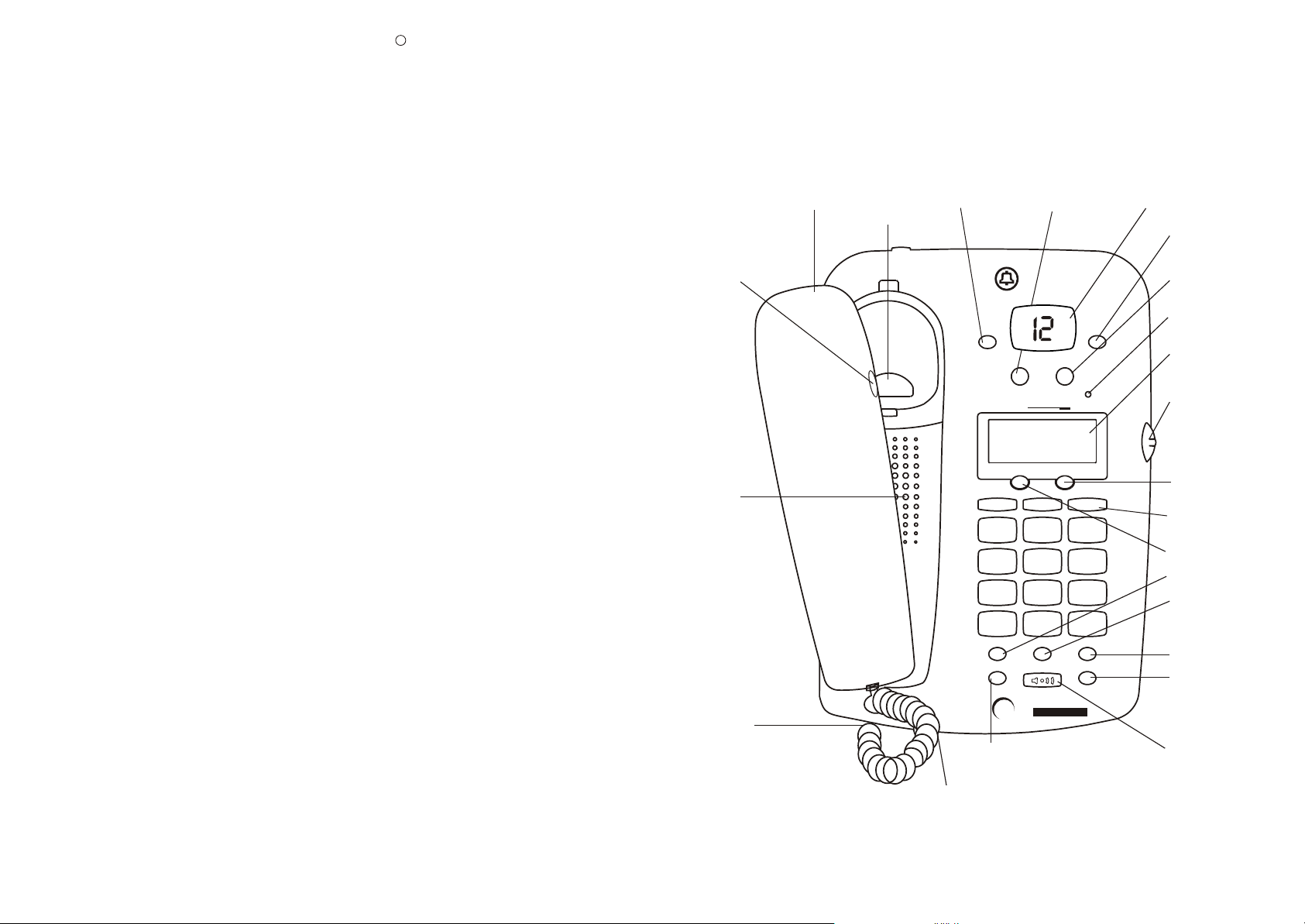
Location of Controls
TOP VIEW:
Handset
Handset Receiver
Volume Control
Speaker
Coil Cord
Off Hook
Handset Reset
Stop
Answer On/Off/Erase
STOP TIME SET/REPEAT
M1 M2
1
GHI
4
PQRS
7
*
MEMORY
MUTE
Mute
Microphone
Southwestern Bell
Freedom Phone
PLAY
SKIP/MEMO
ERASE
ANSWER ON/OFF/ERASE
Caller ID
ERASE
ABC
2
JKL
5
TUV
8
OPER
0
STORE
SPEAKER
D I G I T A L
call
ANSWERING SYSTEM
waiting
P
L
A
Y
GREETING
CALL BACK
M3
DEF
3
MNO
6
WXYZ
9
#
REDIAL/PAUSE
FLASH
Play/Skip/Memo
NEW CALL
R
E
V
I
E
W
Time Set/Repeat
Greeting
New Call LED
LCD Display
Caller ID
Review Knob
Caller ID
Redial/Call Back
Memory
Button 1, 2, 3
Caller ID Erase
Memory
Store
Redial/Pause
Flash
Speakerphone
2
3
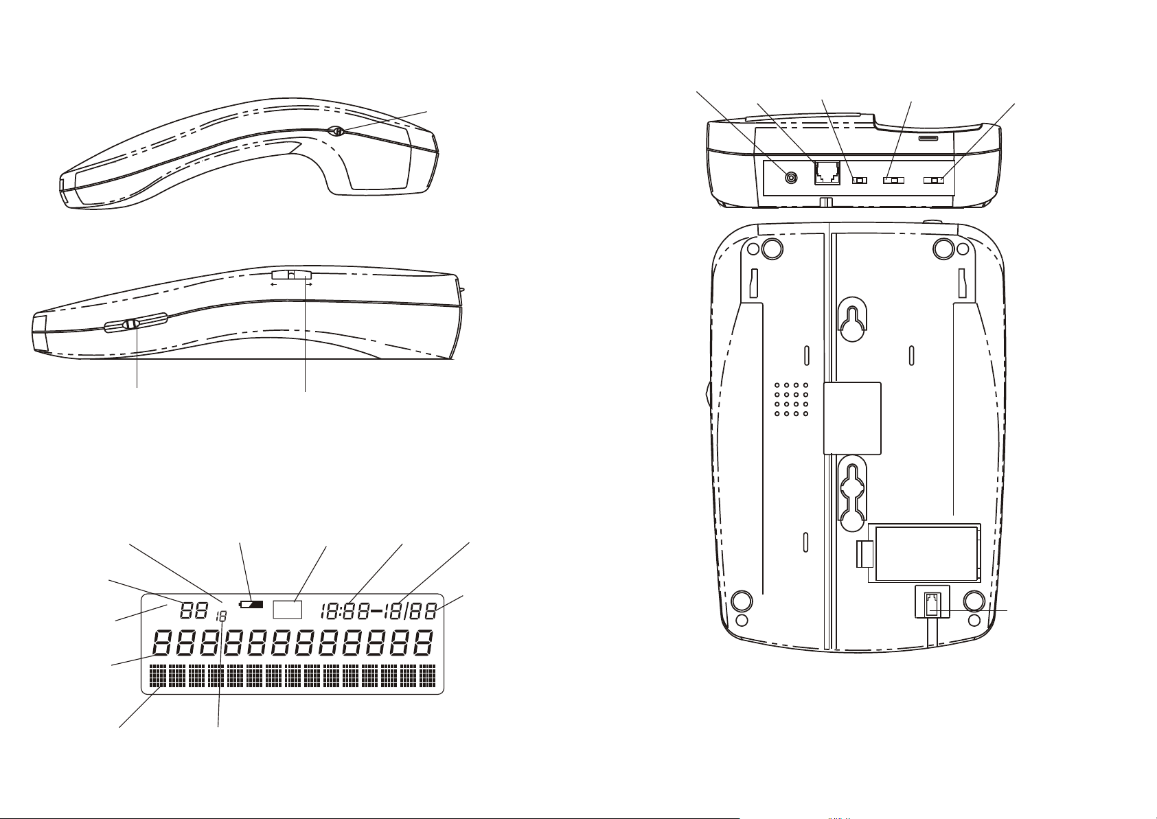
Location of Controls (Cont.)
SIDE VIEW:
Location of Controls (Cont.)
REAR VIEW:
AC Adaptor 9V
R
E
C
EI
VE
R
N
O
R
M
/H
I
GH
Receiver Volume
Control
AC200mA Jack
Telephone
Line Jack
Pulse/Tone
Switch
Ringer/Off/Low/High
Switch
Ring Select
(2,4,TS) Switch
E
M
LU
O
V
H
IG
LOW H
Speakerphone Volume Control
LCD DISPLAY:
Repeat Call Icon
Battery Low Icon Month
REVIEW
Caller ID Review Knob
VIP Icon
Time
BOTTOM VIEW:
AC9V
RINGER
PULSE/TONE 2/4/TS
OFF/LOW/HIGH
Call Counter
New Call Icon
Call Number
Display
NEW
CALL
Repeat Call CounterCall Name Display
RPT
4
VIP
PM
AM
Day
Coil Cord Jack
PLEASE READ IMPORTANT SAFETY INSTRUCTIONS
ON PAGE 6 BEFORE USE.
Congratulations!
You have purchased an Integrated Speakerphone Telephone With Caller ID/Call Waiting and
Digital Answering System manufactured to the highest standards of SOUTHWESTERN
BELL FREEDOM PHONE RETAIL SALES. You will enjoy the benefits of its
deluxe features, which you can operate conveniently and accurately.
®
5

IMPORTANT SAFETY INSTRUCTIONS
Safety Instructions for Batteries
BEFORE USING YOUR TELEPHONE EQUIPMENT, BASIC SAFETY PRECAUTIONS
SHOULD ALWAYS BE FOLLOWED TO REDUCE THE RISK OF FIRE, ELECTRIC
SHOCK AND INJURY, INCLUDING THE FOLLOWING:
1. Read and understand all instructions.
2. Follow all warnings and instructions marked on the product.
3. Unplug this product from the wall telephone jack and power outlet before cleaning.
Do not use liquid cleaners or aerosol cleaners. Use a damp cloth for cleaning.
4. Do not use this product near water, for example, near a bathtub, washbowl, kitchen
sink, or laundry tub, in a wet basement, or near a swimming pool.
5. Do not place this product on an unstable cart, stand or table. The product may fall,
causing serious damage to it.
6. Slots and openings in the cabinet and the back or bottom are provided for ventilation,
to protect it from overheating. These openings must not be blocked or covered. The
openings should never be blocked by placing the product on a bed or other similar
surface. This product should never be placed near or over a radiator or heat register.
7. This product should be operated only from the type of power source indicated
on the marking label. If you are not sure of the type of power supply to your home,
consult your dealer or local power company.
8. Do not allow anything to rest on the power cord. Do not place this product where
the cord will be abused by persons stepping on it.
9. Do not overload wall outlets and extension cord, as this can result in fire or electric
shock.
10. Never push objects of any kind into this product through cabinet slots, as they may
touch dangerous voltage points or short out parts that could result in fire or electric
shock. Never spill liquid of any kind on the product.
11. To reduce the risk of electric shock, do not disassemble this product, but take it to
a qualified serviceman when some service or repair work is required. Opening or
removing covers may expose you to dangerous voltages or other risks. Incorrect
reassembly can cause electric shock when the appliance is subsequently used.
12. Unplug this product from the wall outlet and refer servicing to qualified service
personnel under the following conditions:
a. When the power supply cord or plug is damaged or frayed.
b. If liquid has been spilled into the product.
c. If the product has been exposed to rain or water.
d. If the product does not operate normally by following the operating instructions.
Adjust only those controls that are covered by the operating instructions because
improper adjustment of other controls may result in damage and will often require
extensive work by a qualified technician to restore the product to normal operation.
e. If the product has been dropped or the cabinet has been damaged.
f. If the product exhibits a distinct change in performance.
13. Avoid using a telephone (other than a cordless type) during an electrical storm.
There may be a remote risk of electric shock from lightning.
14 Do not use the telephone to report a gas leak in the vicinity of the leak.
Save These Instructions
6
CAUTION
TO REDUCE THE RISK OF FIRE OR INJURY TO PERSONS, READ AND
FOLLOW THESE INSTRUCTIONS.
1. Use only the size and type of batteries mentioned in the Owner's Manual.
2. Do not dispose of the batteries in a fire. The cells may explode. Check with local
codes for possible special disposal instructions.
3. Do not open or mutilate the batteries. Released electrolyte is corrosive and may
cause damage to the eyes or skin. It may be toxic if swallowed.
4. Exercise care in handling batteries in order not to short the batteries with
conducting materials such as rings, bracelets, and keys. The batteries or conductors
may overheat and cause burns.
5. Do not attempt to recharge the batteries identified for use with this product.
The batteries may leak corrosive electrolyte or explode.
6. Do not attempt to rejuvenate the batteries identified for use with this product by
heating it. Sudden release of the battery electrolyte may occur, causing burns or
irritation to eyes or skin.
7. When replacing batteries, all batteries should be replaced at the same time.
Mixing fresh and discharged batteries could increase internal cell pressure and rupture
the discharged batteries.
8. When inserting batteries into this product, the proper polarity or direction must
be observed. Reverse insertion of the batteries can cause charging, and that may
result in leakage or explosion.
9. Remove the batteries from this product if the product will not be used for a long
period of time (several months or more) since during this time the batteries could
leak in the product.
10. Discard "dead" batteries as soon as possible since "dead" batteries are more
likely to leak in a product.
11. Do not store this product, or the batteries identified for use with this product, in
high-temperature areas. Batteries that are stored in a freezer or refrigerator for the
purpose of extending shelf life should be protected from condensation during storage
and defrosting. After cold storage, batteries should be stabilized at room temperature
prior to use.
7
General Information
Telephone Installation
UNPACKING
This package contains:
• FM2575 Telephone with Caller ID/Call Waiting and Digital Answering System
• One (1) AC Adaptor 120V AC
• Owner's manual
• One (1) Desk Mount Bracket
• One (1) Fully Modular Coil Cord
• One (1) Long Fully Modular Telephone Line Cord (Long Straight Cord)
• One (1) Short Fully Modular Telephone Line Cord (Short Straight Cord)
• One (1) Quick Reference Guide
• Warranty Card (Part Of Owner's Manual)
• Remote Access Card
If anything is missing or damaged, contact the place of purchase. Keep the
packaging to transport the telephone.
Helpful Tips From Customer Service
1. You must subscribe to Caller ID and Call Waiting service from your local
telephone company for your FM2575 to operate.
2. Remove the "peel off label" covering the FM2575's display.
3. Plug one end of the telephone line cord into the TELEPHONE LINE jack on the
FM2575 and the other end into the modular outlet in your telephone wall jack.
4. Plug the AC Power Adapter into the FM2575 before connecting it to the wall outlet.
5. Make sure you can read the display clearly. Adjust the display contrast by pressing
and holding the CALL BACK and ERASE buttons at the same time for 2 seconds.
Rotate the "REVIEW" knob to select the contrast. Press ERASE to confirm the contrast.
Installation
CAUTION
1. Never install telephone wiring during a lightning storm.
2. Never install telephone jacks in wet locations unless the jack is specifically
designed for wet locations.
3. Never touch uninsulated telephone wires or terminals unless the incoming
telephone line has been disconnected at the network interface.
4. Use caution when installing or modifying telephone lines.
Note: Refer to "FCC Requirements" section on page 28 before connection to
telephone line.
8
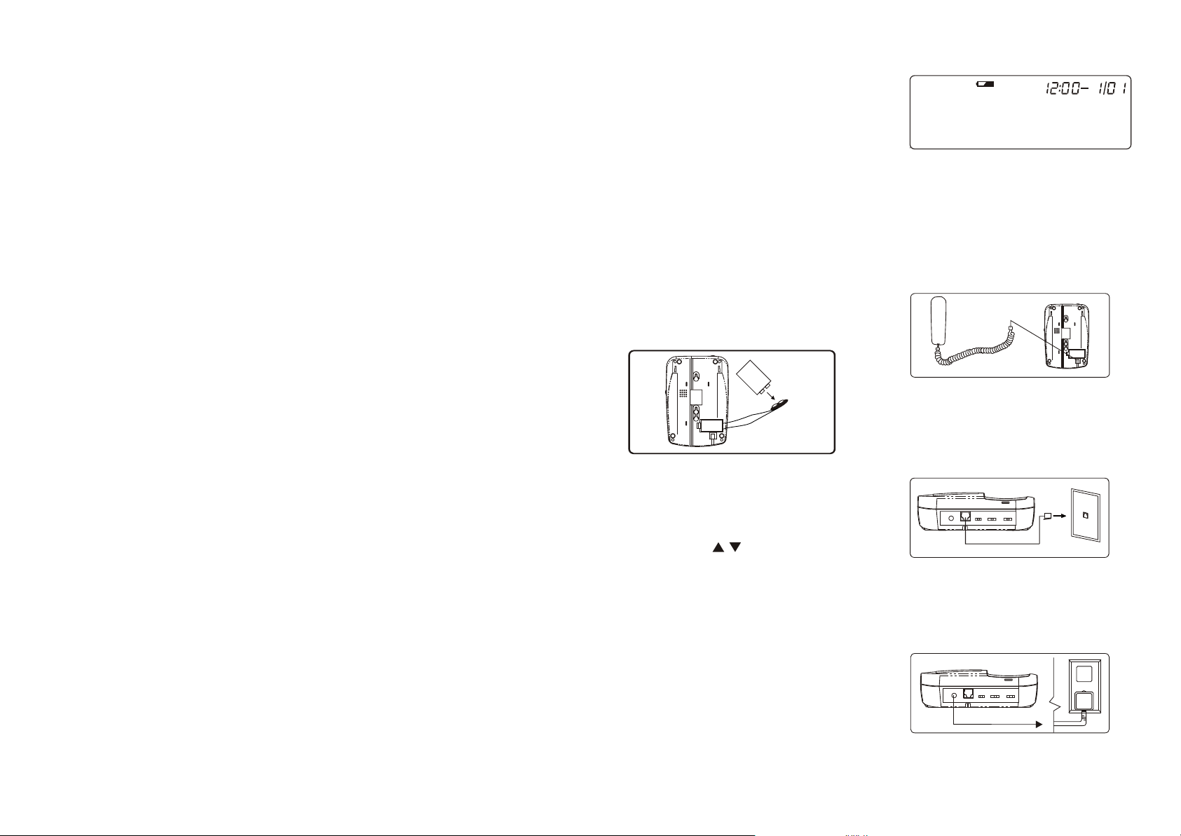
Battery Installation
1. Insert a ball point pen into the hole
located in the battery compartment door
(on the bottom of the base). This will
loosen the door, and you should lift the
battery compartment door.
2. Install one 9V Alkaline battery. One 9
volt battery (not included) is required to
maintain your personalized greeting and
recorded messages during a power failure.
If there is a power failure and the battery
is not installed, both your personalized
greeting and recorded messages will be lost.
NOTE: You must install 9 volt battery
in order for the Caller ID and Telephone
operation to function properly.
Battery
Battery
9V
9V
Figure A
3. Replace battery compartment door and
snap into place.
Note: After installing a 9V battery,
system displays "SET
LANGUAGE ". Your FM2575
enters setting mode. (See Setting Up
Your FM2575 section for details.)
Replace a new 9V alkaline battery
when the Battery Low Indicator
(BATTERY LOW ICON) appears on the
LCD display. The battery level is indicated
by the presence of the battery indicator
during normal operation. If the 9 Volt
battery is low or has been installed
incorrectly, the battery low indicator will
appear on the LCD display. (Fig. B)
AM
Figure B
Choose Your Location
Before making any connections, install
the FM2575 near an AC power outlet and
a telephone wall jack (RJ11C).
Desk or Table Installation
1. Connect the COIL CORD into the jack on
the bottom of the base (Fig. C).
Figure C
2. Plug one end of the telephone line
cord into the TELEPHONE JACK located
on the back of the FM2575, and the other
end into the modular outlet in your
telephone wall jack (Fig. D).
Figure D
3. Connect the AC adaptor into the AC
ADAPTOR JACK on the back of the base
and into the AC wall power outlet. Do
not attach (staple, etc.) the power supply
cord to the building wall (Fig. E).
Figure E
AC
ADAPTER
The Message Counter will then countdown
from 9 to 0. The unit is checking its memory,
and you should not press any buttons.
9
Telephone Installation (Cont.)
When you plug in your unit for the first
time, it will take approximately 14
seconds for the unit to check its memory
(It will announce "Wait For Operation").
When the memory check is complete,
your system will announce "Unit Ready"
and will reset to answer incoming calls.
It will answer incoming calls with a
prerecorded greeting; "Hello,We are not
available now; please leave your name
and number after the beep." To record a
personalized greeting refer to page 15.
4. Connect the desk mount bracket to the
bottom of the base. This will tilt the base
for enhanced Caller ID visibility.
Wall Mounting On a Wall Plate
1. Connect the coil cord into the handset
jack and the jack on the bottom of the unit.
2. Connect the AC adaptor into the AC
ADAPTOR JACK on the bottom of the
unit and plug the other end into the
110/120 volt outlet.
3. Connect the short telephone line cord
to the modular jack located on the bottom
of the base. Insert the other end into the
wall jack, making sure it snaps firmly in
place (Fig.F).
Figure F
4. Position the bottom of the base over the
two studs of the wall plate. Pull down to
lock in place (Fig.F).
On Two Screws
1. Fasten two screws into the wall,
placing them 3-1/4" apart vertically.
They should extend 3/16" from the wall.
2. Connect the coil cord into the handset
jack and the jack on the bottom of the
unit.
3. Connect the AC adaptor into the AC
ADAPTOR JACK on the bottom of the
unit and plug the other end into the
110/120 volt outlet.
4. Simply connect the long telephone line
cord to the modular jack and thread through
the groove on the bottom of the unit.
(Fig.G)
5. Mount the unit by fitting the two
screws into the keyway holes on the
bottom of the base. Pull down gently
for a snug fit. The LINE CORD should
hang down behind the unit.
6. Plug the LINE CORD into the wall
modular jack.
10
Figure G
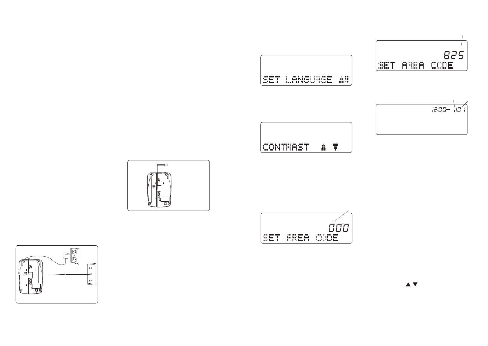
Setting Up Your FM2575
To Set Language
1. If "SET LANGUAGE" is not displayed on
the screen, press and hold CALL BACK
Button for 2 seconds. The LCD display
will show:
2. Rotate the "REVIEW" knob to select
English, French or Spanish.
3. Press the"ERASE" Button to confirm
the language selected. The unit will
then proceed to the contrast setting mode.
To Set LCD Display Contrast
1. Rotate the "REVIEW" knob
clockwise to make the contrast
lighter or counter clockwise to
make the contrast darker.
2. Press "ERASE" Button to confirm
selection.The unit will then proceed
to the area code setting mode.
To Set Area Code
Note: In order for the Caller ID Redial
feature to work properly, you must set
your area code.
1. Rotate the "REVIEW" knob
clockwise or counter clockwise
until you have entered the correct
first digit of your local area code.
Press the "ERASE" Button to move
to the next digit.
2. Repeat step 1 for the programming of
the second and third digits of your
local area code.
flash
11
flash
3. Press the "ERASE" Button again to
end the setting. The display will show
the default time and day. The unit is
now ready to receive calls.
Month Day
AM
The correct date and time are automatically
set when your FM2575 receives its first
call.
Note:
1. If you try to use the telephone before
finishing the Caller ID set up, or if
you pause more than 40 seconds during
any of the above steps, the display will
show "SET LANGUAGE" to remind
you to finish this sequence.
2. To set up your FM2575 again, press and
hold the "CALL BACK" Button for 2
seconds to restart setup.
3. If you only want to adjust the LCD
display contrast in standby mode or in
review mode, press and hold the
"CALL BACK" and "ERASE" Button at
the same time. LCD will show
"CONTRAST , to indicate that
"
your FM2575 has entered contrast
setting mode.
 Loading...