

Southwest Building Supply 24"" Kiva, SWK24 Installation Instructions And Operation Manual
This fireplace is to be installed ONLY by a
construction industry licensed contractor, or an
installer certified by Southwest KIVA Inc. Any
permits required for installation should be
obtained by contractor as well as any other
construction industry inspections that may be
required.
WARNING The information outlined in this
installation manual must be adhered to by the
installer and the buyer exactly, failure to do so
and may cause a serious fire hazard resulting in
property damage, personal injury or loss of life.
It will also void the warranty.
WARNING: The glass door is tempered glass
and is only used when the fireplace has been
converted to burn gas ceramic logs. The door is
only to be used to prevent draft, and should not
be in place when burning.
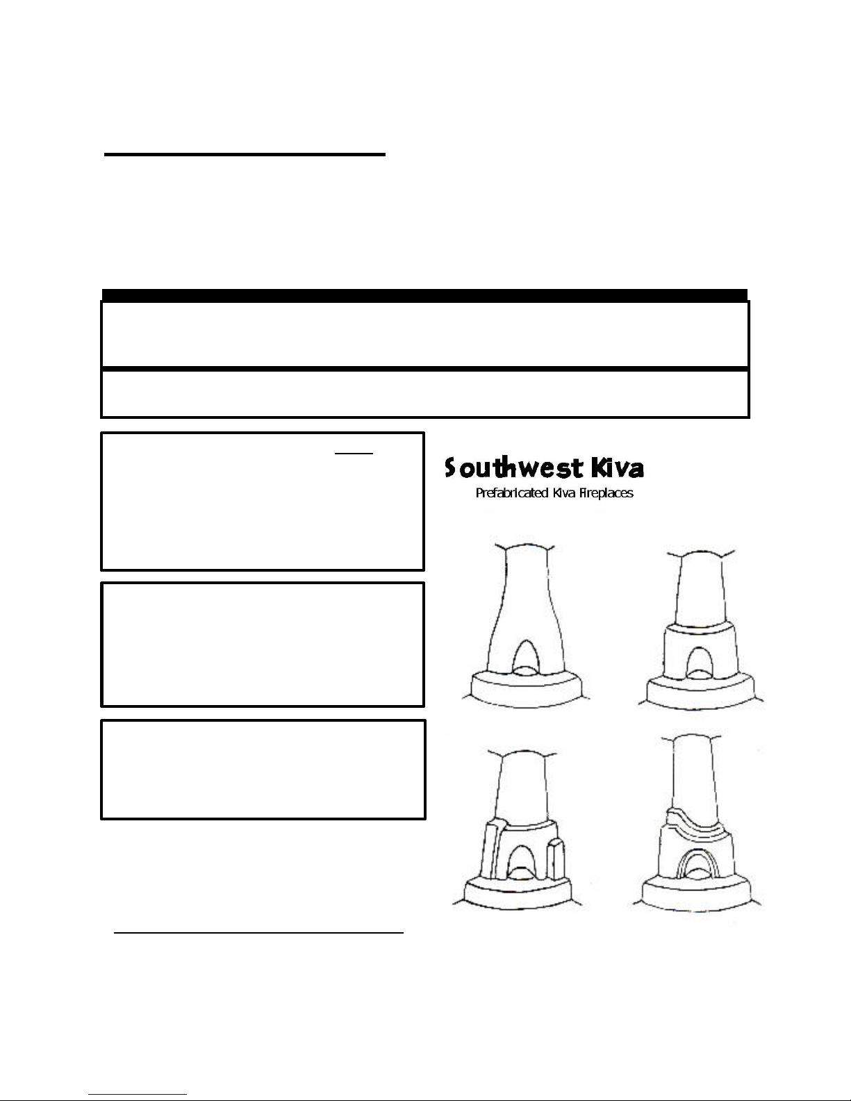
24” KIVA FIREPLACE
Prefabricated Masonry Wood Burning Firebox and Metal FramePrefabricated Masonry Wood Burning Firebox and Metal Frame
INSTALLATION INSTRUCTIONS AND OPERATIONS
Firebox Model SWK24 Frame Models SWKL24-LAGUNA
(Figure 1) SWKS24-SANDIA
SWKH24-HOPI
SWKSH24-SHALAKO
SAVE THIS BOOK
In addition to instructions on installation and maintenance of your fireplace it contains information that
will make it easier to obtain replacement parts as needed.
This fireplace is approved for use as a wood burning fireplace or for use with vented gas logs approved
to ANSI Z21.60 standards.
Sold by
Southwest Building Supply
Rio Rancho, NM 87124
www.SouthwestBuildingSupply.com
“Laguna”
“Hopi”
Figure 1
“Sandia”
“Shalako”
1
1

Table of Contents
I. Introduction……………………... .....................…............… 3
II. Firebox Installation Procedure ...........................................… 3
III. Combustible Air System…………………............................… 6
IV. Chimney Installation...........................................................… 7
V. Frame Installation ................................................................… 11
VI. Door Frame Installation ......................................................… 11
VII. Finishing / Plastering the Fireplace ....................................… 12
VIII. Gas Pipe Installation …………………………………………… 12
Parts List and Options ........................................................……… 13
ALL PICTURES/CHARTS RELATED TO CHIMNEY COMPONENTS ARE REPRODUCED W ITH THE PERMISSION OF DESA
INTERNATIONAL.
2
2
I. INTRODUCTION
FOR YOUR SAFETY
Do not store or use gasoline in the vicinity of this or any other appliance.
Due to high temperatures, the appliance should be located out of traffic and away
from furniture and draperies.
Do not place clothing or other flammable materials on or near the appliance.
NEVER leave children unattended when a fire is burning in the fireplace
CHECK LOCAL CODES BEFORE INSTALLING THIS FIREPLACE.
This wood burning fireplace complies with UL 127 standard as a FACTORY BUILT FIREPLACE.
Warning this fireplace has not been tested with an unvented gas log set. To reduce risk of fire or injury, do
not install an unvented gas log into fireplace
WARNING: Do not install fireplace insert in this firebox unless the manufacturers instructions with the insert
specifically state the Southwest Kiva fireplace has been tested for the insert.
Before you begin installation of this fireplace, read these instructions completely.
This fireplace and its components are safe when installed according to the installation manual.
Unless Southwest KIVA parts are used, which have been tested and approved for this fireplace, a fire
hazard may result.
The Southwest KIVA warranty will be voided and Southwest Firebird, Inc. disclaims any responsibility for the
following infractions:
1. Any modification of the fireplace, components, doors, air inlet system, or damper control.
2. Use of any part not manufactured/approved by Southwest Firebird, Inc.
PROPER PREPARATION prior to fireplace installation is very important to ensure
safety and continuous operation. Consult the local building codes for specific
requirements for your area.
SELECTING A LOCATION
To determine the safest and most efficient location for the fireplace the following guidelines must be taken into consideration.
1. The location must allow for proper clearances (See Pages 5 & 7).
2. The location of the fireplace should not be affected by drafts, air conditioning ducts, windows or doors.
3. A location where the cutting of joists, or roof rafters can be avoided.
4. The required outside air kit can be easily installed (See Page 6).
II. FIREBOX INSTALLATION
When installing the firebox, it must be placed on a level non-combustible surface. If the existing floor surface is wood, vinyl
or any combustible material, the flooring needs to be protected with ½” x 4’6”x 4’6” masonry board to the full dimension of
the frame/cage (if used). A minimum of 18” clearance from the firebox opening to any combustible is required.
3
3
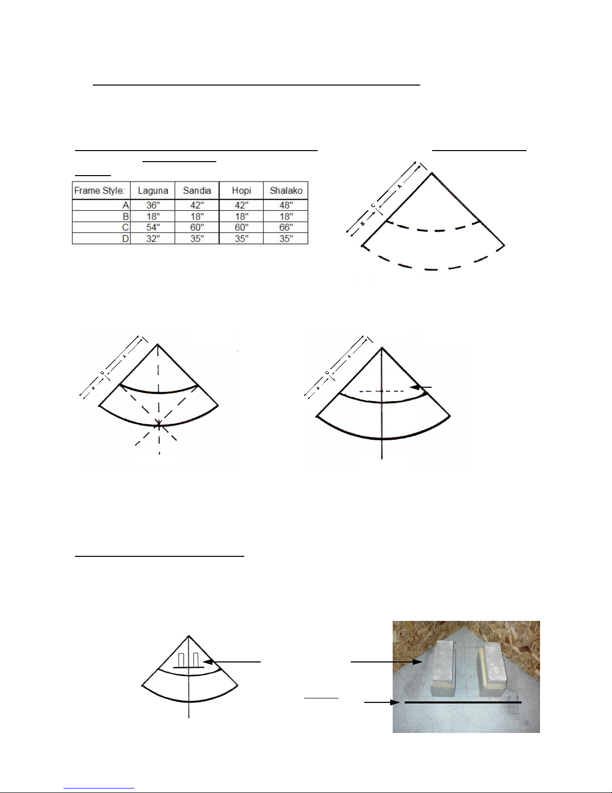
A. FRAME LAYOUT (if used) AND FIREBOX BASE PEDESTAL PLACEMENT
8x8 & 4x8 CMU Blocks
In the corner, where the fireplace is to be installed, measure out along adjacent wall the appropriate distance
as shown in (Chart A, Row C). Do the same on the opposite wall. Draw a line on the floor with chalk or pencil
to create the arch radius of the hearth/banco. Repeat the procedure for firebox radius (Chart A, Row A). See
Figure 2.
If any carpeting and/or padding is present, it should be re- moved to the radius of
the hearth/banco.
Chart A
Figure 2
To find the centerline, draw a straight line out from walls at firebox radius (Chart A, Row A). See Figure 3.
Figure 3
Figure 4
Bottom Section Front Line D
Centerline
Centerline
To place the front of firebox bottom section, make a mark on the centerline out from the corner according to
Chart A, Row D (example: Laguna = 32”). With a carpenter’s square draw a perpendicular line 1 foot out
from this mark on both sides of the line. See Figure 4.
B. BASE PEDESTAL PREPARATION
Assemble two columns of blocks by placing one 8"x8"x16" and one 4"x8"x16" (blocks, not provided) on the
bottom section front line, 3" away from centerline as illustrated in Figure 5. Mortar or adhere blocks together
and to the floor. If a frame is not being used, the base may be set at desired height using alternate block size
combinations.
Figure 5
4
See Chart A above
for D dimension
4
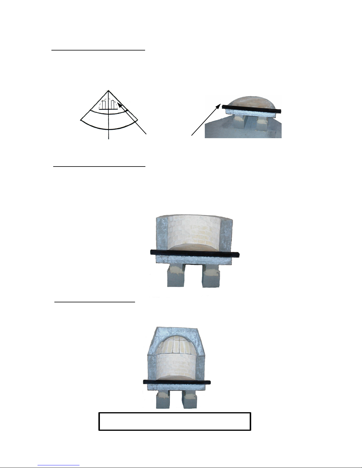
C. BOTTOM SECTION INSTALLATION
WARNING DO NOT PACK REQUIRED AIR SPACE
WITH INSULATION OR OTHER MATERALS.
Spread a thin coat of high temperature refractory mortar (provided) to the top of the pedastal blocks. Set the
bottom section on top of blocks and line the front up with the bottom section front line drawn on the floor. The
clearance between the sides/back of the firebox to the side/back wall should be at a minimum of 2”. See Figure 6.). Repeat on other side. Level section and realign to the front of the bottom section front line.
Figure 6
Min. 2” Clearance
between firebox & wall.
D. CENTER SECTION INSTALLATION
Place center section on top of the bottom section. Draw a line on the interior of the bottom section along the
brick curve, outlining the curve. Remove the center section and spread refractory mortar 1” behind the line
drawn on the bottom section. Reset the center section, press into position, and align with the back and sides
of the bottom section. Spread a thin coat of mortar on the outside edge, or seam, to seal the two pieces together where they connect. Remove any excess refractory mortar or add mortar as needed to fill voids.
E. TOP SECTION INSTALLATION
Spread the refractory mortar to the top of the center section, and then follow the same procedure as
the center section required. Including applying mortar to the outside seam.
5
5
 Loading...