

Southern States VM-1 Installation Instructions Manual
INSTRUCTION
INSTALLATION &
MANUAL
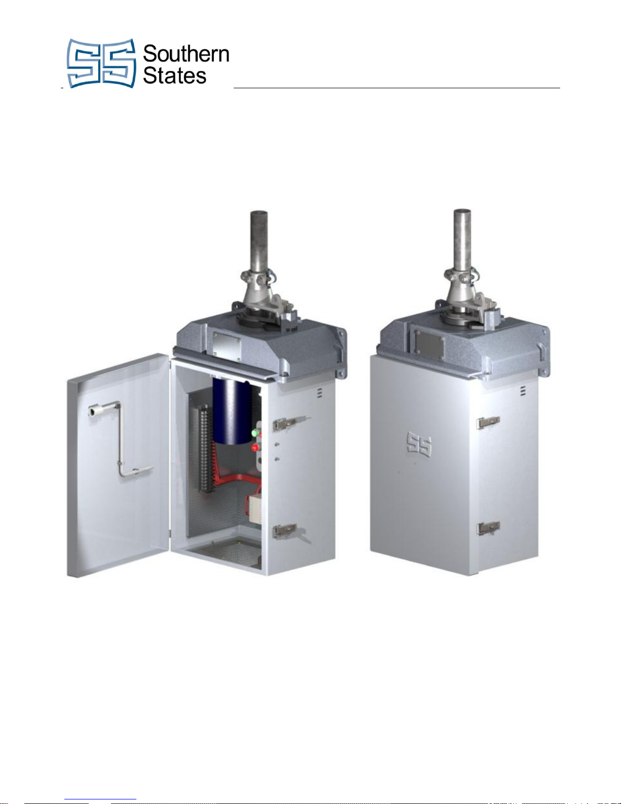
Type VM-1
Motor Operator
All Ratings

The Quality Name in High Voltage Switching
IMPROPER HANDLING, INSTALLATION, OPERATION OR MAINTENANCE OF THIS EQUIPMENT MAY
CAUSE IMMEDIATE HAZARDS WHICH WILL LIKELY RESULT IN SERIOUS PERSONNEL INJURY OR
DEATH.
The equipment covered by this publication must be handled, installed, operated and maintained by qualified
persons who have direct knowledge and experience dealing with the hazards involved and are thoroughly
trained in the handling, installation, operation and maintenance of high voltage transmission and distribution
equipment. These instructions are meant for only such Qualified Persons. They are not intended to be a
substitute for adequate training and experience in safety procedures for this type of equipment.
A Qualified Person is one who is trained in and has skills necessary:
to read and comprehend this instruction book – understanding that these instructions are general in
nature
to accept personal responsibility to prepare and maintain an intrinsically safe work environment and
maintain control of the work site to safeguard all persons present
to develop and implement a proper rigging, lifting, and installation plan along with all safety
precautions required to insure safe and proper lifting and installation of the equipment.
to distinguish between energized and non energized parts
to determine proper approach distances to energized parts
to properly work with and around energized or de-energized equipment that may be pressurized
with gas
for proper use of personal protective equipment, insulating and shielding materials, insulated tools
for working near energized and /or pressurized electrical equipment
to recognize and take necessary precautions for the unique and dynamic conditions of site and
specialized equipment to maintain a safe work environment during handling, installation, operation,
and maintenance of high voltage switching equipment
The instructions in this manual are general guidelines for this type of equipment and not specific to the
equipment supplied. Portions of it may not be applicable or may not have complete instructions for your
specific equipment.
If you do not understand any part of these instructions or need assistance, contact Southern States Service
Division at 770-946-4562 during normal business hours (8:00am – 4:30pm EST, M-F) or 770-946-4565 after
normal business hours.
The Quality Name in High Voltage Switching
Safety Information
Product Purchased
Region
Product Installed
Region
Warranty Holder
Warranty Duration
U.S and Canada
U.S and Canada
End User
Five (5) Years
All Other Conditions
Immediate
Purchaser
Earlier of 1 year from
installation or 18 months
from shipment
The Quality Name in High Voltage Switching
LIMITED WARRANTY
Southern States, LLC (“SSLLC”) warrants only to the Warranty Holder (hereinafter defined as the “End User”
or the “Immediate Purchaser”, as applicable, pursuant to the terms and conditions of this Limited Warranty as
set forth below), that the Product identified below will, upon shipment, be free of defects in workmanship and
material for the applicable Warranty Period. The “Warranty Period” is that period of time during which this
Limited Warranty is effective, and such period begins on the invoice date issued by SSLLC for the Product,
and continues until the earlier to occur of (1) the expiration of the Warranty Duration period, or (2) the Number
of Operations, both as specified in the table below. If the Product is both purchased and installed within the
United States or Canada, this Limited Warranty is granted to each end user of the Product who acquired the
Product for its own use during the Warranty Period (“End User”). In all other situations, this Limited Warranty
is granted only to the first purchaser of the Product (“Immediate Purchaser”) from SSLLC. No primary or
remote purchaser or owner of the Product who is not a Warranty Holder may claim any benefit under this
Limited Warranty, or any remedial promise included in this Limited Warranty. SSLLC shall, upon prompt
written notice from the Warranty Holder, correct a nonconforming Product by repair or replacement at the sole
discretion of SSLLC of the nonconforming Product or any part or component of a nonconforming Product
necessary in SSLLC’s discretion to make such Product conforming. Any transportation charges, labor for
removing, reinstalling the Product or part, and/or costs related to providing access to the Product shall be the
responsibility of the Warranty Holder. Correction in this manner will constitute the Warranty Holder’s exclusive
remedy and fulfillment of all SSLLC’s liabilities and responsibilities hereunder. SSLLC’s duty to perform under
this limited warranty may be delayed, at SSLLC’s sole option, until SSLLC has been paid in full for all products
purchased by the Warranty Holder. No such delay will extend the Warranty Period. If SSLLC does not make
such repair or replacement, SSLLC’s liability for damages on account of any claimed nonconformity will in no
event exceed the purchase price of the Product in question. This Limited Warranty does not apply to any
Product that has been disassembled, repaired, or altered by anyone other than SSLLC. This Limited Warranty
will not apply to any Product that has been subjected to improper or abnormal use of the Product. SSLLC has
no responsibility to repair or replace any Product or component thereof manufactured by another party, but
SSLLC will assign, to the extent assignable, to the Warranty Holder any manufacturers’ warranty that applies
to products and components not manufactured by SSLLC.
THIS LIMITED WARRANTY IS EXCLUSIVE AND IN LIEU OF ALL OTHER WARRANTIES. THERE
ARE NO OTHER EXPRESS, IMPLIED, OR STATUTORY WARRANTIES. ALL IMPLIED
WARRANTIES WHICH MAY ARISE BY IMPLICATION OF LAW, OR APPLICATION OF COURSE OF
DEALING OR USAGE OF TRADE, INCLUDING, BUT NOT LIMITED TO, IMPLIED WARRANTIES OF
MERCHANTABILITY OR FITNESS FOR A PARTICULAR PURPOSE, NONINFRINGEMENT OR
OTHERWISE ARE EXPRESSLY EXCLUDED. SSLLC SHALL NOT BE LIABLE OR RESPONSIBLE
FOR ANY CONSEQUENTIAL, INCIDENTAL, INDIRECT, EXEMPLARY, SPECIAL, OR PUNITIVE
DAMAGES, EVEN IF SSLLC HAS BEEN ADVISED OF THE POSSIBILITY OF SAME. THE
WARRANTY HOLDER IS SOLELY RESPONSIBLE FOR THE SUITABILITY OF THE PRODUCT FOR
ANY PARTICULAR APPLICATION.
Revised 7/14/15
The Quality Name in High Voltage Switching
TYPE VM-1

Important
The information contained herein is general in nature and not intended for specific application purposes. It
does not relieve the user of responsibility to use sound practices in application, installation, operation, and
maintenance of the equipment purchased. Southern States reserves the right to make changes in the
specifications shown herein or to make improvements at any time without notice or obligations. Should a
conflict arise between the general information contained in this publication and the contents of drawings or
supplementary material, or both, the latter shall take precedence.
Installation and Adjustment Procedures
Chapter Page
Introduction ........................................................................................................................................................... 3
Important ............................................................................................................................................................... 3
Unpacking: ............................................................................................................................................................ 4
Installation: ............................................................................................................................................................ 5
Electrical Check-Out Procedure: ........................................................................................................................... 7
Adjusting Switch Operation to VM-1 Rotation: ...................................................................................................... 8
Manual Operation:................................................................................................................................................. 9
Electrical Operation: .............................................................................................................................................. 9
Changing Output Rotation: ................................................................................................................................. 10
Auxiliary Switch Adjustment: ............................................................................................................................... 11
Reverse Motor Rotation: ..................................................................................................................................... 14
Swing Handle Attachment: .................................................................................................................................. 14
Maintenance: ....................................................................................................................................................... 14
Figures Page
Figure 1 - Part Identification .................................................................................................................................. 4
Figure 2 - Decoupler ............................................................................................................................................. 6
Figure 3 - Decoupler Operation ............................................................................................................................ 7
Figure 4 - Manual Operation ................................................................................................................................. 9
Figure 5 - Re-Position Locking Plate Manually ................................................................................................... 10
Figure 6 - Rotate with Crank Handle to Desired Position ................................................................................... 10
Figure 7 - Auxiliary Switch .................................................................................................................................. 12
Figure 8 - CCW – LS ........................................................................................................................................... 13
Figure 9 - CW – LS ............................................................................................................................................. 13
Figure 10 - Vertical Pipe Rotates CCW to Open. ............................................................................................... 13
Figure 11 - Vertical Pipe Rotates CCW to Open. ............................................................................................... 13
Figure 12 - Vertical Pipe Rotates to CW To Open. ............................................................................................. 13
Figure 13 - Vertical Pipe Rotates CW to Open. .................................................................................................. 13
Figure 14 - Swing Handle Attachment ................................................................................................................ 14
3
 Loading...