

Southern States SPGT25H54 Operator's Manual
OPERATOR'S MANUAL
MODEL NO. SPGT25H54
25.0 HP 54 INCH
GARDEN TRACTOR
• Assembly
° Operation
° Maintenance
° Service and Adjustments
° Storage
• Troubleshooting
• Espa_ol
For Parts and Service, contact our authorized distributor:
call 1-800-849-1297 ForTechnical Assistance: call 1-800-829-5886
i
SOUTHERN STATES
195494 Rev. 2 08.03.05 RD/TR
PRINTED IN U.S.A.

Warranty ................................................ 2
Safety Rules .......................................... 3
Product Specifications ........................... 6
Assembly/Pre-Operation ....................... 8
Operation ............................................. 12
Maintenance ....................................... 19
Maintenance Schedule ........................ 19
Service and Adjustments ..................... 23
Storage ................................................ 29
Troubleshooting ................................... 30
EspaSol ................................................ 34
LIMITED WARRANTY
The Manufacturer warrants to the original consumer purchaser that this product as
manufactured is free from defects in materials and workmanship. For a period of two
(2) years from date of purchase by the original consumer purchaser, we will repair or
replace, at our option, without charge for parts or labor incurred in replacing parts, any
part which we find to be defective due to materials or workmanship. This Warranty is
subject to the following limitations and exclusions.
1. This warranty does not apply to the engine, other than EHP manufactured transaxle/
transmission components, battery (except as noted below) or components parts
thereof. Please refer to the applicable manufacturer's warranty on these items.
2. Transportation charges for the movement of any power equipment unit or attachment
are the responsibility of the purchaser. Transportation charges for any parts submit-
ted for replacement under this warranty must be paid by the purchaser unless such
return is requested by Electrolux Home Products.
3. Battery Warranty: On products equipped with a Battery, we will replace, without
charge to you, any battery which we find to be defective in manufacture, during the
first ninety (90) days of ownership. After ninety (90) days, we will exchange the Bat-
tery, charging you 1/12 of the price of a new Battery for each full month from the date
of the original sale. Battery must be maintained in accordance with the instructions
furnished.
4. The Warranty period for any products used for rental or commercial purposes is
limited to 90 days from the date of original purchase.
5. This Warranty applies only to products which have been properly assembled, ad-
justed, operated, and maintained in accordance with the instructions furnished. This
Warranty does not apply to any product which has been subjected to alteration, mis-
use, abuse, improper assembly or installation, delivery damage, or to normal wear of
the product.
6. Exclusions: Excluded from this Warranty are belts, blades, blade adapters, normal
wear, normal adjustments, standard hardware and normal maintenance.
7. In the event you have a claim under this Warranty, you must return the product to an
authorized service dealer.
Should you have any unanswered questions concerning this Warranty, please contact:
Electrolux Home Products, Inc. In Canada contact:
Outdoor Products Customer Service Dept. Electrolux Canada Corp.
250 Bobby Jones Expressway 7075 Ordan Drive
Augusta, GA 30909 USA Mississauga, Ontario
L5T 1K6
giving the model number, serial number and date of purchase of your product and the
name and address of the authorized dealer from whom it was purchased.
THIS WARRANTY DOES NOT APPLY TO INCIDENTAL OR CONSEQUENTIAL
DAMAGES AND ANY IMPLIED WARRANTIES ARE LIMITED TO THE SAME TIME
PERIODS STATED HEREIN FOR OUR EXPRESSED WARRANTIES. Some areas do
not allow the limitation of consequential damages or limitations of how long an implied
Warranty may last, so the above limitations or exclusions may not apply to you. This
Warranty gives you specific legal rights, and you may have other rights which vary from
locale to locale.
This is a limited Warranty within the meaning of that term as defined in the Magnuson-
Moss Act of 1975.

IMPORTANT:Thiscuttingmachineis capableof amputatinghandsandfeet andthrow-
ingobjects.Failuretoobservethefollowingsafety instructionscouldresultin serious
injuryor death.
WARNING: Inorderto prevent
accidentalstartingwhen settingup,
transporting,adjustingormakingrepairs,
alwaysdisconnectsparkplug wire and
placewirewhereitcannotcontactspark
plug.
WARNING: Do notcoastdowna
hillin neutral,you maylosecontrolof the
tractor.
WARNING: Towonlythe attach-
mentsthatare recommendedbyand
complywithspecificationsofthe man-
ufacturerof your tractor.Usecommon
sensewhentowing.Operateonly at the
lowestpossiblespeedwhenona slope.
Tooheavyof aload,whileon a slope,is
dangerous.Tirescan losetractionwith
thegroundand causeyoutolosecontrol
ofyour tractor.
WARNING:Engineexhaust, some
of its constituents, and certain vehicle
components contain or emit chemicals
known to the State of California to cause
cancer and birth defects or other repro-
ductive harm.
WARNING: Battery posts, terminals
and related accessories contain lead and
lead compounds, chemicals known to the
State of California to cause cancer and
birth defects or other reproductive harm.
Wash hands after handling.
I. GENERAL OPERATION
• Read, understand, and follow all
instructions on the machine and in the
manual before starting.
• Do not put hands or feet near rotating
parts or under the machine. Keep clear
of the discharge opening at all times.
• Only allow responsible adults, who are
familiar with the instructions, to operate
the machine.
• Clear the area of objects such as
rocks, toys, wire, etc., which could be
picked up and thrown by the blades.
• Be sure the area is clear of bystand-
ers before operating. Stop machine if
anyone enters the area.
• Never carry passengers.
• Do not mow in reverse unless abso-
lutely necessary. Always look down
and behind before and while backing.
• Never direct discharged material
toward anyone. Avoid discharging
material against a wall or obstruction.
Material may ricochet back toward the
operator. Stop the blades when cross-
ing gravel surfaces.
• Do not operate machine without the
entire grass catcher, discharge guard,
or other safety devices in place and
working.
• Slow down before turning.
• Never leave a running machine
unattended. Always turn off blades,
set parking brake, stop engine, and
remove keys before dismounting.
• Disengage blades when not mowing.
Shut off engine and wait for all parts to
come to a complete stop before clean-
ing the machine, removing the grass
catcher, or unclogging the discharge
guard.
• Operate machine only in daylight or
good artificial light.
• Do not operate the machine while
under the influence of alcohol or drugs.
• Watch for traffic when operating near
or crossing roadways.
• Use extra care when loading or unload-
ing the machine into a trailer or truck.
• Always wear eye protection when oper-
ating machine.
• Data indicates that operators, age 60
years and above, are involved in a
large percentage of riding mower-re-
lated injuries. These operators should
evaluate their ability to operate the
riding mower safely enough to protect
themselves and others from serious
injury.
• Follow the manufacturer's recommen-
dation for wheel weights or counter-
weights.
• Keep machine free of grass, leaves or
other debris build-up which can touch
hot exhaust / engine parts and burn.
Do not allow the mower deck to plow
leaves or other debris which can cause
build-up to occur. Clean any oil or fuel
spillage before operating or storing the
machine. Allow machine to cool before
storage.
3
I1.SLOPE OPERATION
Slopesarea majorfactorrelatedto lossof
controlandtip-overaccidents,whichcan
resultin severeinjuryor death. Opera-
tionon allslopes requiresextra caution. If
you cannot back up the slope or if you feel
uneasy on it, do not mow it.
• Mow up and down slopes, not across.
• Watch for holes, ruts, bumps, rocks, or
other hidden objects. Uneven terrain
could overturn the machine. Tall grass
can hide obstacles.
• Choose a low ground speed so that
you will not have to stop or shift while
on the slope.
• Do not mow on wet grass.Tires may
lose traction.
Always keep the machine in gear when
going down slopes. Do not shift to
neutral and coast downhill.
• Avoid starting, stopping, or turning on
a slope. If the tires lose traction, dis-
engage the blades and proceed slowly
straight down the slope.
• Keep all movement on the slopes slow
and gradual. Do not make sudden
changes in speed or direction, which
could cause the machine to roll over.
• Use extra care while operating ma-
chine with grass catchers or other at-
tachments; they can affect the stability
of the machine. Do no use on steep
slopes.
• Do not try to stabilize the machine by
putting your foot on the ground.
• Do not mow near drop-offs, ditches,
or embankments. The machine could
suddenly roll over if a wheel is over the
edge or if the edge caves in.
III. CHILDREN
Tragic accidents can occur if the operator
is not alert to the presence of children.
Children are often attracted to the machine
and the mowing activity. Never assume
that children will remain where you last
saw them.
• Keep children out of the mowing area
and in the watchful care of a respon-
sible adult other than the operator.
• Be alert and turn machine off if a child
enters the area.
• Before and while backing, look behind
and down for small children.
• Never carry children, even with the
blades shut off. They may fall off and
be seriously injured or interfere with
safe machine operation. Children who
have been given rides in the past may
suddenly appear in the mowing area
for another ride and be run over or
backed over by the machine.
• Never allow children to operate the
machine.
• Use extra care when approaching blind
corners, shrubs, trees, or other objects
that may block your view of a child.
IV. TOWING
• Tow only with a machine that has a
hitch designed for towing. Do not at-
tach towed equipment except at the
hitch point.
• Follow the manufacturer's recommen-
dation for weight limits for towed equip-
ment and towing on slopes.
• Never allow children or others in or on
towed equipment.
• On slopes, the weight of the towed
equipment may cause loss of traction
and loss of control.
• Travel slowly and allow extra distance
to stop.
V. SERVICE
SAFE HANDLING OF GASOLINE
To avoid personal injury or property
damage, use extreme care in handling
gasoline. Gasoline is extremely flammable
and the vapors are explosive.
• Extinguish all cigarettes, cigars, pipes,
and other sources of ignition.
• Use only approved gasoline container.
• Never remove gas cap or add fuel with
the engine running. Allow engine to
cool before refueling.
• Never fuel the machine indoors.
• Never store the machine or fuel con-
tainer where there is an open flame,
spark, or pilot light such as on a water
heater or other appliances.
• Never fill containers inside a vehicle
or on a truck or trailer bed with plastic
liner. Always place containers on the
ground away from your vehicle when
filling.
• Removegas-poweredequipment from Check their proper operation regularly.
the truck or trailer and refuel it on the Keep machine free of grass, leaves, or
ground. If this is not possible, then other debris build-up. Clean oil or fuel
refuel such equipment with a portable spillage and remove any fuel-soaked
container,dispensernozzle.ratherthan from a gasoline • storing.debrisAllow machine to cool before
• Keep the nozzle in contact with the rim • If you strike a foreign object, stop and
of the fuel tank or container opening at inspect the machine. Repair, if neces-
all times until fueling is complete. Do sary, before restarting.
not use a nozzle lock-open device. • Never make any adjustments or repairs
• If fuel is spilled on clothing, change with the engine running.
clothing immediately. • Check grass catcher components and
• Never overfill fuel tank. Replace gas the discharge guard frequently and
cap and tighten securely, replace with manufacturer's recom-
ENERAL SERVICE mended parts, when necessary.
Never operate machine in a closed blade or wear gloves, and use extra
area. caution when servicing them.
• Keep all nuts and bolts tight to be sure • Check brake operation frequently. Ad-
the equipment is in safe working condi- just and service as required.
tion. • Maintain or replace safety and instruc-
• Never tamper with safety devices, tion labels, as necessary.
• Be sure the area is clear of bystand-
ers before operating. Stop machine if
anyone enters the area.
• Never carry passengers.
• Do not mow in reverse unless abso-
lutely necessary. Always look down
and behind before and while backing.
• Never carry children, even with the
blades shut off. They may fall off and
be seriously injured or interfere with
safe machine operation. Children who
have been given rides in the past may
suddenly appear in the mowing area
for another ride and be run over or
backed over by the machine.
• Keep children out of the mowing area
and in the watchful care of a respon-
sible adult other than the operator.
• Be alert and turn machine off if a child
enters the area.
• Mower blades are sharp. Wrap the
• Before and while backing, look behind
and down for small children.
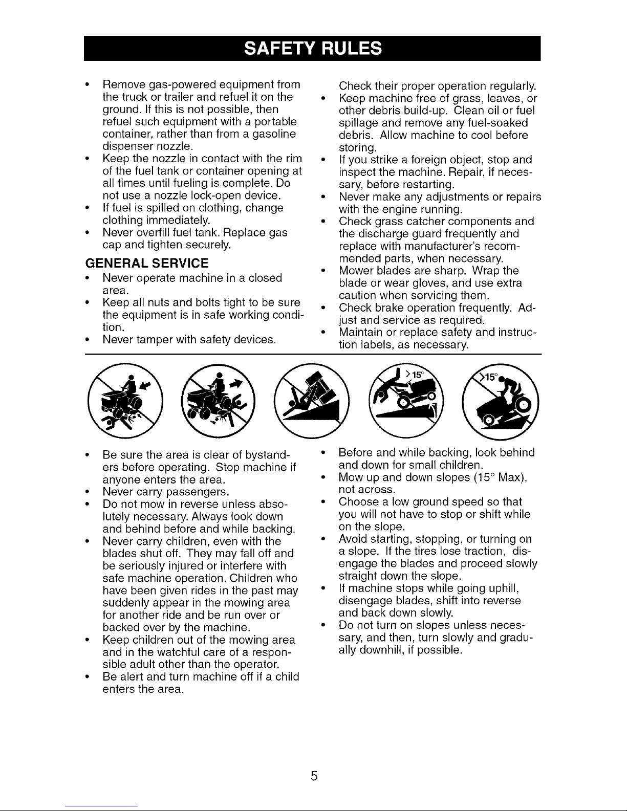
• Mow up and down slopes (15 ° Max),
not across.
• Choose a low ground speed so that
you will not have to stop or shift while
on the slope.
• Avoid starting, stopping, or turning on
a slope. If the tires lose traction, dis-
engage the blades and proceed slowly
straight down the slope.
• If machine stops while going uphill,
disengage blades, shift into reverse
and back down slowly.
• Do not turn on slopes unless neces-
sary, and then, turn slowly and gradu-
ally downhill, if possible.
5
PRODUCT SPECIFICATIONS
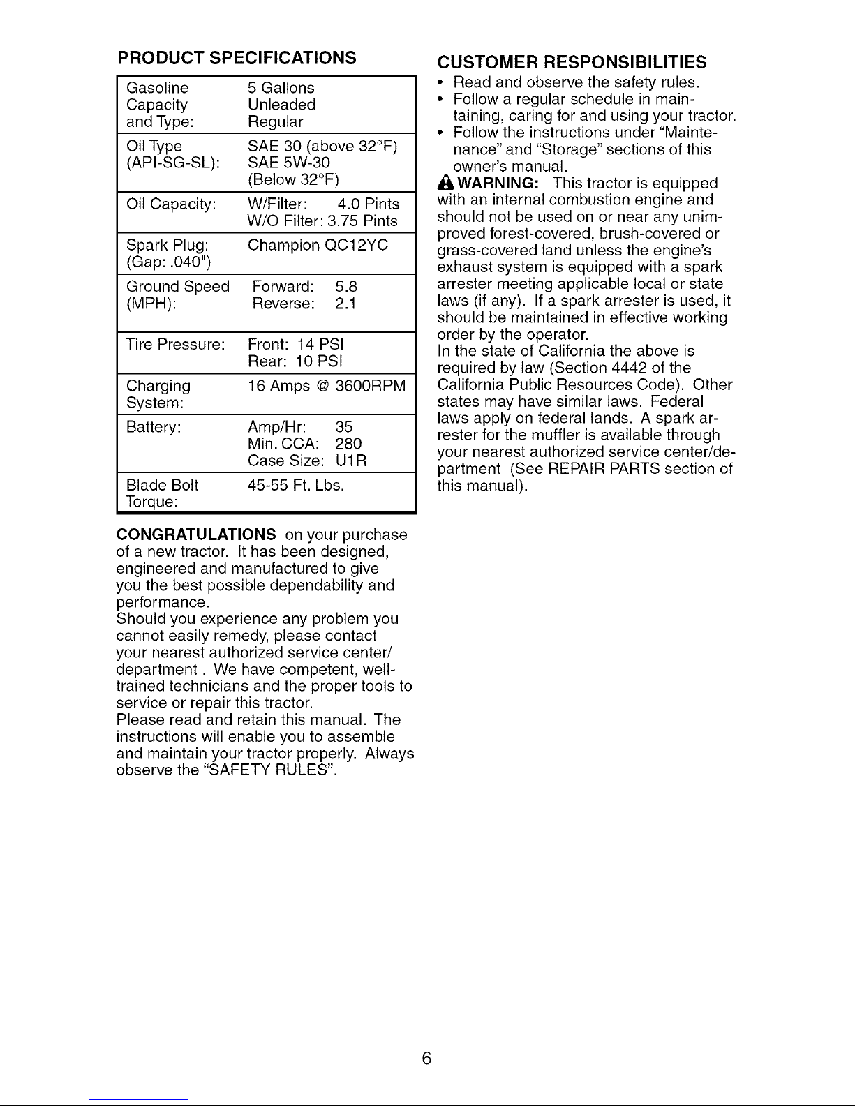
Gasoline 5 Gallons
Capacity Unleaded
and Type: Regular
Oil Type SAE 30 (above 32°F)
(API-SG-SL): SAE 5W-30
(Below 32°F)
Oil Capacity: W/Filter: 4.0 Pints
W/O Filter: 3.75 Pints
Spark Plug: Champion QC12YC
(Gap: .040")
Ground Speed Forward: 5.8
(MPH): Reverse: 2.1
Tire Pressure: Front: 14 PSI
Rear: 10 PSI
Charging 16 Amps @ 3600RPM
System:
Battery: Amp/Hr: 35
Min. CCA: 280
Case Size: U1R
Blade Bolt 45-55 Ft. Lbs.
Torque:
CUSTOMER RESPONSIBILITIES
• Read and observe the safety rules.
• Follow a regular schedule in main-
taining, caring for and using your tractor.
• Follow the instructions under "Mainte-
nance" and "Storage" sections of this
owner's manual.
,_WARNING: This tractor is equipped
with an internal combustion engine and
should not be used on or near any unim-
proved forest-covered, brush-covered or
grass-covered land unless the engine's
exhaust system is equipped with a spark
arrester meeting applicable local or state
laws (if any). If a spark arrester is used, it
should be maintained in effective working
order by the operator.
In the state of California the above is
required by law (Section 4442 of the
California Public Resources Code). Other
states may have similar laws. Federal
laws apply on federal lands. A spark ar-
rester for the muffler is available through
your nearest authorized service center/de-
partment (See REPAIR PARTS section of
this manual).
CONGRATULATIONS on your purchase
of a new tractor. It has been designed,
engineered and manufactured to give
you the best possible dependability and
performance.
Should you experience any problem you
cannot easily remedy, please contact
your nearest authorized service center/
department. We have competent, well-
trained technicians and the proper tools to
service or repair this tractor.
Please read and retain this manual. The
instructions will enable you to assemble
and maintain your tractor properly. Always
observe the "SAFETY RULES".
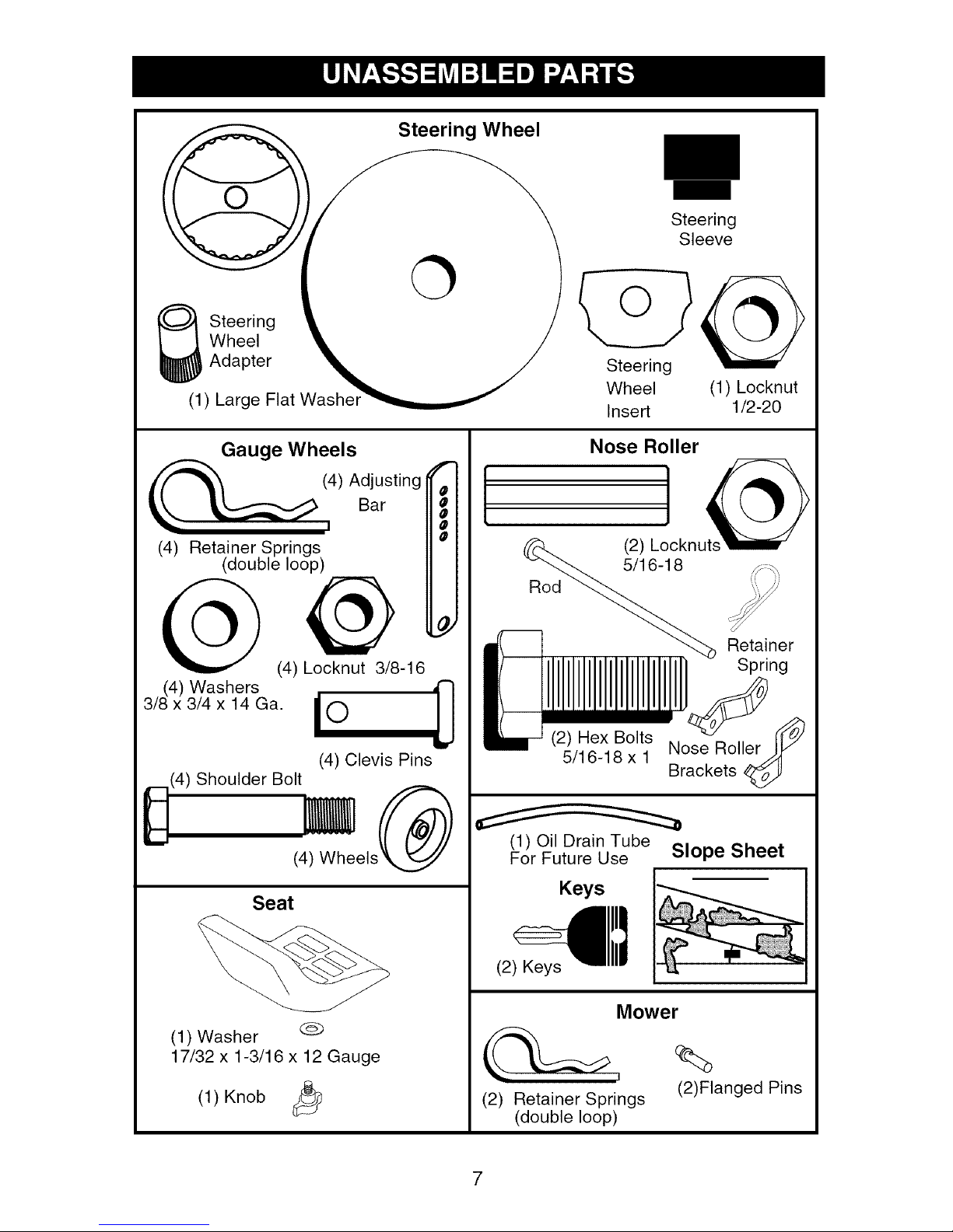
Wheel
_ teering
Adapter
(1) Large Flat
Steering Wheel
Steering
Sleeve
O
Steering
Wheel (1) Locknut
Insert 1/2-20
Gauge Wheels
(i) Adjusting
(4) Retainer Springs
(double loop)
@
(4) Locknut 3/8-16
(4) Washers
3/8 x 3/4 x 14 Ga. _ O
!
(4) Clevis Pins
Shoulder Bolt
(4)
(4) Wheels
Seat
Bar
Nose Roller
f
1
0
R_ Retainer
(2) Hex Bolts
5/16-18 x 1
(1) Oil Drain Tube
For Future Use Slope Sheet
Keys
(2) LJcknuts_
(1) Washer @
17/32 x 1-3/16 x 12 Gauge
(1) Knob
(2) Keys
(2) Retainer Springs
(double loop)
7
Mower
%
(2)Flanged Pins
Your new tractor has been assembled at the factory with the exception of those parts left
unassembled for shipping purposes. To ensure safe and proper operation of your tractor
all parts and hardware you assemble must be tightened securely. Use the correct tools
as necessary to insure proper tightness. Review the video cassette before you begin.
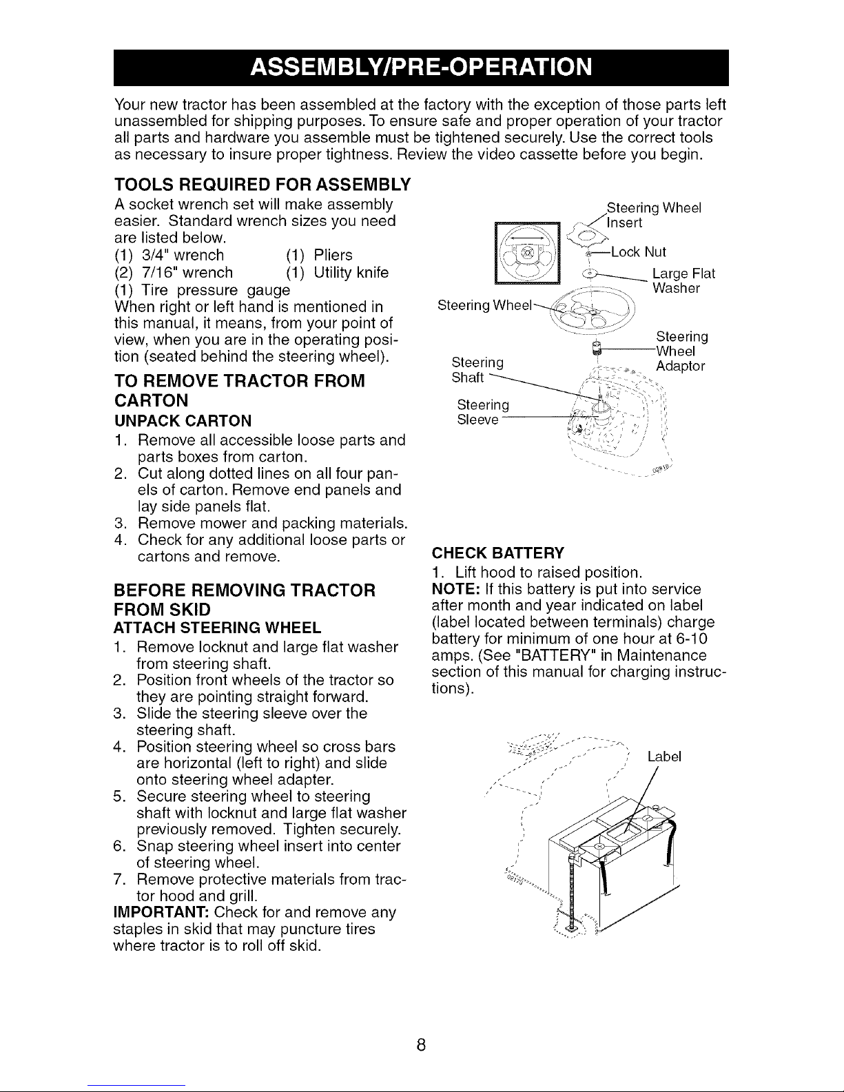
TOOLS REQUIRED FOR ASSEMBLY
A socket wrench set will make assembly
Steering Wheel
easier. Standard wrench sizes you need
are listed below.
(1) 3/4" wrench (1) Pliers
(2) 7/16" wrench (1) Utility knife
(1) Tire pressure gauge
When right or left hand is mentioned in
Steering
this manual, it means, from your point of
view, when you are in the operating posi-
tion (seated behind the steering wheel).
Steering
TO REMOVE TRACTOR FROM
CARTON
UNPACK CARTON
Steering
Sleeve
1. Remove all accessible loose parts and
parts boxes from carton.
2. Cut along dotted lines on all four pan-
els of carton. Remove end panels and
lay side panels flat.
3. Remove mower and packing materials.
4. Check for any additional loose parts or
cartons and remove.
CHECK BATTERY
1. Lift hood to raised position.
BEFORE REMOVING TRACTOR
FROM SKID
ATTACH STEERING WHEEL
1. Remove Iocknut and large flat washer
from steering shaft.
2. Position front wheels of the tractor so
they are pointing straight forward.
NOTE: If this battery is put into service
after month and year indicated on label
(label located between terminals) charge
battery for minimum of one hour at 6-10
amps. (See "BATTERY" in Maintenance
section of this manual for charging instruc-
tions).
3. Slide the steering sleeve over the
steering shaft.
z''C'/
4. Position steering wheel so cross bars
are horizontal (left to right) and slide
,,- , , Label
onto steering wheel adapter.
5. Secure steering wheel to steering
shaft with Iocknut and large flat washer
previously removed. Tighten securely.
6. Snap steering wheel insert into center
of steering wheel.
7. Remove protective materials from trac-
tor hood and grill.
IMPORTANT: Check for and remove any
staples in skid that may puncture tires
where tractor is to roll off skid.
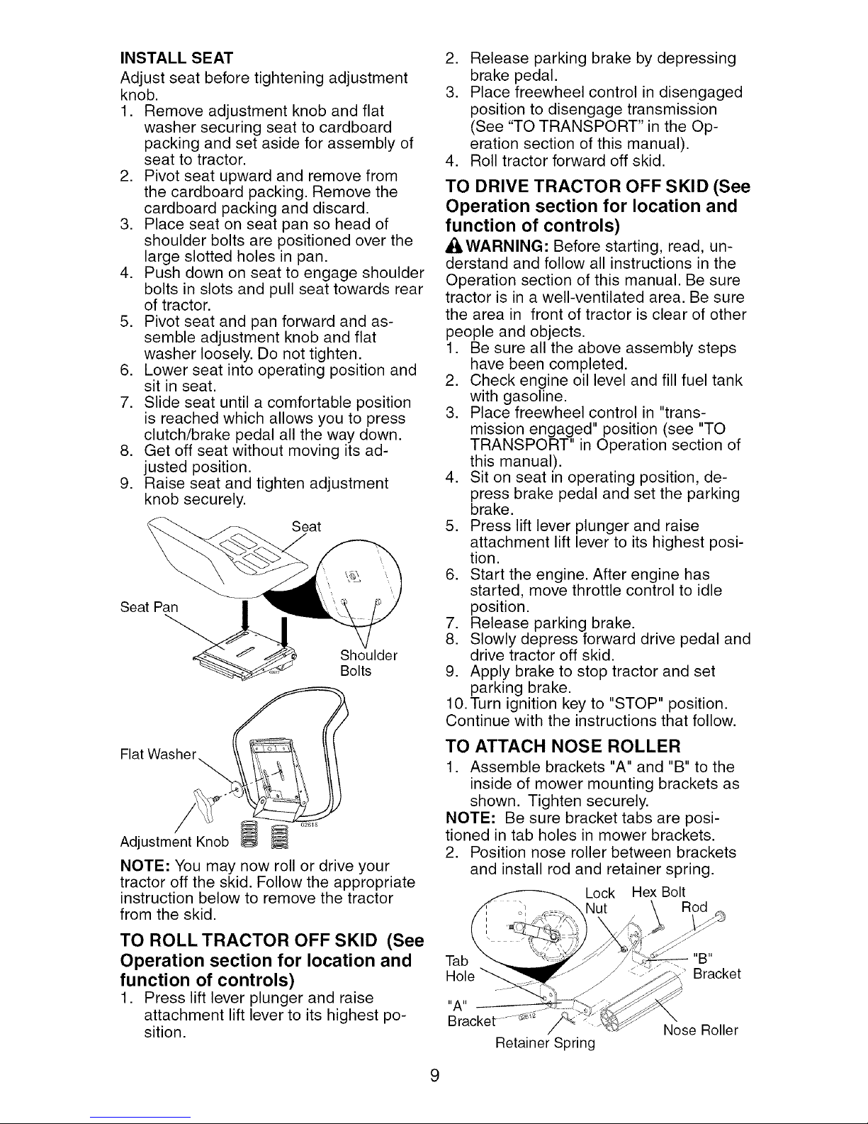
INSTALL SEAT
Adjust seat before tightening adjustment
knob.
1. Remove adjustment knob and flat
washer securing seat to cardboard
packing and set aside for assembly of
seat to tractor.
2. Pivot seat upward and remove from
the cardboard packing. Remove the
cardboard packing and discard.
3. Place seat on seat pan so head of
shoulder bolts are positioned over the
large slotted holes in pan.
4. Push down on seat to engage shoulder
bolts in slots and pull seat towards rear
of tractor.
5. Pivot seat and pan forward and as-
semble adjustment knob and flat
washer loosely. Do not tighten.
6. Lower seat into operating position and
sit in seat.
7. Slide seat until a comfortable position
is reached which allows you to press
clutch/brake pedal all the way down.
8. Get off seat without moving its ad-
justed position.
9. Raise seat and tighten adjustment
knob securely.
Seat
Seat Pan
Shoulder
Bolts
2. Release parking brake by depressing
brake pedal.
3. Place freewheel control in disengaged
position to disengage transmission
(See "TO TRANSPORT" in the Op-
eration section of this manual).
4. Roll tractor forward off skid.
TO DRIVE TRACTOR OFF SKID (See
Operation section for location and
function of controls)
Af:_WARNING: Before starting, read, un-
derstand and follow all instructions in the
Operation section of this manual. Be sure
tractor is in a well-ventilated area. Be sure
the area in front of tractor is clear of other
people and objects.
1. Be sure all the above assembly steps
have been completed.
2. Check engine oil level and fill fuel tank
with gasoline.
3. Place freewheel control in "trans-
mission engaged" position (see "TO
TRANSPORT" in Operation section of
this manual).
4. Sit on seat in operating position, de-
press brake pedal and set the parking
brake.
5. Press lift lever plunger and raise
attachment lift lever to its highest posi-
tion.
6. Start the engine. After engine has
started, move throttle control to idle
position.
7. Release parking brake.
8. Slowly depress forward drive pedal and
drive tractor off skid.
9. Apply brake to stop tractor and set
parking brake.
10. Turn ignition key to "STOP" position.
Continue with the instructions that follow.
Flat Washer
Adjustment Knob
NOTE: You may now roll or drive your
tractor off the skid. Follow the appropriate
instruction below to remove the tractor
from the skid.
TO ROLL TRACTOR OFF SKID (See
Operation section for location and
function of controls)
1. Press lift lever plunger and raise
attachment lift lever to its highest po-
sition.
TO ATTACH NOSE ROLLER
1. Assemble brackets "A" and "B" to the
inside of mower mounting brackets as
shown. Tighten securely.
NOTE: Be sure bracket tabs are posi-
tioned in tab holes in mower brackets.
2. Position nose roller between brackets
and install rod and retainer spring.
Lock Hex Bolt
Nut Rod
Tab "B"
"A"
Bracket ......._
Retainer Spring
Nose Roller
9
Bracket
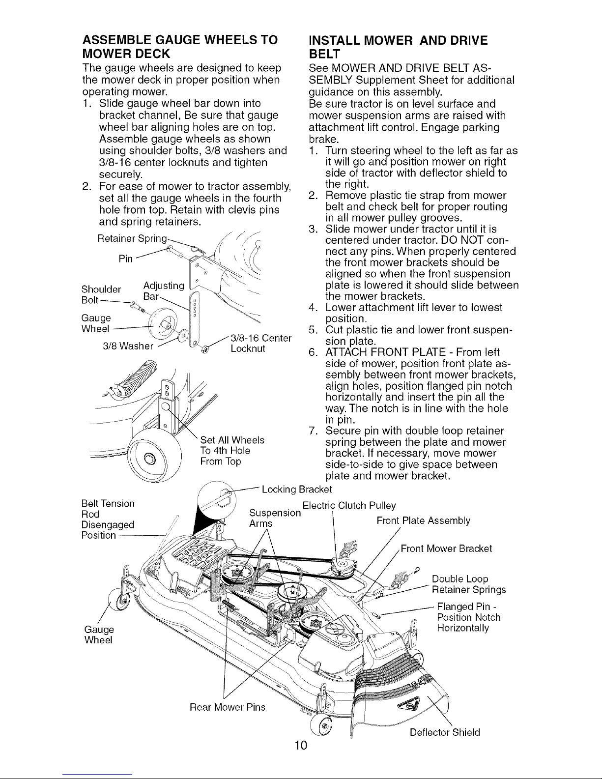
ASSEMBLE GAUGE WHEELS TO
MOWER DECK
The gauge wheels are designed to keep
the mower deck in proper position when
operating mower.
1. Slide gauge wheel bar down into
bracket channel, Be sure that gauge
wheel bar aligning holes are on top.
Assemble gauge wheels as shown
using shoulder bolts, 3/8 washers and
3/8-16 center Iocknuts and tighten
securely.
2. For ease of mower to tractor assembly,
set all the gauge wheels in the fourth
hole from top. Retain with clevis pins
and spring retainers.
RetainerS " f
Pin
Shoulder Adjusting
Bolt ____._.__qBar_ -_.
Gauge
Wheel
3/8Washer
Belt Tension
Rod
Disengaged
Position
_/3/8-16 Center
Locknut
_AII Wheels
To 4th Hole
From Top
INSTALL MOWER AND DRIVE
BELT
See MOWER AND DRIVE BELT AS-
SEMBLY Supplement Sheet for additional
guidance on this assembly.
Be sure tractor is on level surface and
mower suspension arms are raised with
attachment lift control. Engage parking
brake.
1. Turn steering wheel to the left as far as
it will go and position mower on right
side of tractor with deflector shield to
the right.
2. Remove plastic tie strap from mower
belt and check belt for proper routing
in all mower pulley grooves.
3. Slide mower under tractor until it is
centered under tractor. DO NOT con-
nect any pins. When properly centered
the front mower brackets should be
aligned so when the front suspension
plate is lowered it should slide between
the mower brackets.
4. Lower attachment lift lever to lowest
position.
5. Cut plastic tie and lower front suspen-
sion plate.
6. ATTACH FRONT PLATE - From left
side of mower, position front plate as-
sembly between front mower brackets,
align holes, position flanged pin notch
horizontally and insert the pin all the
way. The notch is in line with the hole
in pin.
7. Secure pin with double loop retainer
spring between the plate and mower
bracket. If necessary, move mower
side-to-side to give space between
plate and mower bracket.
g Bracket
Electric Clutch Pulley
Front Plate Assembly
Mower Bracket
Gauge
Wheel
Rear Mower Pins
Double Loop
prings
Flanged Pin -
Position Notch
Horizontally
Deflector Shield
10
8. Go to right hand side of mower and
insert pin and retainer spring in the
same manner.
9. CONNECT REAR PINS - Connect
right hand side first. Pull out and hold
the spring loaded pin, align hole in
suspension arm and release pin. Be
sure pin returns to fully seated position
and is attached to the suspension arm.
10. Go to left side of mower and connect
rear pin in the same manner.
11. Disengage belt tension rod.
12. From right side of tractor, install belt
onto engine clutch pulley.
IMPORTANT: Check belt for proper rout-
ing in all mower pulley grooves.
13. Engage belt tension rod on locking
bracket.
_I, CAUTION: Belt tension rod is spring
loaded. Have a tight grip on rod and en-
gage slowly.
14. Raise attachment lift lever to highest
position.
15. Adjust gauge wheels before operating
mower as shown in the Operation sec-
tion of this manual.
CHECK TIRE PRESSURE
The tires on your tractor were overinflated
at the factory for shipping purposes. Cor-
rect tire pressure is important for best
cutting performance.
• Reduce tire pressure to PSI shown in
"PRODUCT SPECIFICATIONS" section
of this manual.
CHECK DECK LEVELNESS
For best cutting results, mower housing
should be properly leveled. See "TO LEV-
EL MOWER HOUSING" in the Service
and Adjustments section of this manual.
CHECK FOR PROPER POSITION
OF ALL BELTS
See the figures that are shown for replac-
ing motion and mower blade drive belts
in the Service and Adjustments section
of this manual. Verify that the belts are
routed correctly.
CHECK BRAKE SYSTEM
After you learn how to operate your trac-
tor, check to see that the brake is properly
adjusted. See "TO ADJUST BRAKE" in
the Service and Adjustments section of
this manual.
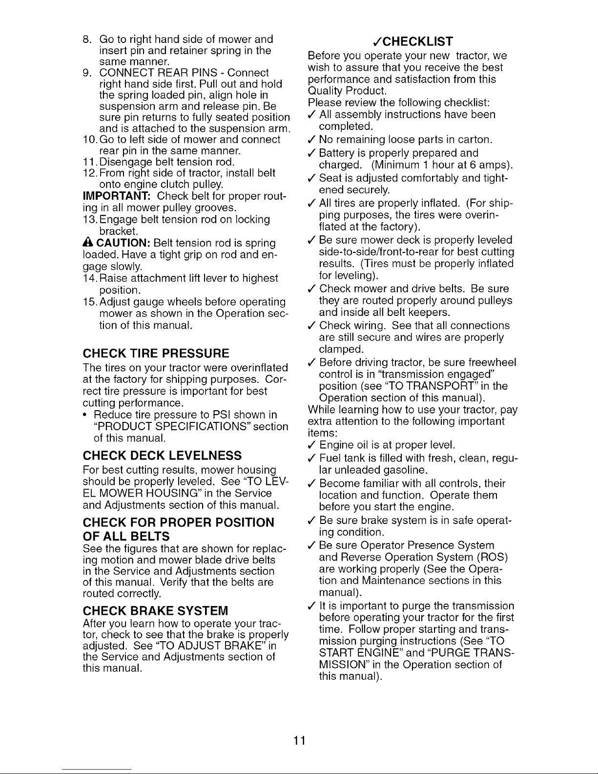
,/CHECKLIST
Before you operate your new tractor, we
wish to assure that you receive the best
performance and satisfaction from this
Quality Product.
Please review the following checklist:
,/All assembly instructions have been
completed.
,/No remaining loose parts in carton.
,/Battery is properly prepared and
charged. (Minimum 1 hour at 6 amps).
,/Seat is adjusted comfortably and tight-
ened securely.
,/All tires are properly inflated. (For ship-
ping purposes, the tires were overin-
flated at the factory).
,/Be sure mower deck is properly leveled
side-to-side/front-to-rear for best cutting
results. (Tires must be properly inflated
for leveling).
,/Check mower and drive belts. Be sure
they are routed properly around pulleys
and inside all belt keepers.
,/Check wiring. See that all connections
are still secure and wires are properly
clamped.
,/Before driving tractor, be sure freewheel
control is in "transmission engaged"
position (see "TO TRANSPORT" in the
Operation section of this manual).
While learning how to use your tractor, pay
extra attention to the following important
items:
,/Engine oil is at proper level.
,/Fuel tank is filled with fresh, clean, regu-
lar unleaded gasoline.
,/Become familiar with all controls, their
location and function. Operate them
before you start the engine.
,/Be sure brake system is in safe operat-
ing condition.
,/Be sure Operator Presence System
and Reverse Operation System (ROS)
are working properly (See the Opera-
tion and Maintenance sections in this
manual).
,/It is important to purge the transmission
before operating your tractor for the first
time. Follow proper starting and trans-
mission purging instructions (See "TO
START ENGINE" and "PURGE TRANS-
MISSION" in the Operation section of
this manual).
11
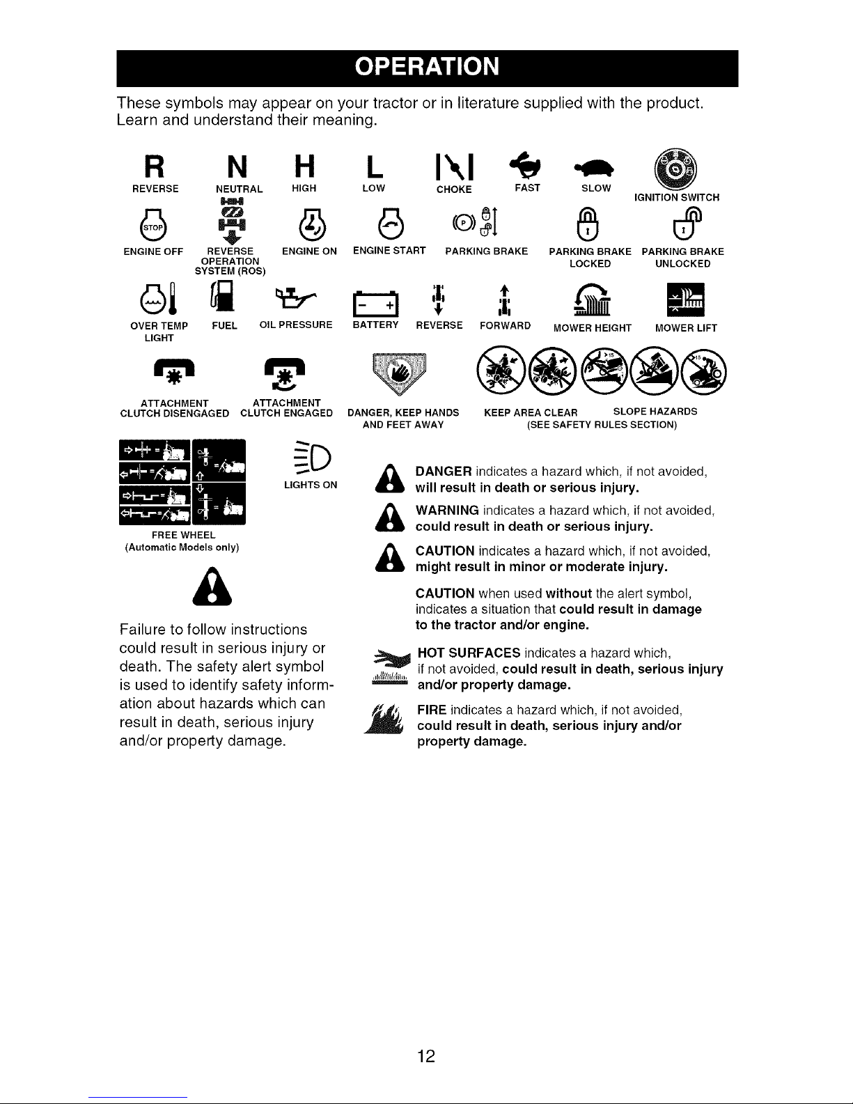
These symbols may appear on your tractor or in literature supplied with the product.
Learn and understand their meaning.
R N H L I\1
REVERSE NEUTRAL HIGH LOW CHOKE FAST
SLOW
IGNITION SWITCH
G 45 o, I
ENGINE OFF REVERSE ENGINE ON ENGINE START PARKING BRAKE
OPERATION
SYSTEM (ROS)
t
oi
OVER TEMP
LIGHT
FUEL OIL PRESSURE BATTERY REVERSE
FORWARD MOWER HEIGHT MOWER LIFT
PARKING BRAKE PARKING BRAKE
LOCKED UNLOCKED
®@@@@
ATTACHMENT ATTACHMENT
CLUTCH DISENGAGED CLUTCH ENGAGED
LIGHTS ON
FREE WHEEL
(Automatic Models only)
DANGER, KEEP HANDS
AND FEET AWAY
DANGER indicates a hazard which, if not avoided,
&
will result in death or serious injury.
WARNING indicates a hazard which, if not avoided,
could result in death or serious injury.
CAUTION indicates a hazard which, if not avoided,
&
might result in minor or moderate injury.
KEEP AREA CLEAR SLOPE HAZARDS
(SEE SAFETY RULES SECTION)
&
Failure to follow instructions
could result in serious injury or
death. The safety alert symbol
is used to identify safety inform-
ation about hazards which can
result in death, serious injury
and/or property damage.
CAUTION when used without the alert symbol,
indicates a situation that could result in damage
to the tractor and/or engine.
HOT SURFACES indicates a hazard which,
if not avoided, could result in death, serious injury
and/or property damage.
FIRE indicates a hazard which, if not avoided,
could result in death, serious injury and/or
property damage.
12
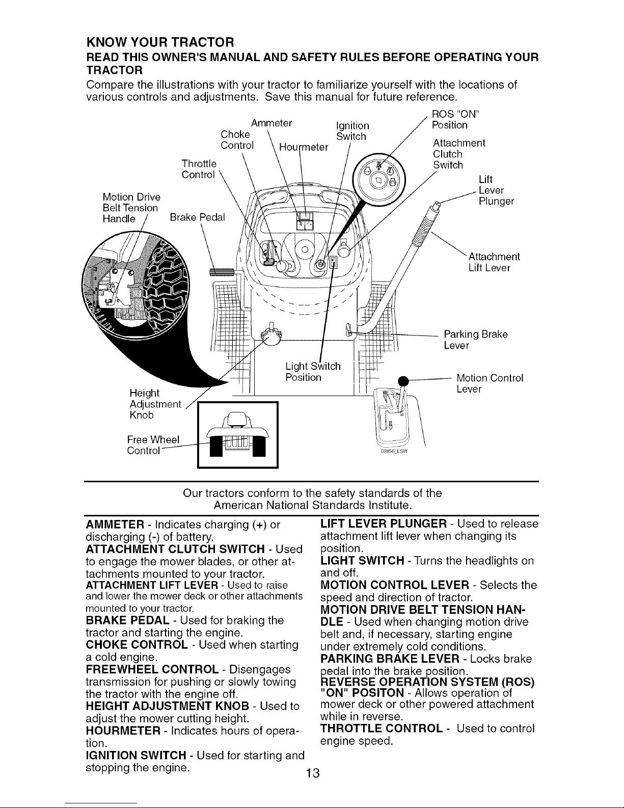
KNOW YOUR TRACTOR
READ THIS OWNER'S MANUAL AND SAFETY RULES BEFORE OPERATING YOUR
TRACTOR
Compare the illustrations with your tractor to familiarize yourself with the locations of
various controls and adjustments. Save this manual for future reference.
ROS "ON"
Position
Attachment
Clutch
Switch
Lift
Lever
Plunger
Motion Drive
Belt Tension
Handle
Ammeter Ignition
Choke Switch
Control Hourmeter
Throttle
Control
Brake Pedal
Attachment
Lift Lever
\ \
Parking Brake
Lever
Light
Position
Height
Adjustment
Knob
Free Wheel
Our tractors conform to the safety standards of the
American National Standards Institute.
AMMETER - Indicates charging (+) or
discharging (-) of battery.
ATTACHMENT CLUTCH SWITCH - Used
to engage the mower blades, or other at-
tachments mounted to your tractor.
ATTACHMENT LIFT LEVER - Used to raise
and lower the mower deck or other attachments
mounted to your tractor.
BRAKE PEDAL - Used for braking the
tractor and starting the engine.
CHOKE CONTROL - Used when starting
a cold engine.
FREEWHEEL CONTROL - Disengages
transmission for pushing or slowly towing
the tractor with the engine off.
HEIGHT ADJUSTMENT KNOB - Used to
adjust the mower cutting height.
HOURMETER - Indicates hours of opera-
tion.
IGNITION SWITCH - Used for starting and
stopping the engine.
Motion Control
Lever
02856 LSW
LIFT LEVER PLUNGER - Used to release
attachment lift lever when changing its
position.
LIGHT SWITCH - Turns the headlights on
and off.
MOTION CONTROL LEVER - Selects the
speed and direction of tractor.
MOTION DRIVE BELT TENSION HAN-
DLE - Used when changing motion drive
belt and, if necessary, starting engine
under extremely cold conditions.
PARKING BRAKE LEVER - Locks brake
_dal into the brake position.
VERSE OPERATION SYSTEM (ROS)
"ON" POSlTON - Allows operation of
mower deck or other powered attachment
while in reverse.
THROTTLE CONTROL - Used to control
engine speed.
13
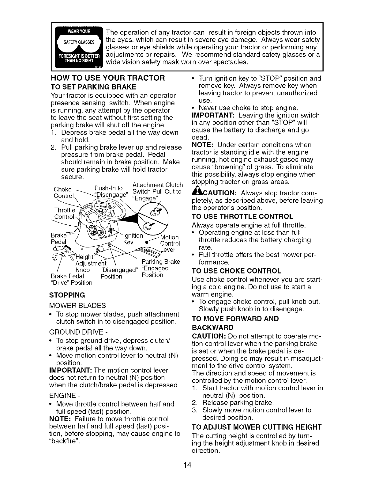
SAFETYGLASSES
The operation of any tractor can result in foreign objects thrown into
the eyes, which can result in severe eye damage. Always wear safety
glasses or eye shields while operating your tractor or performing any
adjustments or repairs. We recommend standard safety glasses or a
wide vision safety mask worn over spectacles.
HOW TO USE YOUR TRACTOR
TO SET PARKING BRAKE
Your tractor is equipped with an operator
presence sensing switch. When engine
is running, any attempt by the operator
to leave the seat without first setting the
parking brake will shut off the engine.
1. Depress brake pedal all the way down
and hold.
2. Pull parking brake lever up and release
pressure from brake pedal. Pedal
should remain in brake position. Make
sure parking brake will hold tractor
secu re.
Choke Push-In to
ngage" Switch Pull Out to
Throttle
Control,
Pedal Control
Adjustm_ Parking Brake
Knob "Disengaged" "Engaged"
Brake Pedal Position Position
"Drive" Position
STOPPING
MOWER BLADES -
• To stop mower blades, push attachment
clutch switch in to disengaged position.
GROUND DRIVE -
• To stop ground drive, depress clutch/
brake pedal all the way down.
• Move motion control lever to neutral (N)
position.
IMPORTANT: The motion control lever
does not return to neutral (N) position
when the clutch/brake pedal is depressed.
ENGINE -
• Move throttle control between half and
full speed (fast) position.
NOTE: Failure to move throttle control
between half and full speed (fast) posi-
tion, before stopping, may cause engine to
"backfire".
Attachment Clutch
Motion
• Turn ignition key to "STOP" position and
remove key. Always remove key when
leaving tractor to prevent unauthorized
use.
• Never use choke to stop engine.
IMPORTANT: Leaving the ignition switch
in any position other than "STOP" will
cause the battery to discharge and go
dead.
NOTE: Under certain conditions when
tractor is standing idle with the engine
running, hot engine exhaust gases may
cause "browning" of grass. To eliminate
this possibility, always stop engine when
stopping tractor on grass areas.
,_CAUTION: Always stop tractor com-
pletely, as described above, before leaving
the operator's position.
TO USE THROTTLE CONTROL
Always operate engine at full throttle.
• Operating engine at less than full
throttle reduces the battery charging
rate.
• Full throttle offers the best mower per-
formance.
TO USE CHOKE CONTROL
Use choke control whenever you are start-
ing a cold engine. Do not use to start a
warm engine.
• To engage choke control, pull knob out.
Slowly push knob in to disengage.
TO MOVE FORWARD AND
BACKWARD
CAUTION: Do not attempt to operate mo-
tion control lever when the parking brake
is set or when the brake pedal is de-
pressed. Doing so may result in misadjust-
ment to the drive control system.
The direction and speed of movement is
controlled by the motion control lever.
1. Start tractor with motion control lever in
neutral (N) position.
2. Release parking brake.
3. Slowly move motion control lever to
desired position.
TO ADJUST MOWER CUTTING HEIGHT
The cutting height is controlled by turn-
ing the height adjustment knob in desired
direction.
14
• Turn knob clockwise (F'_) to raise cut-
ting height.
• Turn knob counterclockwise ()_'_) to
lower cutting height.
The cutting height range is approximately
1-1/2" to 4-1/2". The heights are mea-
sured from the ground to the blade tip with
the engine not running.
These heights are approximate and may
vary depending upon soil conditions,
height of grass and types of grass being
mowed.
• The average lawn should be cut to
approximately 2-1/2 inches during the
cool season and to over 3 inches during
hot months. For healthier and better
looking lawns, mow often and after mod-
erate growth.
• For best cutting performance, grass over
6 inches in height should be mowed
twice. Make the first cut relatively high;
the second to desired height.
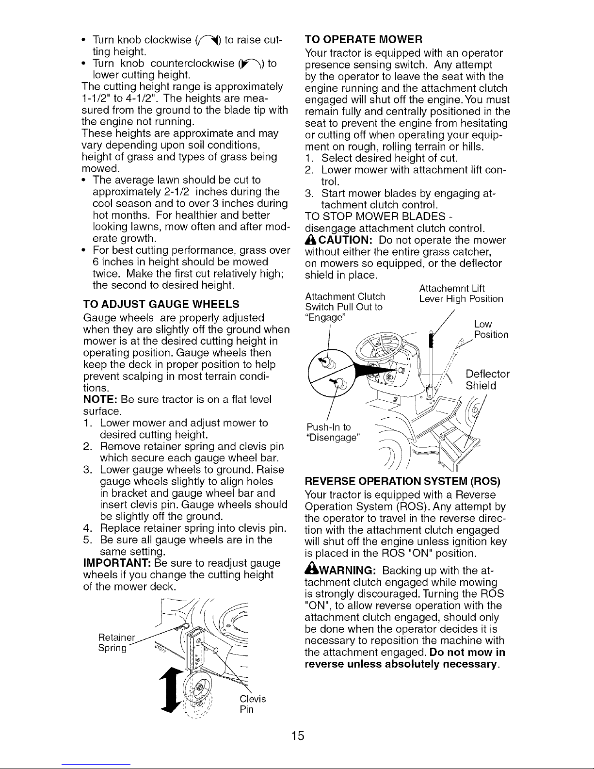
TO ADJUST GAUGE WHEELS
Gauge wheels are properly adjusted
when they are slightly off the ground when
mower is at the desired cutting height in
operating position. Gauge wheels then
keep the deck in proper position to help
prevent scalping in most terrain condi-
tions.
NOTE: Be sure tractor is on a flat level
surface.
1. Lower mower and adjust mower to
desired cutting height.
2. Remove retainer spring and clevis pin
which secure each gauge wheel bar.
3. Lower gauge wheels to ground. Raise
gauge wheels slightly to align holes
in bracket and gauge wheel bar and
insert clevis pin. Gauge wheels should
be slightly off the ground.
4. Replace retainer spring into clevis pin.
5. Be sure all gauge wheels are in the
same setting.
IMPORTANT: Be sure to readjust gauge
wheels if you change the cutting height
of the mower deck.
Retainer
Spring
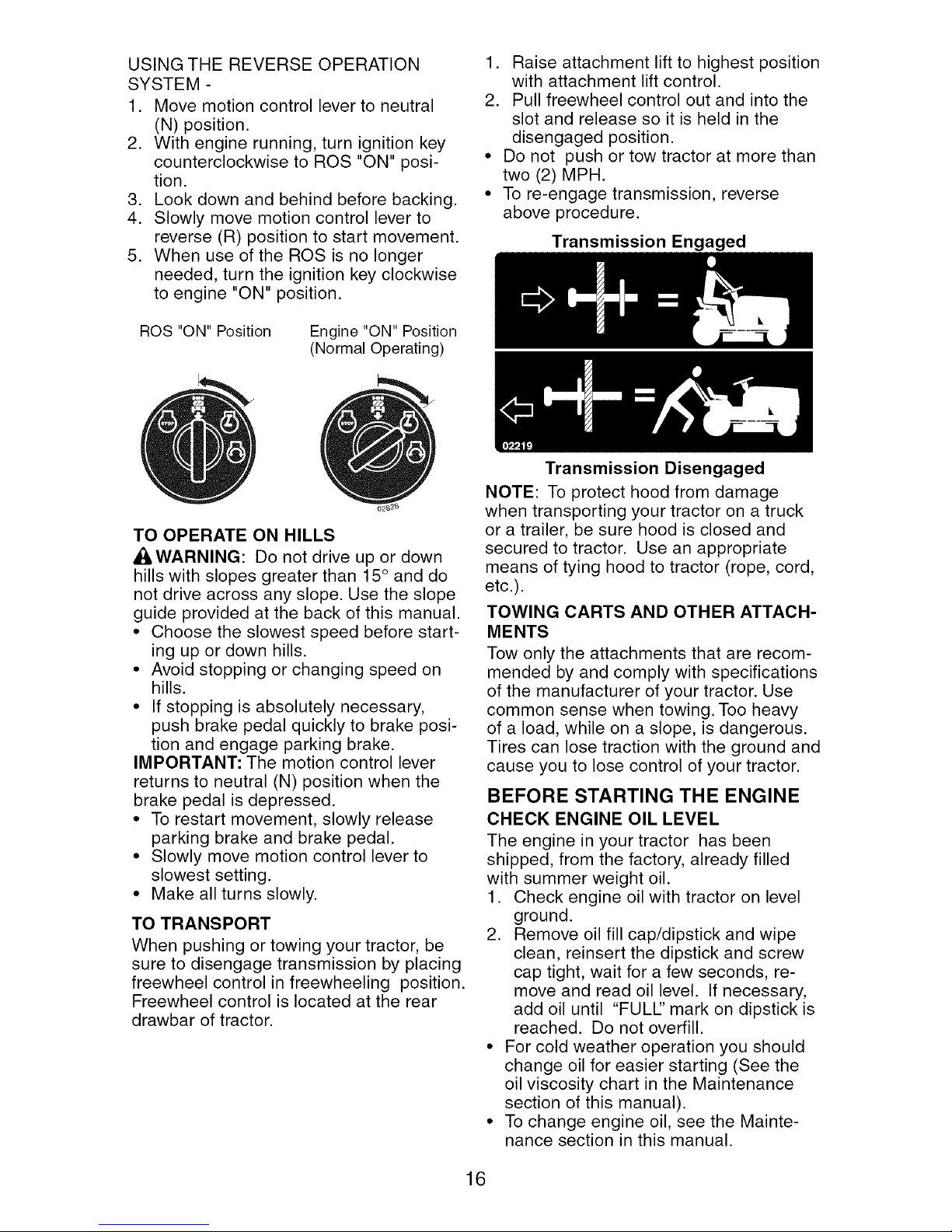
TO OPERATE MOWER
Your tractor is equipped with an operator
presence sensing switch. Any attempt
by the operator to leave the seat with the
engine running and the attachment clutch
engaged will shut off the engine. You must
remain fully and centrally positioned in the
seat to prevent the engine from hesitating
or cutting off when operating your equip-
ment on rough, rolling terrain or hills.
1. Select desired height of cut.
2. Lower mower with attachment lift con-
trol.
3. Start mower blades by engaging at-
tachment clutch control.
TO STOP MOWER BLADES -
disengage attachment clutch control.
A_ILCAUTION: Do not operate the mower
without either the entire grass catcher,
on mowers so equipped, or the deflector
shield in place.
Attachment Clutch
Switch Pull Out to
"Engage"
Attachemnt Lift
Lever High Position
Low
Position
,:_!J
Deflector
Shield
Push-In to
"Disengage"
REVERSE OPERATION SYSTEM (ROS)
Your tractor is equipped with a Reverse
Operation System (ROS). Any attempt by
the operator to travel in the reverse direc-
tion with the attachment clutch engaged
will shut off the engine unless ignition key
is placed in the ROS "ON" position.
_WARNING: Backing up with the at-
tachment clutch engaged while mowing
is strongly discouraged. Turning the ROS
"ON", to allow reverse operation with the
attachment clutch engaged, should only
be done when the operator decides it is
necessary to reposition the machine with
the attachment engaged. Do not mow in
reverse unless absolutely necessary.
Clevis
Pin
15
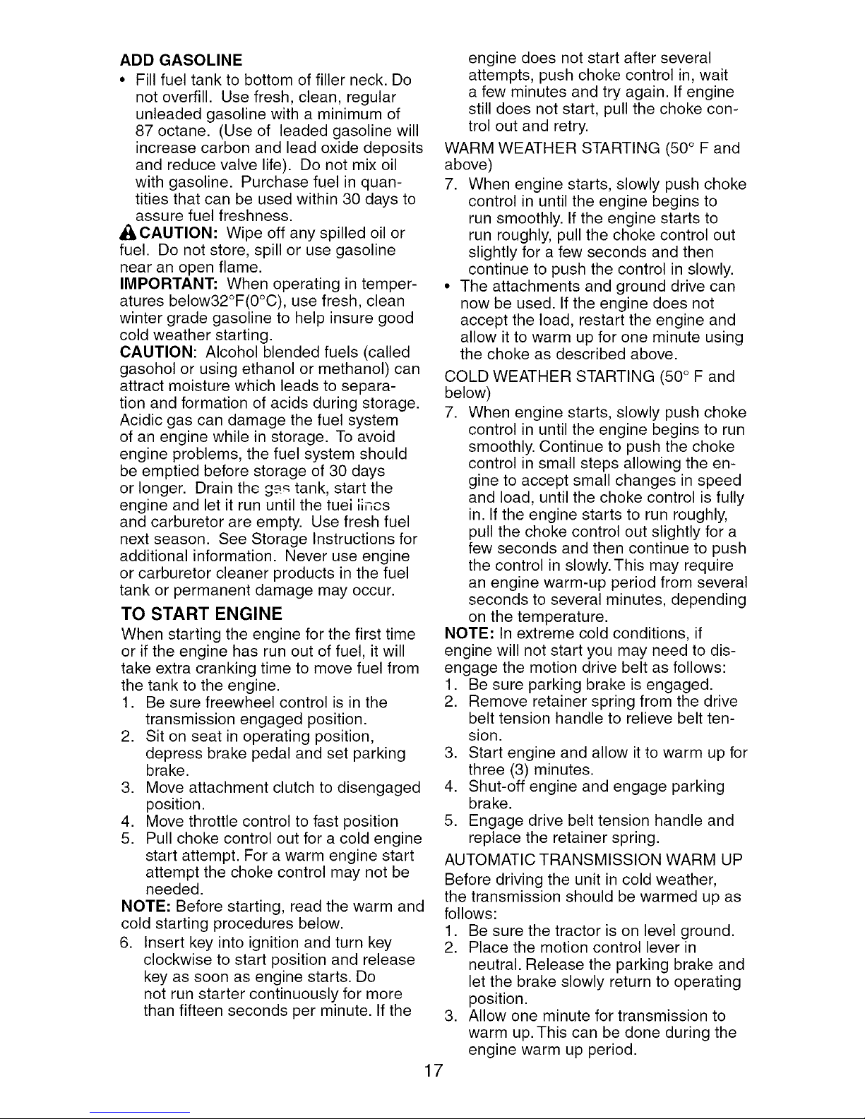
USING THE REVERSE OPERATION
SYSTEM -
1. Move motion control lever to neutral
(N) position.
2. With engine running, turn ignition key
counterclockwise to ROS "ON" posi-
tion.
3. Look down and behind before backing.
4. Slowly move motion control lever to
reverse (R) position to start movement.
5. When use of the ROS is no longer
needed, turn the ignition key clockwise
to engine "ON" position.
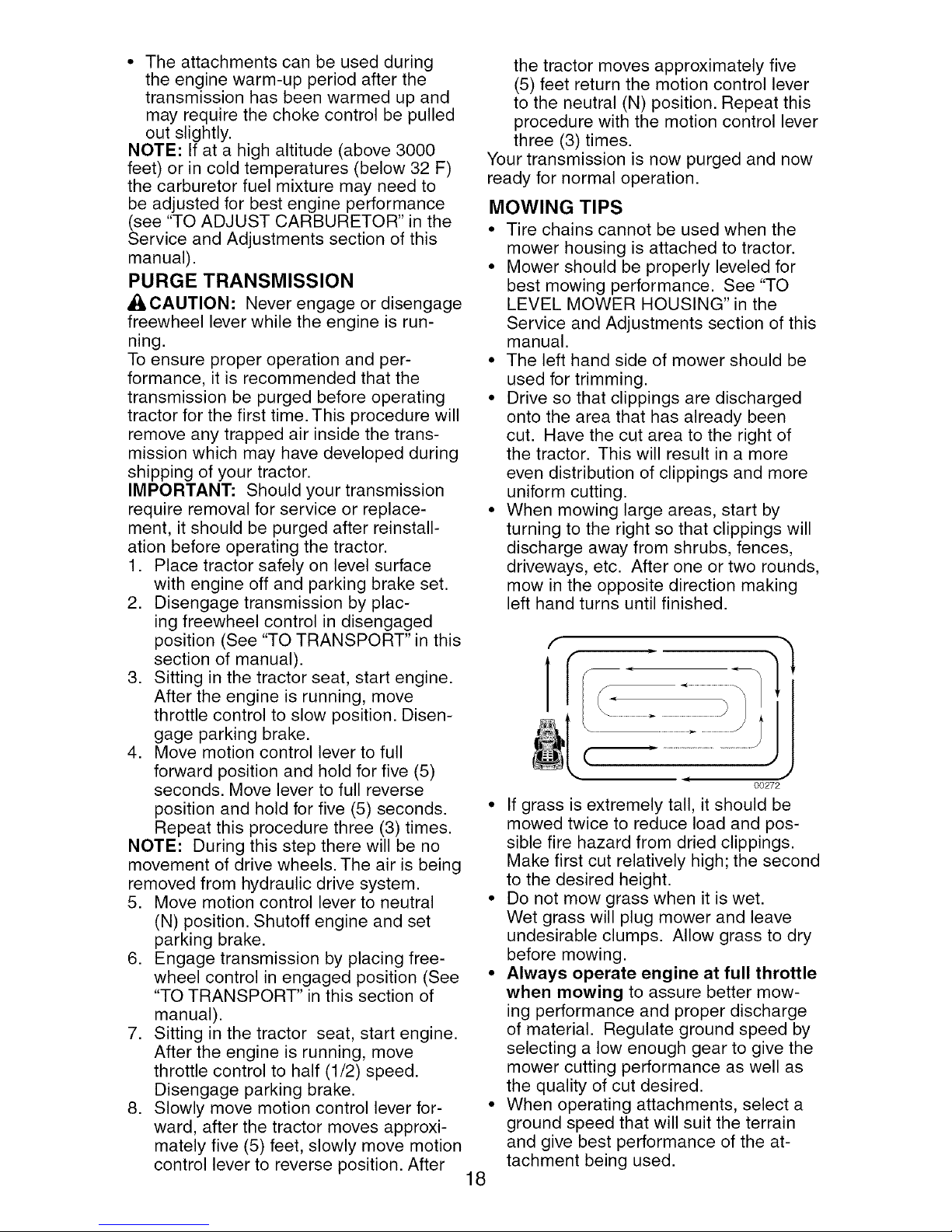
1. Raise attachment lift to highest position
with attachment lift control.
2. Pull freewheel control out and into the
slot and release so it is held in the
disengaged position.
• Do not push or tow tractor at more than
two (2) MPH.
• To re-engage transmission, reverse
above procedure.
Transmission Engaged
ROS "ON" Position
TO OPERATE ON HILLS
,AWARNING: Do not drive up or down
hills with slopes greater than 15° and do
not drive across any slope. Use the slope
guide provided at the back of this manual.
• Choose the slowest speed before start-
ing up or down hills.
• Avoid stopping or changing speed on
hills.
• If stopping is absolutely necessary,
push brake pedal quickly to brake posi-
tion and engage parking brake.
IMPORTANT: The motion control lever
returns to neutral (N) position when the
brake pedal is depressed.
• To restart movement, slowly release
parking brake and brake pedal.
• Slowly move motion control lever to
slowest setting.
• Make all turns slowly.
TO TRANSPORT
When pushing or towing your tractor, be
sure to disengage transmission by placing
freewheel control in freewheeling position.
Freewheel control is located at the rear
drawbar of tractor.
Engine "ON" Position
(Normal Operating)
Transmission Disengaged
NOTE: To protect hood from damage
when transporting your tractor on a truck
or a trailer, be sure hood is closed and
secured to tractor. Use an appropriate
means of tying hood to tractor (rope, cord,
etc.).
TOWING CARTS AND OTHER ATTACH-
MENTS
Tow only the attachments that are recom-
mended by and comply with specifications
of the manufacturer of your tractor. Use
common sense when towing. Too heavy
of a load, while on a slope, is dangerous.
Tires can lose traction with the ground and
cause you to lose control of your tractor.
BEFORE STARTING THE ENGINE
CHECK ENGINE OIL LEVEL
The engine in your tractor has been
shipped, from the factory, already filled
with summer weight oil.
1. Check engine oil with tractor on level
ground.
2. Remove oil fill cap/dipstick and wipe
clean, reinsert the dipstick and screw
cap tight, wait for a few seconds, re-
move and read oil level. If necessary,
add oil until "FULl" mark on dipstick is
reached. Do not overfill.
• For cold weather operation you should
change oil for easier starting (See the
oil viscosity chart in the Maintenance
section of this manual).
• To change engine oil, see the Mainte-
nance section in this manual.
16
ADD GASOLINE
• Fill fuel tank to bottom of filler neck. Do
not overfill. Use fresh, clean, regular
unleaded gasoline with a minimum of
87 octane. (Use of leaded gasoline will
increase carbon and lead oxide deposits
and reduce valve life). Do not mix oil
with gasoline. Purchase fuel in quan-
tities that can be used within 30 days to
assure fuel freshness.
_CAUTION: Wipe off any spilled oil or
fuel. Do not store, spill or use gasoline
near an open flame.
IMPORTANT: When operating in temper-
atures below32°F(0°C), use fresh, clean
winter grade gasoline to help insure good
cold weather starting.
CAUTION: Alcohol blended fuels (called
gasohol or using ethanol or methanol) can
attract moisture which leads to separa-
tion and formation of acids during storage.
Acidic gas can damage the fuel system
of an engine while in storage. To avoid
engine problems, the fuel system should
be emptied before storage of 30 days
or longer. Drain the g_ tank, start the
engine and let it run until the tuei lines
and carburetor are empty. Use fresh fuel
next season. See Storage Instructions for
additional information. Never use engine
or carburetor cleaner products in the fuel
tank or permanent damage may occur.
TO START ENGINE
When starting the engine for the first time
or if the engine has run out of fuel, it will
take extra cranking time to move fuel from
the tank to the engine.
1. Be sure freewheel control is in the
transmission engaged position.
2. Sit on seat in operating position,
depress brake pedal and set parking
brake.
3. Move attachment clutch to disengaged
position.
4. Move throttle control to fast position
5. Pull choke control out for a cold engine
start attempt. For a warm engine start
attempt the choke control may not be
needed.
NOTE: Before starting, read the warm and
cold starting procedures below.
6. Insert key into ignition and turn key
clockwise to start position and release
key as soon as engine starts. Do
not run starter continuously for more
than fifteen seconds per minute. If the
engine does not start after several
attempts, push choke control in, wait
a few minutes and try again. If engine
still does not start, pull the choke con-
trol out and retry.
WARM WEATHER STARTING (50 ° F and
above)
7. When engine starts, slowly push choke
control in until the engine begins to
run smoothly. If the engine starts to
run roughly, pull the choke control out
slightly for a few seconds and then
continue to push the control in slowly.
• The attachments and ground drive can
now be used. If the engine does not
accept the load, restart the engine and
allow it to warm up for one minute using
the choke as described above.
COLD WEATHER STARTING (50 ° F and
below)
7. When engine starts, slowly push choke
control in until the engine begins to run
smoothly. Continue to push the choke
control in small steps allowing the en-
gine to accept small changes in speed
and load, until the choke control is fully
in. If the engine starts to run roughly,
pull the choke control out slightly for a
few seconds and then continue to push
the control in slowly. This may require
an engine warm-up period from several
seconds to several minutes, depending
on the temperature.
NOTE: In extreme cold conditions, if
engine will not start you may need to dis-
engage the motion drive belt as follows:
1. Be sure parking brake is engaged.
2. Remove retainer spring from the drive
belt tension handle to relieve belt ten-
sion.
3. Start engine and allow it to warm up for
three (3) minutes.
4. Shut-off engine and engage parking
brake.
5. Engage drive belt tension handle and
replace the retainer spring.
AUTOMATIC TRANSMISSION WARM UP
Before driving the unit in cold weather,
the transmission should be warmed up as
follows:
1. Be sure the tractor is on level ground.
2. Place the motion control lever in
neutral. Release the parking brake and
let the brake slowly return to operating
position.
3. Allow one minute for transmission to
warm up. This can be done during the
engine warm up period.
17
• The attachments can be used during
the engine warm-up period after the
transmission has been warmed up and
may require the choke control be pulled
out slightly.
NOTE: If at a high altitude (above 3000
feet) or in cold temperatures (below 32 F)
the carburetor fuel mixture may need to
be adjusted for best engine performance
(see "TO ADJUST CARBURETOR" in the
Service and Adjustments section of this
manual).
PURGE TRANSMISSION
Ai_CAUTION: Never engage or disengage
freewheel lever while the engine is run-
ning.
To ensure proper operation and per-
formance, it is recommended that the
transmission be purged before operating
tractor for the first time. This procedure will
remove any trapped air inside the trans-
mission which may have developed during
shipping of your tractor.
IMPORTANT: Should your transmission
require removal for service or replace-
ment, it should be purged after reinstall-
ation before operating the tractor.
1. Place tractor safely on level surface
with engine off and parking brake set.
2. Disengage transmission by plac-
ing freewheel control in disengaged
position (See "TO TRANSPORT" in this
section of manual).
3. Sitting in the tractor seat, start engine.
After the engine is running, move
throttle control to slow position. Disen-
gage parking brake.
4. Move motion control lever to full
forward position and hold for five (5)
seconds. Move lever to full reverse
position and hold for five (5) seconds.
Repeat this procedure three (3) times.
NOTE: During this step there will be no
movement of drive wheels. The air is being
removed from hydraulic drive system.
5. Move motion control lever to neutral
(N) position. Shutoff engine and set
parking brake.
6. Engage transmission by placing free-
wheel control in engaged position (See
"TO TRANSPORT" in this section of
manual).
7. Sitting in the tractor seat, start engine.
After the engine is running, move
throttle control to half (1/2) speed.
Disengage parking brake.
8. Slowly move motion control lever for-
ward, after the tractor moves approxi-
mately five (5) feet, slowly move motion
control lever to reverse position. After
the tractor moves approximately five
(5) feet return the motion control lever
to the neutral (N) position. Repeat this
procedure with the motion control lever
three (3) times.
Your transmission is now purged and now
ready for normal operation.
MOWING TIPS
• Tire chains cannot be used when the
mower housing is attached to tractor.
• Mower should be properly leveled for
best mowing performance. See "TO
LEVEL MOWER HOUSING" in the
Service and Adjustments section of this
manual.
• The left hand side of mower should be
used for trimming.
• Drive so that clippings are discharged
onto the area that has already been
cut. Have the cut area to the right of
the tractor. This will result in a more
even distribution of clippings and more
uniform cutting.
• When mowing large areas, start by
turning to the right so that clippings will
discharge away from shrubs, fences,
driveways, etc. After one or two rounds,
mow in the opposite direction making
left hand turns until finished.
f
00272
If grass is extremely tall, it should be
mowed twice to reduce load and pos-
sible fire hazard from dried clippings.
Make first cut relatively high; the second
to the desired height.
Do not mow grass when it is wet.
Wet grass will plug mower and leave
undesirable clumps. Allow grass to dry
before mowing.
Always operate engine at full throttle
when mowing to assure better mow-
ing performance and proper discharge
of material. Regulate ground speed by
selecting a low enough gear to give the
mower cutting performance as well as
the quality of cut desired.
When operating attachments, select a
ground speed that will suit the terrain
and give best performance of the at-
tachment being used.
18
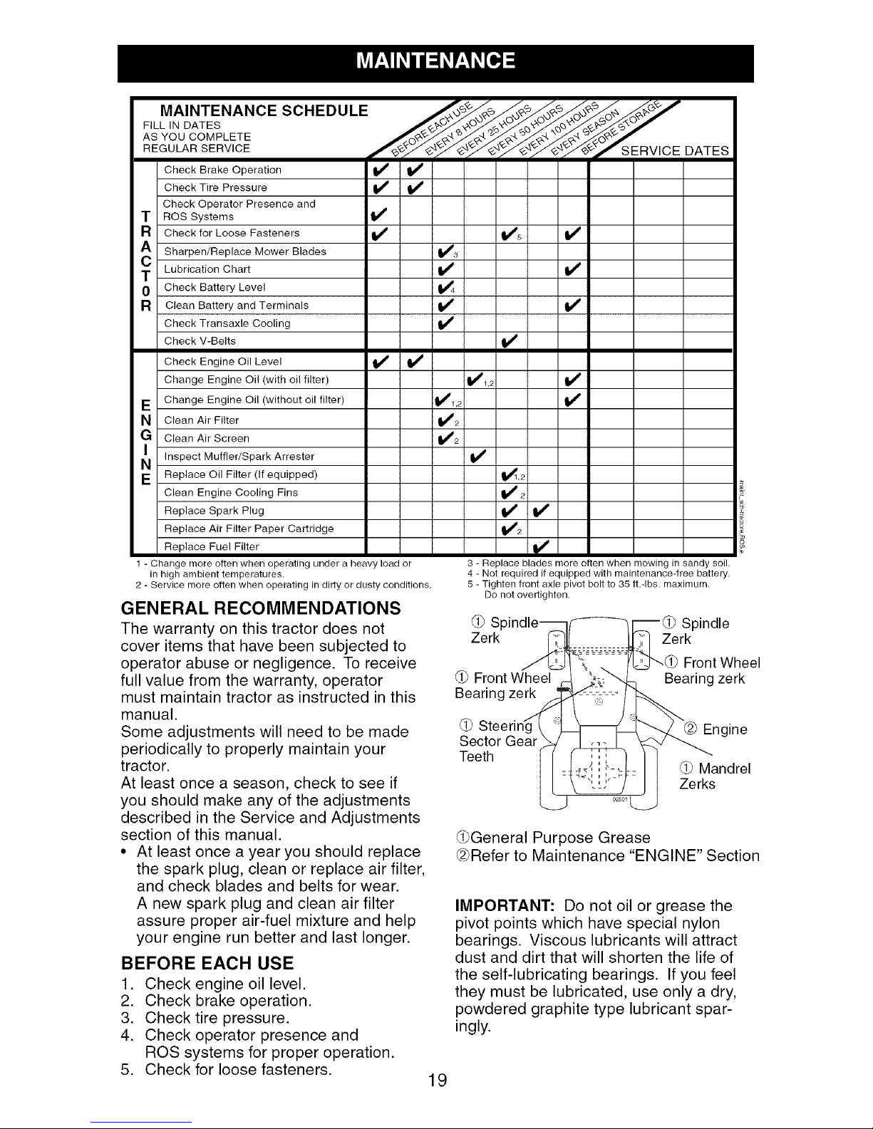
MAINTENANCE SCHEDULE ___ ,_o_o_ "_"
FILL IN DATES /__/,_-_._
AS¥ooCOMPLETE
REGOLARSERV,CE OATES
Check Operator Presence and
T ROS Systems 1_
R Check for Loose Fasteners I1_ ll_s If
A Sharpen/Replace Mower Blades 1_3
0 Check Battery Level
C Lubrication Chart _ tf
R Clean Battery and Terminals
Check Transaxle Cooling
Check V-Belts
Check Engine Oil Level I_ I_
Change Engine Oil (with oil filter) 1_1,2 If
E Change Engine Oil (without oil filter) _1,2
N Clean Air Filter 1_2
G Clean Air Screen _2
Inspect Muffler/Spark
E Replace Oil Filter (If equipped) _,2
Clean Engine Cooling Fins _ 2
Replace Spark Plug If I_
Replace Air Filter Paper Cartridge
Replace Fuel Filter _#'
1 - Change more often when operating under a heavy load or
in high ambient temperatures.
2 - Service more often when operating in dirty or dusty conditions.
Arrester
GENERAL RECOMMENDATIONS
The warranty on this tractor does not
cover items that have been subjected to
operator abuse or negligence. To receive
full value from the warranty, operator
must maintain tractor as instructed in this
manual.
Some adjustments will need to be made
periodically to properly maintain your
tractor.
At least once a season, check to see if
you should make any of the adjustments
described in the Service and Adjustments
section of this manual.
• At least once a year you should replace
the spark plug, clean or replace air filter,
and check blades and belts for wear.
A new spark plug and clean air filter
assure proper air-fuel mixture and help
your engine run better and last longer.
BEFORE EACH USE
1. Check engine oil level.
2. Check brake operation.
3. Check tire pressure.
4. Check operator presence and
ROS systems for proper operation.
5. Check for loose fasteners.
v'
3 - Replace blades more often when mowing in sandy soil.
4 - Not required if equipped with maintenance-free battery.
5 - Tighten front axle pivot bolt to 35 ft.-Ibs, maximum.
Do not overtighten.
SI Spindle
Zerk Zerk
Front Wheel
Front Wheel
Bearing zerk
Bearing zerk
./'i
Steenng I
Sector Gear
Teeth
Zerks
J
(l_bGeneralPurpose Grease
@Refer to Maintenance "ENGINE" Section
IMPORTANT: Do not oil or grease the
pivot points which have special nylon
bearings. Viscous lubricants will attract
dust and dirt that will shorten the life of
the self-lubricating bearings. If you feel
they must be lubricated, use only a dry,
powdered graphite type lubricant spar-
ingly.
19
Engine
Mandrel
TRACTOR
Always observe safety rules when per-
forming any maintenance.
BRAKE OPERATION
If tractor requires more than five (5) feet to
stop at highest speed in highest gear on a
level, dry concrete or paved surface, then
brake must be checked and adjusted. (See
"TO ADJUST BRAKE" in the Service and
Adjustments section of this manual).
TIRES
• Maintain proper air pressure in all tires
(See "PRODUCT SPECIFICATIONS"
section of this manual).
• Keep tires free of gasoline, oil, or insect
control chemicals which can harm rub-
ber.
• Avoid stumps, stones, deep ruts, sharp
objects and other hazards that may
cause tire damage.
NOTE: To seal tire punctures and prevent
flat tires due to slow leaks, tire sealant
may be purchased from your local parts
dealer. Tire sealant also prevents tire dry
rot and corrosion.
OPERATOR PRESENCE SYSTEM AND
REVERSE OPERATION SYSTEM (ROS)
Be sure operator presence and reverse
operation systems are working properly. If
your tractor does not function as de-
scribed, repair the problem immediately.
• The engine should not start unless the
brake pedal is fully depressed, and the
attachment clutch control is in the disen-
gaged position.
CHECK OPERATOR PRESENCE
SYSTEM
• When the engine is running, any at-
tempt by the operator to leave the seat
without first setting the parking brake
should shut off the engine.
• When the engine is running and the
attachment clutch is engaged, any at-
tempt by the operator to leave the seat
should shut off the engine.
• The attachment clutch should never op-
erate unless the operator is in the seat.
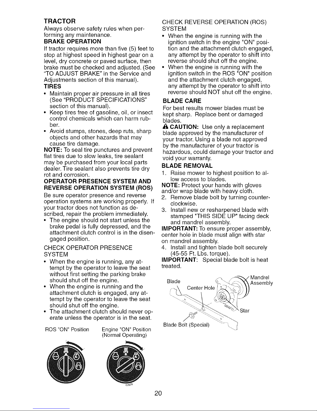
ROS "ON" Position
Engine "ON" Position
(Normal Operating)
CHECK REVERSE OPERATION (ROS)
SYSTEM
• When the engine is running with the
ignition switch in the engine "ON" posi-
tion and the attachment clutch engaged,
any attempt by the operator to shift into
reverse should shut off the engine.
• When the engine is running with the
ignition switch in the ROS "ON" position
and the attachment clutch engaged,
any attempt by the operator to shift into
reverse should NOT shut off the engine.
BLADE CARE
For best results mower blades must be
kept sharp. Replace bent or damaged
blades.
A CAUTION: Use only a replacement
blade approved by the manufacturer of
your tractor. Using a blade not approved
by the manufacturer of your tractor is
hazardous, could damage your tractor and
void your warranty.
BLADE REMOVAL
1. Raise mower to highest position to al-
low access to blades.
NOTE: Protect your hands with gloves
and/or wrap blade with heavy cloth.
2. Remove blade bolt by turning counter-
clockwise.
3. Install new or resharpened blade with
stamped "THIS SIDE UP" facing deck
and mandrel assembly.
IMPORTANT: To ensure proper assembly,
center hole in blade must align with star
on mandrel assembly.
4. Install and tighten blade bolt securely
(45-55 Ft. Lbs. torque).
IMPORTANT: Special blade bolt is heat
treated.
Blade
Center
Blade Bolt (Special)
Mandrel
Assembly
Star
20
TO SHARPEN BLADE
NOTE: We do not recommend sharp-
ening blade - but if you do, be sure the
blade is balanced.
Care should be taken to keep the blade
balanced. An unbalanced blade will cause
excessive vibration and eventual damage
to mower and engine.
• The blade can be sharpened with a file
or on a grinding wheel. Do not attempt
to sharpen while on the mower.
• To check blade balance, you will need a
5/8" diameter steel bolt, pin, or a cone
balancer. (When using a cone balancer,
follow the instructions supplied with
balancer.)
NOTE: Do not use a nail for balancing
blade. The lobes of the center hole may
appear to be centered, but are not.
• Slide blade on to an unthreaded portion
of the steel bolt or pin and hold the
bolt or pin parallel with the ground. If
blade is balanced, it should remain in a
horizontal position. If either end of the
blade moves downward, sharpen the
heavy end until the blade is balanced.
5/8" Bolt
or Pin
Center Hole
BATTERY
Your tractor has a battery charging system
which is sufficient for normal use. How-
ever, periodic charging of the battery with
an automotive charger will extend its life.
• Keep battery and terminals clean.
• Keep battery bolts tight.
• Keep small vent holes open.
• Recharge at 6-10 amperes for 1 hour.
NOTE: The original equipment battery on
your tractor is maintenance free. Do not
attempt to open or remove caps or covers.
Adding or checking level of electrolyte is
not necessary.
TO CLEAN BATTERY AND TERMINALS
Corrosion and dirt on the battery and
terminals can cause the battery to "leak"
power.
1. Remove terminal guard.
2. Disconnect BLACK battery cable first
then RED battery cable and remove
battery from tractor.
3. Rinse the battery with plain water and
dry.
4. Clean terminals and battery cable ends
with wire brush until bright.
5. Coat terminals with grease or petro-
leum jelly.
6. Reinstall battery (See "REPLACING
BATTERY" in the SERVICE AND AD-
JUSTMENTS section of this manual).
TRANSAXLE COOLING
The transmission fan and cooling fins
should be kept clean to assure proper
cooling.
Do not attempt to clean fan or transmis-
sion while engine is running or while the
transmission is hot. To prevent possible
damage to seals, do not use high pres-
sure water or steam to clean transaxle.
• Inspect cooling fan to be sure fan blades
are intact and clean.
• Inspect cooling fins for dirt, grass clip-
pings and other materials. To prevent
damage to seals, do not use com-
pressed air or high pressure sprayer to
clean cooling fins.
TRANSAXLE PUMP FLUID
The transaxle was sealed at the factory
and fluid maintenance is not required for
the life of the transaxle. Should the trans-
axle ever leak or require servicing, contact
a qualified service center.
V-BELTS
Check V-belts for deterioration and wear
after 100 hours of operation and replace
if necessary. The belts are not adjustable.
Replace belts if they begin to slip from
wear.
ENGINE
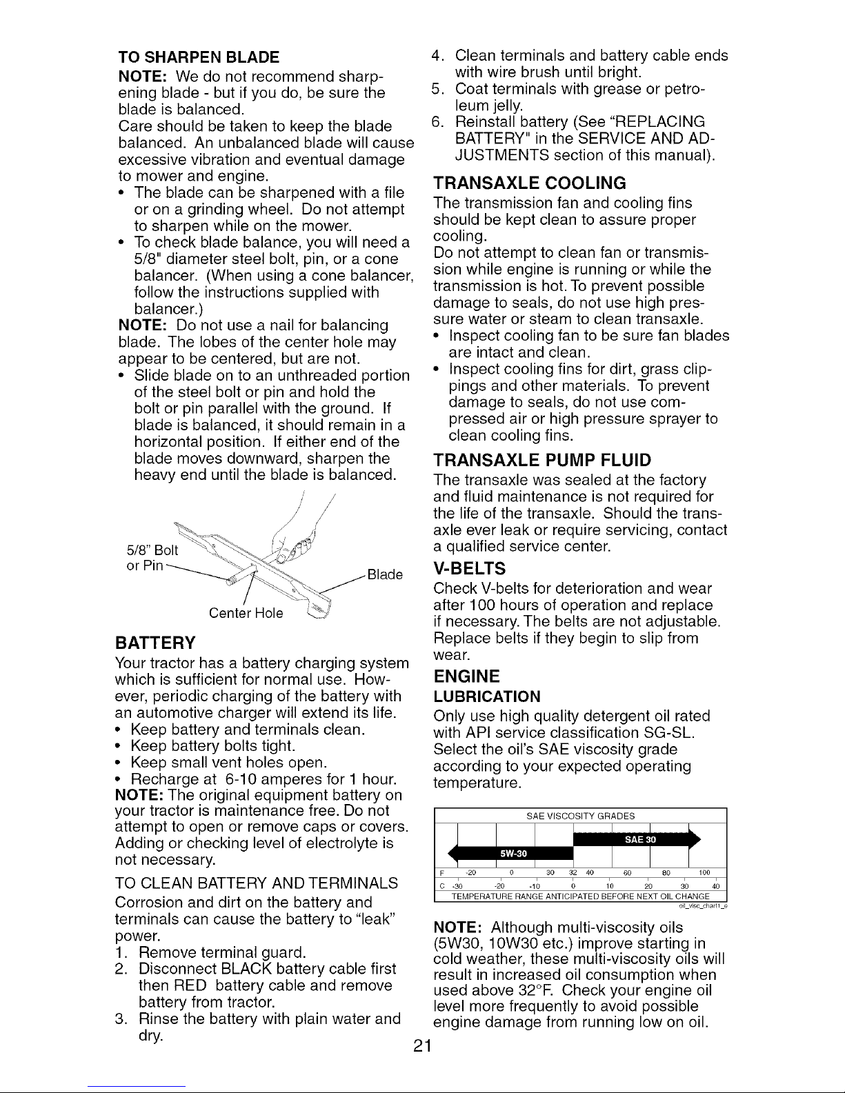
LUBRICATION
Only use high quality detergent oil rated
with API service classification SG-SL.
Select the oil's SAE viscosity grade
according to your expected operating
temperature.
SAE VISCOSITY GRADES
F -20 0 30 32 40 60 80 100
o -i0 -2; -1; ; 1'0 _o io 4o
TEMPERATURE RANGE ANTICIPATED BEFORE NEXT OIL CHANGE
NOTE: Although multi-viscosity oils
(5W30, 10W30 etc.) improve starting in
cold weather, these multi-viscosity oils will
result in increased oil consumption when
used above 32°E Check your engine oil
level more frequently to avoid possible
engine damage from running low on oil.
21
oi_ v_scchartl e
 Loading...