

Southern States SPGT25H48A Owner's Manual

For Parts Call K&T 606-678-9623 or 606-561-4983
MODEL NO. SPGT25H48A
25.0 HP 48 INCH
GARDEN TRACTOR
• Assembly
• Operation
• Maintenance
• Service and Adjustments
• Storage
• Troubleshooting
• Repair Parts
For Parts and Service, contact our authorized distributor:
call 1-800-849-1297 For Technical Assistance: call 1-800-829-5886
02716 Southern States
185478 Rev. 3 9.22.03 TR/MH
www.mymowerparts.com
PRINTED IN U.S.A.

For Parts Call K&T 606-678-9623 or 606-561-4983
TABLE OF CONTENTS
Warranty................................................ 2
Safety Rules .......................................... 3
Product Specifi cations........................... 6
Assembly/Pre-Operation ....................... 8
Operation............................................. 12
Maintenance ....................................... 19
Maintenance Schedule........................ 19
Service and Adjustments..................... 24
Storage................................................ 31
Troubleshooting ................................... 32
Repair Parts......................................... 36
WARRANTY
LIMITED WARRANTY
The Manufacturer warrants to the original consumer purchaser that this product as
manufactured is free from defects in materials and work man ship. For a period of two
(2) years from date of purchase by the original consumer purchaser, we will repair or
replace, at our option, without charge for parts or labor incurred in replacing parts, any
part which we fi nd to be defective due to materials or workmanship. This Warranty is
subject to the following limitations and exclusions.
1. This warranty does not apply to the engine, other than EHP manufactured transaxle/
transmission components, battery (except as noted below) or components parts
thereof. Please refer to the applicable manufacturer's warranty on these items.
2. Transportation charges for the movement of any power equipment unit or attachment
are the responsibility of the pur chaser. Transportation charges for any parts submitted for replacement under this warranty must be paid by the purchaser unless such
return is requested by Electrolux Home Products.
3. Battery Warranty: On products equipped with a Battery, we will replace, without
charge to you, any battery which we fi nd to be defective in manufacture, during the
fi rst ninety (90) days of ownership. After ninety (90) days, we will exchange the Battery, charging you 1/12 of the price of a new Battery for each full month from the date
of the original sale. Battery must be maintained in accordance with the instructions
furnished.
4. The Warranty period for any products used for rental or commercial purposes is
limited to 90 days from the date of original purchase.
5. This Warranty applies only to products which have been properly assembled, adjusted, operated, and main tained in ac cor dance with the instructions furnished. This
Warranty does not apply to any product which has been subjected to alteration, misuse, abuse, improper assembly or installation, delivery damage, or to normal wear of
the product.
6. Exclusions: Excluded from this Warranty are belts, blades, blade adapters, normal
wear, normal adjustments, stan dard hardware and normal maintenance.
7. In the event you have a claim under this Warranty, you must return the product to an
authorized service dealer.
Should you have any unanswered questions concerning this Warranty, please contact:
Electrolux Home Products, Inc.
Outdoor Products Customer Service Dept.
250 Bobby Jones Expressway
Augusta, GA 30909 USA
In Canada contact:
Electrolux Canada Corp.
7075 Ordan Drive
Mississauga, Ontario
L5T 1K6
giving the model number, serial number and date of purchase of your product and the
name and address of the authorized dealer from whom it was purchased.
THIS WARRANTY DOES NOT APPLY TO INCIDENTAL OR CONSEQUENTIAL
DAMAGES AND ANY IMPLIED WAR RAN TIES ARE LIMITED TO THE SAME TIME
PERIODS STATED HEREIN FOR OUR EXPRESSED WARRANTIES. Some areas do
not allow the limitation of consequential damages or limitations of how long an implied
Warranty may last, so the above limitations or exclusions may not apply to you. This
Warranty gives you specifi c legal rights, and you may have other rights which vary from
locale to locale.
This is a limited Warranty within the meaning of that term as defi ned in the MagnusonMoss Act of 1975.
2
www.mymowerparts.com

For Parts Call K&T 606-678-9623 or 606-561-4983
SAFETY RULES
IMPORTANT: This cutting machine is ca pa ble of amputating hands and feet and throw-
ing objects. Failure to observe the fol low ing safety instructions could result in serious
injury or death.
WARNING: In order to prevent accidental starting when setting up, trans port ing, ad just ing or making repairs,
always dis con nect spark plug wire and
place wire where it can not contact spark
plug.
WARNING: Do not coast down a hill in
neutral, you may lose control of the tractor.
WARNING: Tow only the attachments
that are rec om mend ed by and comply with
spec i fi ca tions of the man u fac tur er of your
tractor. Use common sense when towing.
Operate only at the lowest possible speed
when on a slope. Too heavy of a load,
while on a slope, is dan ger ous. Tires can
lose trac tion with the ground and cause
you to lose control of your tractor.
WARNING: Engine exhaust, some of its
constituents, and certain vehicle com po nents contain or emit chem i cals known to
the State of Cal i for nia to cause can cer and
birth defects or oth er re pro duc tive harm.
WARNING: Battery posts, terminals
and related accessories contain lead and
lead compounds, chemicals known to the
State of Cal i for nia to cause can cer and
birth defects or oth er re pro duc tive harm.
Wash hands after handling.
I. GENERAL OPERATION
• Read, understand, and follow all instruc-
tions in the manual and on the machine
before starting.
• Only allow responsible adults, who are
familiar with the in struc tions, to operate
the machine.
• Clear the area of objects such as rocks,
toys, wire, etc., which could be picked
up and thrown by the blade.
• Be sure the area is clear of other people
before mow ing. Stop machine if anyone
enters the area.
• Never carry passengers.
• Do not mow in reverse unless ab so -
lute ly necessary. Always look down and
behind before and while back ing.
• Be aware of the mower discharge direc-
tion and do not point it at anyone. Do
not operate the mower without either
the entire grass catcher or the guard in
place.
• Slow down before turning.
• Never leave a running machine unattended. Always turn off blades, set
parking brake, stop engine, and remove
keys before dismounting.
• Turn off blades when not mowing.
• Stop engine before removing grass
catcher or un clog ging chute.
• Mow only in daylight or good artifi cial
light.
• Do not operate the machine while under
the infl uence of alcohol or drugs.
• Watch for traffi c when operating near or
crossing road ways.
• Use extra care when loading or un load ing the machine into a trailer or
truck.
• Data indicates that operators, age 60
years and above, are involved in a large
percentage of riding mower-related injuries. These operators should evaluate
their ability to operate the riding mower
safely enough to protect them selves and
others from serious injury.
• Keep machine free of grass , leaves or
other debris build-up which can touch
hot exhaust / engine parts and burn . Do
not allow the mower deck to plow leaves
or other debris which can cause buildup to occur. Clean any oil or fuel
spillage before operating or storing the
machine . Allow machine to cool before
storage.
II. SLOPE OPERATION
Slopes are a major factor related to lossof-control and tipover accidents, which can
re sult in severe injury or death. All slopes
require extra caution. If you cannot back
up the slope or if you feel uneasy on it, do
not mow it.
DO:
• Mow up and down slopes, not across.
• Remove obstacles such as rocks, tree
limbs, etc.
• Watch for holes, ruts, or bumps. Uneven terrain could overturn the machine.
Tall grass can hide ob sta cles.
• Use slow speed. Choose a low gear
so that you will not have to stop or shift
while on the slope.
3
www.mymowerparts.com

For Parts Call K&T 606-678-9623 or 606-561-4983
SAFETY RULES
• Follow the manufacturer’s rec om men da tions for wheel weights or coun ter weights to improve stability.
• Use extra care with grass catchers or
other at tach ments. These can change
the stability of the machine.
slow
• Keep all movement on the slopes
gradual
and
changes in speed or direction.
• Avoid starting or stopping on a slope. If
tires lose traction, disengage the blades
and proceed slowly
slope.
DO NOT:
Do not
•
sary, and then, turn slowly and grad u al ly
downhill, if possible.
Do not
•
or embankments. The mower could
suddenly turn over if a wheel is over
the edge of a cliff or ditch, or if an edge
caves in.
Do not
•
traction could cause sliding.
Do not
•
putting your foot on the ground.
Do not
•
slopes.
. Do not make sudden
straight
turn on slopes unless nec es -
mow near drop-offs, ditches,
mow on wet grass. Reduced
try to stabilize the machine by
use grass catcher on steep
down the
III. CHILDREN
Tragic accidents can occur if the op er a tor
is not alert to the presence of children.
Children are often attracted to the ma-
Never
chine and the mowing activity.
sume that children will remain where you
last saw them.
• Keep children out of the mowing area
and under the watchful care of another
responsible adult.
• Be alert and turn machine off if children
enter the area.
• Before and when backing, look behind
down
and
• Never carry children. They may fall off
and be seriously injured or interfere with
safe machine operation.
• Never allow children to operate the
machine.
• Use extra care when approaching blind
corners, shrubs, trees, or other objects
that may obscure vision.
for small children.
as-
IV. SERVICE
• Use extra care in handling gasoline and
other fuels. They are fl ammable and
vapors are explosive.
- Use only an approved container.
- Never remove gas cap or add fuel
with the engine running. Allow
engine to cool before refueling. Do
not smoke.
- Never refuel the machine indoors.
- Never store the machine or fuel
container inside where there is an
open fl ame, such as a water heater.
• Never run a machine inside a closed
area.
• Keep nuts and bolts, especially blade
attachment bolts, tight and keep equipment in good condition.
• Never tamper with safety devices.
Check their proper op er a tion regularly.
• Keep machine free of grass, leaves, or
other debris build-up. Clean oil or fuel
spillage. Allow machine to cool before
storing.
• Stop and inspect the equipment if you
strike an object. Repair, if necessary,
before restarting.
• Never make adjustments or repairs with
the engine run ning.
• Grass catcher components are subject
to wear, dam age, and deterioration,
which could expose moving parts or
allow objects to be thrown. Frequently
check com po nents and replace with
manufacturer's rec om mend ed parts,
when nec es sary.
• Mower blades are sharp and can cut.
Wrap the blade(s) or wear gloves, and
use extra caution when servicing them.
• Check brake operation frequently. Adjust and service as required.
4
www.mymowerparts.com

For Parts Call K&T 606-678-9623 or 606-561-4983
SAFETY RULES
• Be sure the area is clear of other people
before mowing. Stop machine if anyone
enters the area.
• Never carry passengers or children
even with the blades off.
• Do not mow in reverse unless ab so lute ly necessary. Al ways look down and
behind before and while backing.
• Never carry children. They may fall off
and be seriously injured or interfere with
safe machine operation.
• Keep children out of the mowing area
and under the watchful care of another
responsible adult.
• Be alert and turn machine off if children
enter the area.
• Before and when backing, look behind
and down for small children.
• Mow up and down slopes (15° Max), not
across.
• Remove obstacles such as rocks, tree
limbs, etc.
• Watch for holes, ruts, or bumps. Uneven
terrain could overturn the machine. Tall
grass can hide obstacles.
• Use slow speed. Choose a low gear
so that you will not have to stop or shift
while on the slope.
• Avoid starting or stopping on a slope. If
tires lose traction, disengage the blades
and proceed slowly straight down the
slope.
• If machine stops while going uphill,
disengage blades, shift into reverse and
back down slowly.
• Do not turn on slopes unless nec es sary,
and then, turn slowly and grad u al ly
downhill, if possible.
5
www.mymowerparts.com

For Parts Call K&T 606-678-9623 or 606-561-4983
PRODUCT SPECIFICATIONS
Gasoline 5 Gallons
Capacity Unleaded
and Type: Regular
Oil Type SAE 30 (above 32°F)
(API-SF-SJ): SAE 5W-30
(Below 32°F)
Oil Capacity: W/Filter: 4.0 Pints
W/O Filter: 3.75 Pints
Spark Plug: Champion QC12YC
(Gap: .040")
Ground Speed Forward: 5.8
(MPH): Reverse: 2.1
Tire Pressure: Front: 14 PSI
Rear: 10 PSI
Charging 16 Amps @ 3600RPM
System:
Battery: Amp/Hr: 35
Min. CCA: 280
Case Size: U1R
Blade Bolt 45-55 Ft. Lbs.
Torque:
CUSTOMER RE SPON SI BIL I TIES
• Read and observe the safety rules.
• Follow a regular schedule in main tain ing, caring for and using your tractor.
• Follow the instructions under “Main te nance” and “Stor age” sec tions of this
own er’s manual.
WARNING: This tractor is equipped
with an internal combustion engine and
should not be used on or near any unimproved forest-covered, brush-covered or
grass-covered land unless the engine’s
exhaust system is equipped with a spark
arrester meeting applicable local or state
laws (if any). If a spark arrester is used, it
should be maintained in effective working
order by the op er a tor.
In the state of California the above is
required by law (Section 4442 of the
California Public Resources Code). Other
states may have similar laws. Federal
laws apply on federal lands. A spark arrester for the muffl er is available through
your nearest authorized service center/department (See REPAIR PARTS section of
this manual).
CONGRATULATIONS on your pur chase
of a new tractor. It has been designed,
en gi neered and man u fac tured to give
you the best pos si ble de pend abil i ty and
per for mance.
Should you experience any problem you
cannot easily remedy, please con tact
your nearest authorized service center/
department . We have competent, welltrained tech ni cians and the prop er tools to
service or repair this trac tor.
Please read and retain this manual. The
instructions will enable you to as sem ble
and maintain your tractor prop er ly. Always
observe the “SAFE TY RULES”.
6
www.mymowerparts.com
For Parts Call K&T 606-678-9623 or 606-561-4983
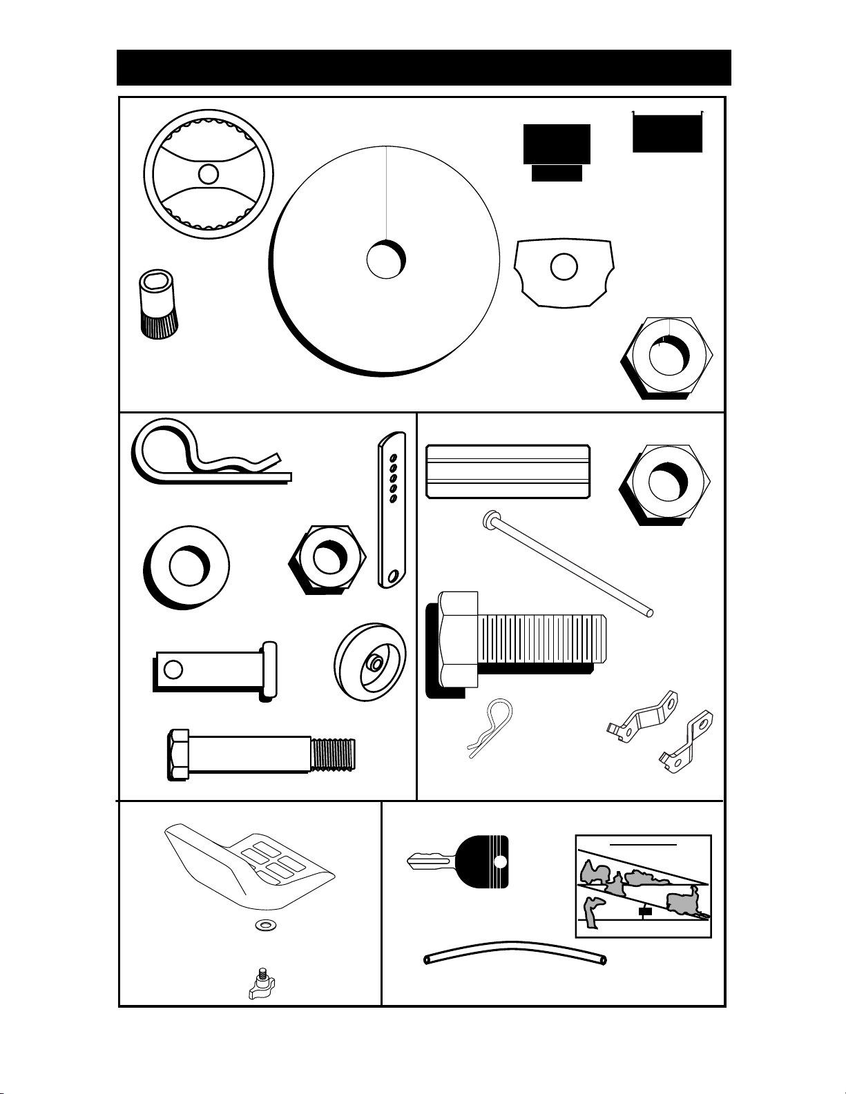
UNASSEMBLED PARTS
Steering Wheel
Steering
Sleeve
Steering
Wheel
Adapter
(1) Locknut 1/2-20
(1) Large Flat Washer
Steering
Extension
Shaft
Steering
Wheel
Insert
(4) Retainer Springs
(double loop)
(4) Washers
3/8 x 3/4 x 14 Ga.
(4) Clevis Pins
(4) Shoulder Bolt
Seat
(4) Adjusting Bar
(4) Locknut 3/8-16
(4) Wheels
Nose Roller
Rod
Retainer Spring
Keys
(2) Locknuts
5/16-18
(2) Hex Bolts
5/16-18 x 1
Nose Roller
Brackets
Slope Sheet
(1) Washer
17/32 x 1-3/16 x 12 Gauge
(1) Knob
www.mymowerparts.com
(2) Keys
(1) Oil Drain Tube
For Future Use
7
For Parts Call K&T 606-678-9623 or 606-561-4983
ASSEMBLY/PRE-OPERATION
Your new tractor has been assembled at the factory with the exception of those parts left
unassembled for shipping purposes. To ensure safe and proper operation of your tractor
all parts and hardware you as sem ble must be tightened securely. Use the correct tools
as nec es sary to in sure proper tightness. Review the video cassette before you begin.
TOOLS REQUIRED FOR ASSEMBLY
A socket wrench set will make assembly
easier. Stan dard wrench sizes you need
are listed below.
(1) 3/4" wrench (1) Pliers
(2) 7/16" wrench (1) Utility knife
(1) Tire pressure gauge
When right or left hand is mentioned in
this man ual, it means, from your point of
view, when you are in the op er at ing po sition (seat ed be hind the steer ing wheel).
TO REMOVE TRACTOR FROM
CARTON
UNPACK CARTON
1. Remove all accessible loose parts and
parts boxes from carton.
2. Cut along dotted lines on all four panels of carton. Remove end panels and
lay side panels fl at.
3. Check for any additional loose parts or
cartons and remove.
BEFORE REMOVING TRACTOR
FROM SKID
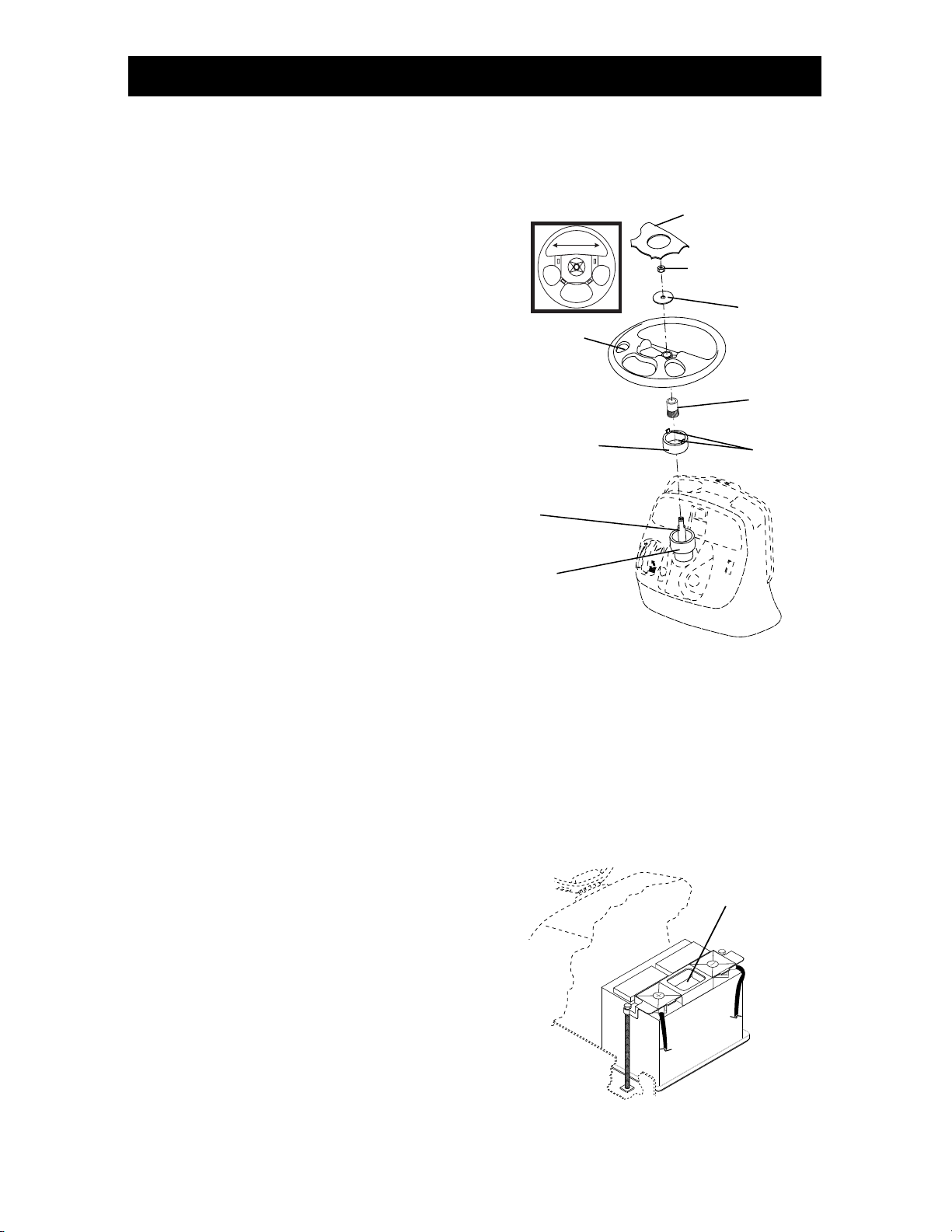
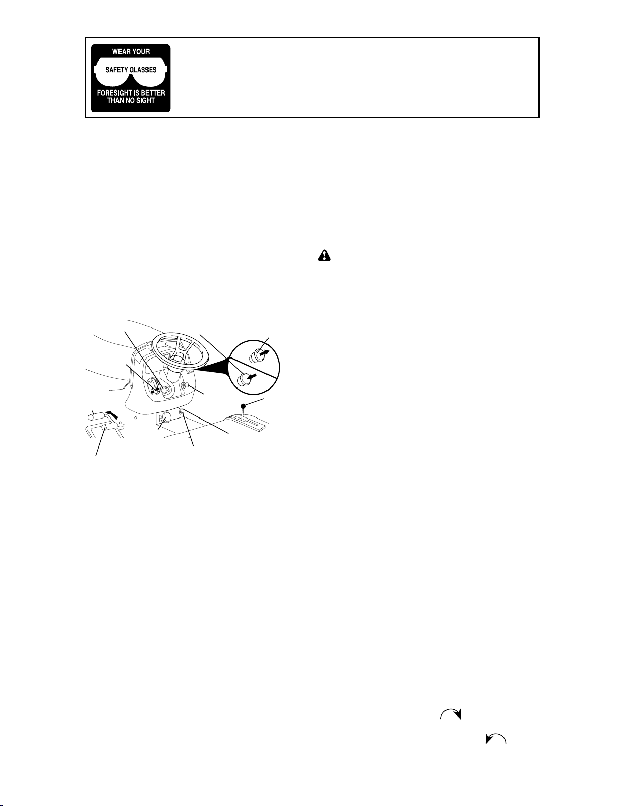
ATTACH STEERING WHEEL
1. Remove locknut and large fl at wash er
from steering shaft.
2. Position front wheels of the tractor so
they are pointing straight forward.
3. Slide the steering sleeve over the
steering shaft.
4. Align tabs and press steering sleeve
ex ten sion into bottom of steering
wheel.
5. Position steering wheel so cross bars
are horizontal (left to right) and slide
onto steering wheel adapter.
6. Secure steering wheel to steering
shaft with locknut and large fl at wash er
pre vi ous ly removed. Tighten securely.
7. Snap steering wheel insert into center
of steering wheel.
8. Remove protective materials from tractor hood and grill.
IMPORTANT: Check for and remove any
staples in skid that may puncture tires
where tractor is to roll off skid.
Steering Wheel
Insert
Lock Nut
Large Flat
Steering Wheel
Steering
Wheel Extention
Steering
Shaft
Steering
Sleeve
Washer
Steering
Wheel
Adaptor
Tabs
HOW TO SET UP YOUR TRACTOR
CHECK BATTERY
1. Lift hood to raised position.
NOTE: If this battery is put into service
after month and year indicated on label
(label located between terminals) charge
battery for minimum of one hour at 6-10
amps. (See "BATTERY" in Maintenance
section of this manual for charging instructions).
Label
8
www.mymowerparts.com
For Parts Call K&T 606-678-9623 or 606-561-4983
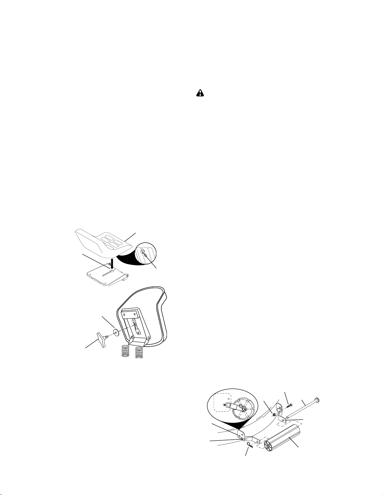
INSTALL SEAT
Adjust seat before tightening adjustment
knob.
1. Remove adjustment knob and fl at
washer securing seat to cardboard
packing and set aside for assembly of
seat to tractor.
2. Pivot seat upward and remove from
the cardboard packing. Remove the
cardboard packing and discard.
3. Place seat on seat pan so head of
shoulder bolt is positioned over large
slotted hole in pan.
4. Push down on seat to engage shoulder
bolt in slot and pull seat towards rear
of tractor.
5. Pivot seat and pan forward and as sem ble adjustment knob and fl at
washer loosely. Do not tighten.
6. Lower seat into operating position and
sit in seat.
7. Slide seat until a comfortable position
is reached which allows you to press
clutch/brake pedal all the way down.
8. Get off seat without moving its ad just ed position.
9. Raise seat and tighten adjustment
knob securely.
Seat
Seat Pan
Shoulder
02466
Flat Washer
Bolt
3. Place freewheel control in dis en gaged
po si tion to dis en gage trans mis sion
(See “TO TRANS PORT” in the Op er a tion section of this manual).
4. Roll tractor forward off skid.
TO DRIVE TRAC TOR OFF SKID (See
Op er a tion section for location and
function of con trols)
WARNING: Before start ing, read, un-
der stand and fol low all in struc tions in the
Op er a tion section of this man u al. Be sure
tractor is in a well-ventilated area. Be sure
the area in front of tractor is clear of other
peo ple and objects.
1. Be sure all the above assembly steps
have been completed.
2. Check engine oil level and fi ll fuel tank
with gasoline.
3. Place freewheel control in "trans mis sion engaged" position (see "TO
TRANSPORT" in Operation section of
this manual).
4. Sit on seat in operating position, depress brake pedal and set the parking
brake.
5. Press lift lever plunger and raise
attachment lift lever to its highest position.
6. Start the engine. After engine has
started, move throttle control to idle
position.
7. Release parking brake.
8. Slowly depress forward drive pedal and
drive tractor off skid.
9. Apply brake to stop tractor and set
park ing brake.
10.Turn ignition key to "STOP" position.
Continue with the in struc tions that follow.
Adjustment Knob
02464
NOTE: You may now roll or drive your
tractor off the skid. Follow the appropriate
instruction below to remove the tractor
from the skid.
TO ROLL TRACTOR OFF SKID (See
Op er a tion section for location and
function of con trols)
1. Press lift lever plunger and raise
attachment lift lever to its highest po si tion.
2. Release parking brake by de press ing
brake ped al.
www.mymowerparts.com
TO ATTACH NOSE ROLLER
1. Assemble brackets "A" and "B" to the
inside of mower mounting brack ets as
shown. Tighten securely.
NOTE: Be sure bracket tabs are po si tioned in tab holes in mower brackets.
2. Position nose roller between brackets
and install rod and retainer spring.
Lock
Nut
Ta b
Hole
"A"
Bracket
Retainer Spring
Hex Bolt
Rod
"B"
Bracket
Nose Roller
9
For Parts Call K&T 606-678-9623 or 606-561-4983
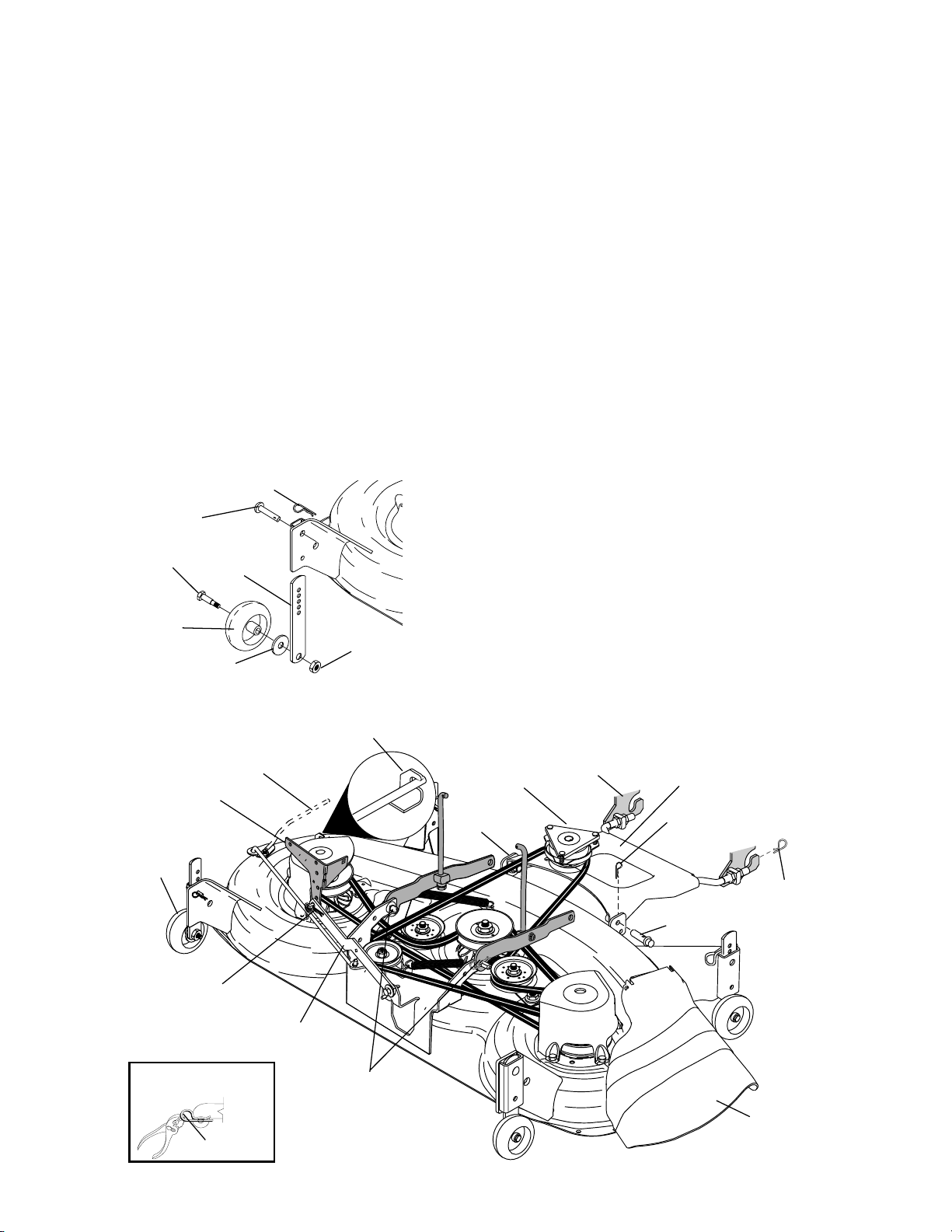
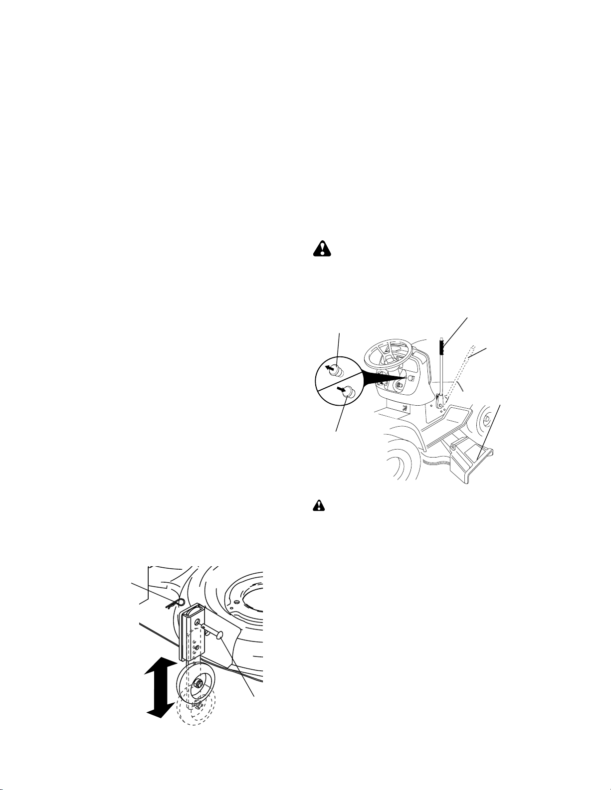
ASSEMBLE GAUGE WHEELS TO
MOWER DECK
The gauge wheels are designed to keep
the mower deck in proper position when
operating mower. Be sure they are properly adjusted to ensure optimum mower
performance.
1. Slide gauge wheel bar down into
bracket channel, Be sure that gauge
wheel bar aligning holes are on top.
As sem ble gauge wheels as shown
using shoulder bolts, 3/8 washers and
3/8-16 center locknuts and tighten
securely.
2. For ease of mower to tractor as sem bly,
raise gauge wheels to highest position
and retain with clevis pins and spring
retainers.
NOTE: Adjust gauge wheels before op er at ing mower. See “TO ADJUST GAUGE
WHEELS” in the Operation sec tion of this
manual.
Retainer Spring
Pin
Shoulder
Bolt
Gauge
Wheel
3/8 Washer
Chassis
Bracket
Gauge
Wheel
Ad just ing
Bar
3/8-16 Center
Locknut
Lock Bracket
Belt Tension Rod
Disengaged Position
INSTALL MOWER AND DRIVE
BELT
Be sure tractor is on level surface and
mower suspension arms are raised with
attachment lift control. Engage park ing
brake.
1. Cut and remove ties securing antisway bar and belts. Swing anti-sway
bar to left side of mower deck.
2. Slide mower under tractor with defl ector shield to right side of tractor.
IMPORTANT: Check belt for proper routing in all mower pulley grooves.
3. If equipped, turn height ad just ment
knob coun ter clock wise until it stops.
4. Lower mower linkage with attachment
lift control.
5. Be sure belt tension rod is in dis en gaged position.
6. Install belt into electric clutch pulley
groove.
7. Place the suspension arms on outward
pointing deck pins. Retain with double
loop re tain er spring with loops up as
shown.
8. Install front plate assembly to tractor
suspension brackets and retain with
single loop retainer springs as shown.
9. Position front plate assembly between
front mower brackets. Raise deck and
plate assembly to align holes and
insert fl anged pins. Secure pins with
double loop retainer springs between
the plate assembly and mower brack ets.
Front
Suspension
Brackets
Front Plate
Assembly
Double
Loop Retainer
Springs
Flanged
Pin
Front
Mower
Bracket
Electric
Clutch
Pulley
Single
Loop
Retainer
Springs
Double Loop
Retainer
Spring
USE PLIERS FOR
RETAINER SPRINGS
Anti-Sway
Bar
Loop Up
Suspension Arms
Double Loop
Retainer Spring
(Outward pointing
deck pins)
www.mymowerparts.com
De fl ec tor
Shield
10

For Parts Call K&T 606-678-9623 or 606-561-4983
NOTE: To assist in locating hole in fl anged
pin, the hole in pin is inline with notch on
head of pin. If necessary, move mower
side-to-side to give space between plate
and mower brackets.
IMPORTANT: Check belt for proper routing in all mower pulley grooves.
10.Engage belt tension rod by pushing
rod into locking bracket.
CAUTION: Belt tension rod is spring
loaded. Have a tight grip on rod and engage slowly.
11.Connect anti-sway bar to chassis
bracket under left foot rest and retain
with double loop retainer spring.
12.If equipped, turn height adjustment
knob clock wise to remove slack from
mower sus pen sion.
13.Raise deck to highest position.
14.Adjust gauge wheels before op er at ing
mower as shown in the Operation section of this manual.
CHECK TIRE PRESSURE
The tires on your tractor were overinfl ated
at the factory for shipping purposes. Correct tire pressure is important for best
cutting performance.
• Reduce tire pressure to PSI shown in
“PRODUCT SPEC I FI CA TIONS” section
of this manual.
CHECK DECK LEVELNESS
For best cutting results, mower housing
should be properly leveled. See “TO LEVEL MOWER HOUSING” in the Service
and Adjustments section of this manual.
CHECK FOR PROPER POSITION
OF ALL BELTS
See the fi gures that are shown for replacing motion and mower blade drive belts
in the Service and Adjustments sec tion
of this manual. Verify that the belts are
routed cor rect ly.
CHECK BRAKE SYSTEM
After you learn how to operate your tractor, check to see that the brake is properly
adjusted. See “TO ADJUST BRAKE” in
the Service and Adjustments section of
this manual.
✔
CHECKLIST
Before you operate your new trac tor, we
wish to as sure that you re ceive the best
performance and sat is fac tion from this
quality product.
Please review the following checklist:
✓ All assembly instructions have been
com plet ed.
✓ No remaining loose parts in carton.
✓ Battery is properly prepared and
charged. (Minimum 1 hour at 6 amps).
✓ Seat is adjusted comfortably and tight-
ened securely.
✓ All tires are properly infl ated. (For ship-
ping purposes, the tires were over in fl ated at the factory).
✓ Be sure mower deck is properly lev eled
side-to-side/front-to-rear for best cutting
results. (Tires must be properly in fl at ed
for leveling).
✓ Check mower and drive belts. Be sure
they are routed prop er ly around pul leys
and inside all belt keepers.
✓ Check wiring. See that all connections
are still secure and wires are properly
clamped.
✓ Before driving tractor, be sure free wheel
control is in “transmission engaged”
position (see “TO TRANS PORT” in the
Operation section of this man u al).
While learning how to use your tractor, pay
extra attention to the following im por tant
items:
✓ Engine oil is at proper level.
✓ Fuel tank is fi lled with fresh, clean, reg-
u lar unleaded gas o line.
✓ Become familiar with all controls - their
location and func tion. Operate them
be fore you start the engine.
✓ Be sure brake system is in safe op er -
at ing condition.
✓ It is important to purge the trans mis sion
before op er at ing your tractor for the fi rst
time. Follow proper starting and trans-
mis sion purg ing instructions (See “TO
START EN GINE” and “PURGE TRANS-
MIS SION” in the Op er a tion sec tion of
this man u al).
11
www.mymowerparts.com
For Parts Call K&T 606-678-9623 or 606-561-4983
OPERATION
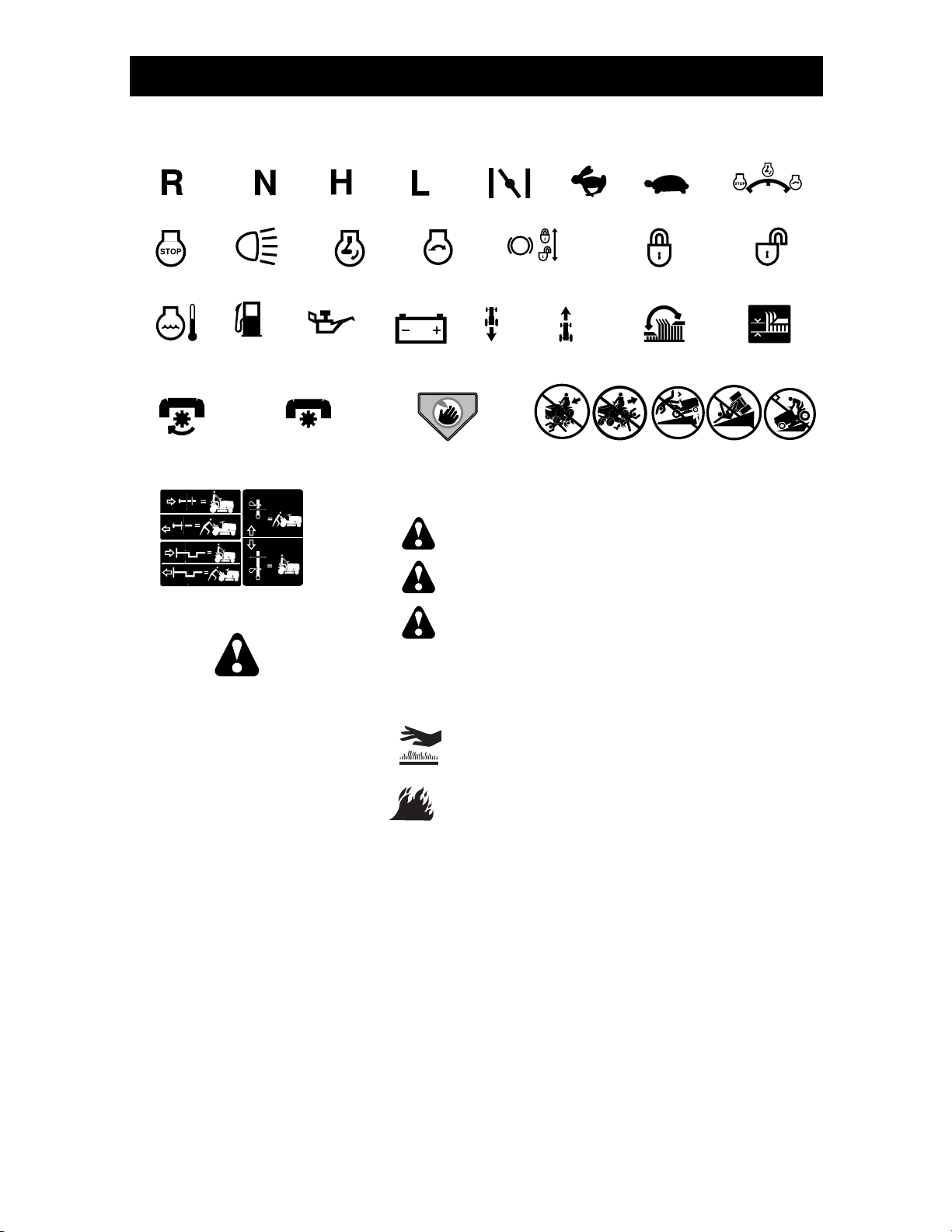
These symbols may appear on your tractor or in literature supplied with the product.
Learn and understand their meaning.
REVERSE
ENGINE OFF
OVER TEMP
LIGHT
ATTACHMENT
CLUTCH ENGAGED
FREE WHEEL
(Automatic Models only)
NEUTRAL
LIGHTS ON
FUEL
OIL PRESSURE
ATTACHMENT
CLUTCH DISENGAGED
HIGH
ENGINE ON
LOW
ENGINE START
BATTERY
DANGER, KEEP HANDS
AND FEET AWAY
CHOKE
PARKING BRAKE
REVERSE
DANGER indicates a hazard which, if not avoided,
will result in death or serious injury.
WARNING indicates a hazard which, if not avoided,
could result in death or serious injury.
CAUTION indicates a hazard which, if not avoided,
might result in minor or moderate injury.
FAST
P
FORWARD
KEEP AREA CLEAR
SLOW
PARKING BRAKE
LOCKED
MOWER HEIGHT
15
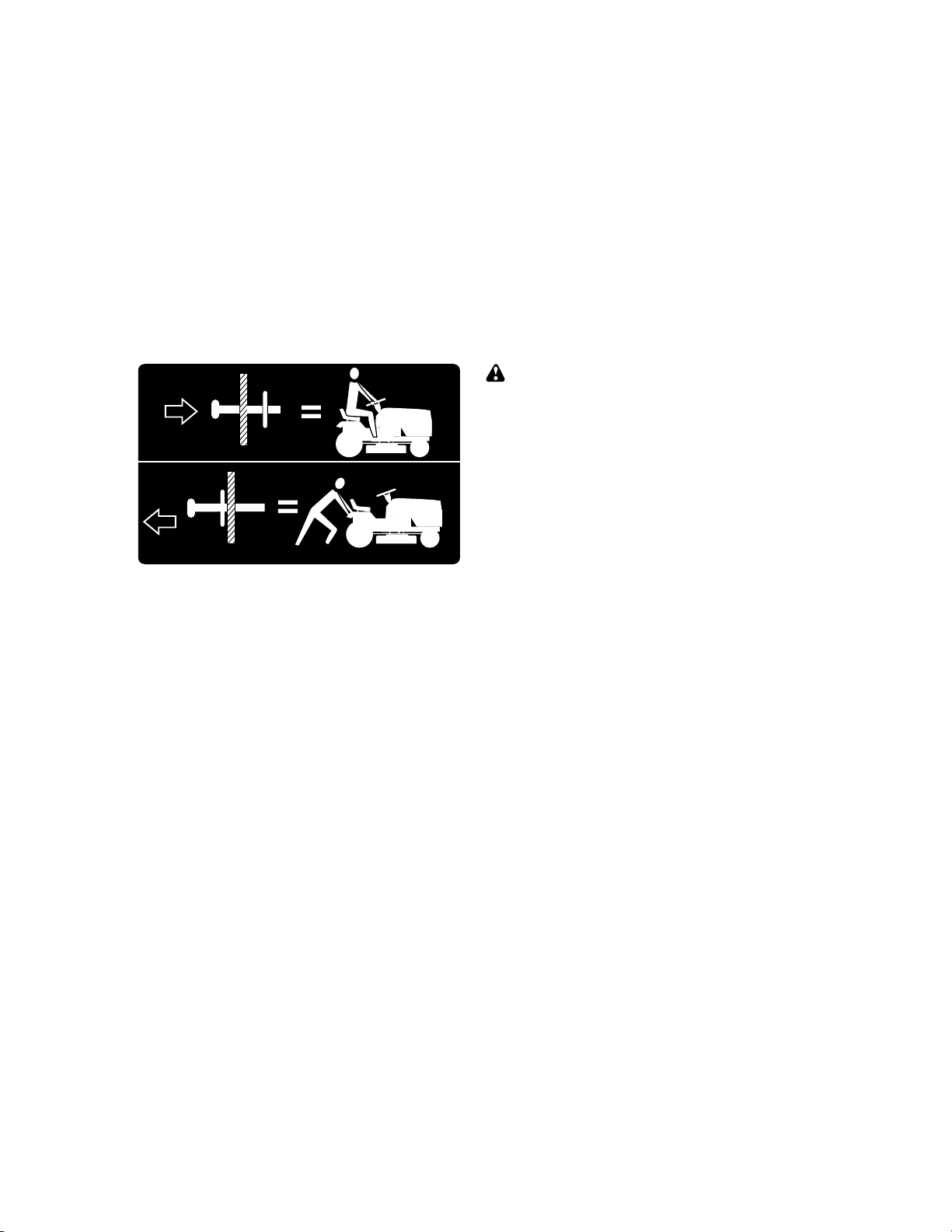
SLOPE HAZARDS
(SEE SAFETY RULES SECTION)
IGNITION
PARKING BRAKE
UNLOCKED
MOWER LIFT
15
Failure to follow instructions
could result in serious injury or
death. The safety alert symbol
is used to identify safety information about hazards which can
result in death, serious injury
and/or property damage.
CAUTION when used without the alert symbol,
indicates a situation that could result in damage
to the tractor and/or engine.
HOT SURFACES indicates a hazard which,
if not avoided, could result in death, serious injury
and/or property damage.
FIRE indicates a hazard which, if not avoided,
could result in death, serious injury and/or
property damage.
12
www.mymowerparts.com
For Parts Call K&T 606-678-9623 or 606-561-4983
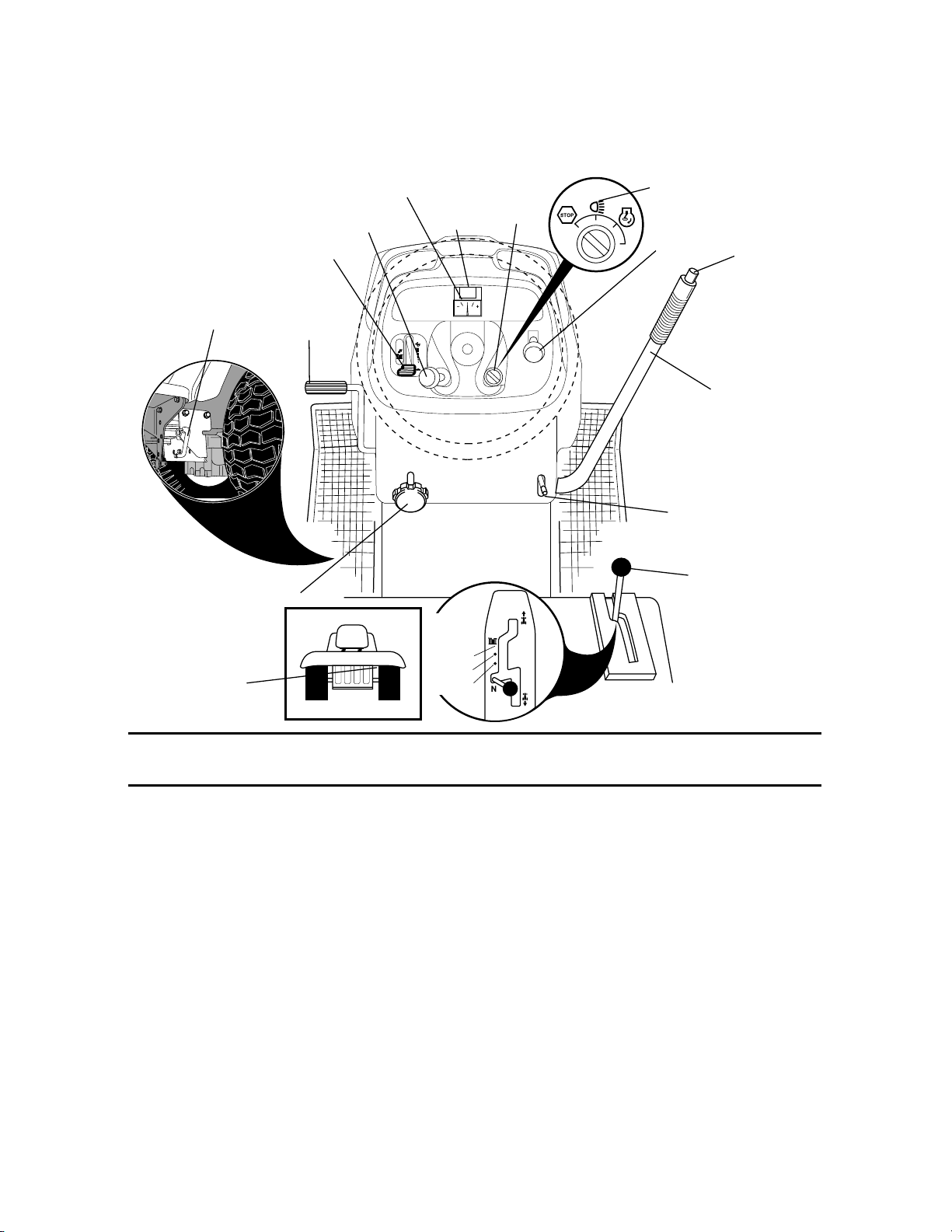
KNOW YOUR TRACTOR
READ THIS OWNER'S MANUAL AND SAFETY RULES BEFORE OPERATING YOUR
TRACTOR
Compare the illustrations with your tractor to familiarize yourself with the locations of
various controls and ad just ments. Save this manual for future reference.
Light Switch
Position
Attachment
Clutch
Switch
Attachment
Lift Lever
Lift
Lever
Plunger
Motion Drive
Belt Tension
Handle
Throttle
Control
Brake Pedal
Choke
Control
Ammeter
Hourmeter
Ignition
Switch
Height
Adjustment
Knob
Free Wheel
Control
Approx.
Speed:
3MPH
2MPH
1MPH
Our tractors conform to the safety standards of the
American National Stan dards Institute.
ATTACHMENT CLUTCH SWITCH - Used
to engage the mower blades, or other attachments mounted to your trac tor.
LIGHT SWITCH POSITION - Turns the
head lights on and off.
THROTTLE CONTROL - Used to con trol
engine speed.
BRAKE PEDAL - Used for braking the
tractor and starting the engine.
CHOKE CONTROL - Used when start ing
a cold engine.
HEIGHT ADJUSTMENT KNOB - Used to
adjust the mow er cutting height.
IGNITION SWITCH - Used for starting and
stopping the engine.
ATTACHMENT LIFT LEVER - Used to raise
and lower the mower deck or other at tach ments
mounted to your tractor.
Parking Brake
Lever
Motion Control
Lever
LIFT LEVER PLUNGER - Used to re lease
attachment lift lever when chang ing its
position.
AMMETER - Indicates charging (+) or
discharging (-) of battery.
PARKING BRAKE LEVER - Locks brake
pedal into the brake po si tion.
MOTION CONTROL LEVER - Selects the
speed and direction of tractor.
FREEWHEEL CONTROL - Disengages
transmission for pushing or slowly towing
the tractor with the engine off.
MOTION DRIVE BELT TENSION HAN DLE - Used when changing motion drive
belt and, if necessary, starting engine
under extremely cold conditions.
HOURMETER - Indicates hours of operation.
13
www.mymowerparts.com
For Parts Call K&T 606-678-9623 or 606-561-4983
The operation of any tractor can result in foreign objects thrown into
the eyes, which can result in severe eye dam age. Always wear safety
glass es or eye shields while operating your tractor or per form ing any
ad just ments or repairs. We rec om mend standard safety glasses or a
wide vision safety mask worn over spectacles.
HOW TO USE YOUR TRAC TOR
TO SET PARKING BRAKE
Your tractor is equipped with an operator
presence sens ing switch. When engine
is running, any attempt by the op er a tor
to leave the seat without fi rst setting the
parking brake will shut off the engine.
1. Depress brake pedal all the way down
and hold.
2. Pull parking brake lever up and re lease
pres sure from brake pedal. Pedal
should re main in brake po si tion. Make
sure parking brake will hold tractor
secure.
Choke
Control
Throttle
Control
Brake
Pedal
Height
Adjustment
Knob
Brake Pedal
“Drive” Position
Push-In to
“Disengage”
“Disengaged”
Position
STOPPING
MOWER BLADES -
• To stop mower blades, push at tach ment
clutch switch in to disengaged position.
GROUND DRIVE -
• To stop ground drive, depress brake
pedal all the way down.
IMPORTANT: The motion control lever
returns to neutral (N) position when the
brake pedal is fully depressed.
ENGINE -
• Move throttle control to slow po si tion.
NOTE: Failure to move throttle control to
slow position to allow engine to idle before
stopping may cause engine to “back fi re”.
• Turn ignition key to “STOP” position and
remove key. Always remove key when
leaving tractor to prevent un au tho rized
use.
• Never use choke to stop engine.
Attachment Clutch
Switch Pull Out to
“Engage”
Ignition
Key
Motion
Control
Lever
Parking Brake
“Engaged”
Position
IMPORTANT: Leaving the ignition switch
in any position other than "STOP" will
cause the battery to discharge and go
dead.
NOTE: Under certain conditions when
tractor is standing idle with the engine
running, hot engine exhaust gases may
cause “browning” of grass. To elim i nate
this possibility, always stop en gine when
stopping tractor on grass areas.
CAUTION: Always stop tractor com plete ly, as de scribed above, before leav ing
the operator's position.
TO USE THROTTLE CON TROL
Always operate engine at full throttle.
• Operating engine at less than full
throttle reduces the battery charg ing
rate.
• Full throttle of fers the best mower per-
for mance.
TO USE CHOKE CONTROL
Use choke control whenever you are starting a cold engine. Do not use to start a
warm engine.
• To engage choke control, pull knob out.
Slowly push knob in to dis en gage.
TO MOVE FORWARD AND
BACKWARD
CAUTION: Do not attempt to operate mo-
tion control lever when the parking brake
is set or when the brake pedal is depressed. Doing so may result in misadjustment to the drive con trol system.
The direction and speed of movement is
controlled by the motion control lever.
1. Start tractor with motion control le ver in
neutral (N) position.
2. Release parking brake.
3. Slowly move motion control lever to
desired position.
TO ADJUST MOWER CUT TING HEIGHT
The cutting height is controlled by turn ing the height ad just ment knob in desired
direction.
• Turn knob clockwise (
) to raise cut-
ting height.
• Turn knob counterclockwise (
lower cutting height.
14
) to
www.mymowerparts.com
For Parts Call K&T 606-678-9623 or 606-561-4983
The cutting height range is ap prox i mate ly
1-1/2" to 4-1/2". The heights are mea sured from the ground to the blade tip with
the engine not running.
These heights are ap proxi mate and may
vary depending upon soil conditions,
height of grass and types of grass being
mowed.
• The average lawn should be cut to
approximately 2-1/2 inches during the
cool season and to over 3 inches during
hot months. For healthier and better
looking lawns, mow often and after moderate growth.
• For best cutting performance, grass over
6 inches in height should be mowed
twice. Make the fi rst cut relatively high;
the second to de sired height.
TO ADJUST GAUGE WHEELS
Gauge wheels are properly adjusted
when they are slightly off the ground when
mower is at the desired cutting height in
operating position. Gauge wheels then
keep the deck in proper position to help
prevent scalping in most terrain conditions.
NOTE: Be sure tractor is on a fl at level
surface.
1. Lower mower and adjust mower to
desired cutting height.
2. Remove retainer spring and clevis pin
which secure each gauge wheel bar.
3. Lower gauge wheels to ground. Raise
gauge wheels slightly to align holes
in bracket and gauge wheel bar and
insert clevis pin. Gauge wheels should
be slightly off the ground.
4. Replace retainer spring into clevis pin.
5. Be sure all gauge wheels are in the
same setting.
IMPORTANT: Be sure to readjust gauge
wheels if you change the cutting height
of the mower deck.
Retainer
Spring
Clevis
Pin
TO OPERATE MOWER
Your tractor is equipped with an operator
presence sensing switch. Any attempt
by the operator to leave the seat with the
engine running and the attachment clutch
engaged will shut off the engine. You must
remain fully and centrally positioned in the
seat to prevent the engine from hesitating
or cutting off when operating your equipment on rough, rolling terrain or hills.
1. Select desired height of cut.
2. Lower mower with attachment lift control.
3. Start mower blades by engaging attachment clutch control.
TO STOP MOWER BLADES disengage attachment clutch con trol.
CAUTION: Do not operate the mower
without either the en tire grass catcher,
on mowers so equipped, or the defl ector
shield in place.
Attachment Clutch
Switch Pull Out to
“Engage”
Attachemnt Lift
Lever High Position
Low
Position
Defl ector
Shield
Push-In to
“Disengage”
TO OPERATE ON HILLS
WARNING: Do not drive up or down
hills with slopes greater than 15° and do
not drive across any slope. Use the slope
guide provided at the back of this manual.
• Choose the slowest speed before start-
ing up or down hills.
• Avoid stopping or changing speed on
hills.
• If stopping is absolutely necessary, push
brake pedal quickly to brake position
and engage parking brake.
IMPORTANT: The motion control lever
returns to neutral (N) position when the
brake pedal is de pressed.
• To restart movement, slowly re lease
parking brake and brake ped al.
• Slowly move motion control lever to
slowest setting.
• Make all turns slowly.
15
www.mymowerparts.com
For Parts Call K&T 606-678-9623 or 606-561-4983
TO TRANSPORT
When pushing or towing your tractor, be
sure to disengage transmission by placing
freewheel control in free wheel ing po si tion.
Freewheel control is located at the rear
drawbar of tractor.
1. Raise attachment lift to highest position with at tach ment lift control.
2. Pull freewheel control out and into the
slot and release so it is held in the
disengaged position.
• Do not push or tow tractor at more than
two (2) MPH.
• To re-engage transmission, reverse
above procedure.
Transmission Engaged
Transmission Disengaged
NOTE: To protect hood from damage
when transporting your tractor on a truck
or a trailer, be sure hood is closed and
secured to tractor. Use an appropriate
means of tying hood to tractor (rope, cord,
etc.).
TOWING CARTS AND OTHER AT TACH MENTS
Tow only the attachments that are rec om mend ed by and comply with spec i fi ca tions
of the manufacturer of your tractor. Use
common sense when tow ing. Too heavy
of a load, while on a slope, is dangerous.
Tires can lose traction with the ground and
cause you to lose control of your tractor.
BEFORE STARTING THE ENGINE
CHECK ENGINE OIL LEVEL
The engine in your tractor has been
shipped, from the factory, already fi lled
with sum mer weight oil.
1. Check engine oil with tractor on level
ground.
2. Remove oil fi ll cap/dipstick and wipe
clean, reinsert the dipstick and screw
cap tight, wait for a few seconds, remove and read oil level. If nec es sary,
add oil until “FULL” mark on dipstick is
reached. Do not overfi ll.
• For cold weather operation you should
change oil for easier starting (See the
oil viscosity chart in the Main te nance
sec tion of this man u al).
• To change engine oil, see the Main te nance section in this manual.
ADD GASOLINE
• Fill fuel tank to bottom of fi ller neck. Do
not overfi ll. Use fresh, clean, regular
un lead ed gasoline with a minimum of
87 octane. (Use of leaded gasoline will
increase carbon and lead oxide deposits
and reduce valve life). Do not mix oil
with gasoline. Purchase fuel in quan ti ties that can be used within 30 days to
assure fuel freshness.
CAUTION: Wipe off any spilled oil or
fuel. Do not store, spill or use gasoline
near an open fl ame.
IMPORTANT: When operating in temperatures below32°F(0°C), use fresh, clean
winter grade gas o line to help insure good
cold weather start ing.
CAUTION: Alcohol blended fuels (called
gasohol or using ethanol or methanol) can
attract moisture which leads to separation and for ma tion of acids during storage.
Acidic gas can damage the fuel system
of an engine while in storage. To avoid
engine problems, the fuel system should
be emptied before stor age of 30 days
or longer. Drain the gas tank, start the
engine and let it run until the fuel lines
and carburetor are empty. Use fresh fuel
next season. See Storage In struc tions for
additional information. Never use engine
or carburetor cleaner products in the fuel
tank or permanent damage may occur.
TO START ENGINE
When starting the engine for the fi rst time
or if the engine has run out of fuel, it will
take extra cranking time to move fuel from
the tank to the engine.
1. Be sure freewheel control is in the
trans mis sion en gaged position.
2. Sit on seat in operating position,
depress brake pedal and set parking
brake.
3. Move attachment clutch to dis en gaged
po si tion.
4. Move throttle control to fast position
5. Pull choke control out for a cold engine
start attempt. For a warm engine start
attempt the choke con trol may not be
needed.
NOTE: Before starting, read the warm and
cold starting procedures below.
16
www.mymowerparts.com
 Loading...