

Page 1
Title: Southern States –
LLS-I-2000, LLS-II-2000 and LLS-II-3000
Load and Line Switchers
TABLE OF CONTENTS
1.0 SCOPE.......................................................................................................................2
2.0 STANDARDS .............................................................................................................2
3.0 DESIGN REQUIREMENTS........................................................................................2
3.01 Service Conditions................................................................................................. 2
3.02 Ratings................................................................................................................... 2
3.03 Interrupter .............................................................................................................. 3
3.04 SF6 Gas System .................................................................................................... 3
3.05 Operating Mechanism............................................................................................ 3
4.0 DESIGN TESTS.........................................................................................................3
5.0 PRODUCTION TESTS...............................................................................................3
5.01 Mechanical Operations Test .................................................................................. 3
5.02 Leak Test............................................................................................................... 4
5.03 Resistance Test..................................................................................................... 4
5.04 Dielectric Test........................................................................................................ 4
6.0 SPARE PARTS ..........................................................................................................4
7.0 DOCUMENTATION REQUIREMENTS......................................................................4
7.01 Approval Drawings................................................................................................. 4
7.02 Final Drawings....................................................................................................... 4
7.03 Instruction Books ................................................................................................... 4
7.04 Additional Documentation...................................................................................... 5
8.0 SHIPPING and DELIVERY.........................................................................................5
9.0 WARRANTY...............................................................................................................5
10.0 ACCEPTABLE LOAD and LINE SWITCHER.............................................................5
Product Specification Guide
PAGE
Page 1 of 5 Publication No.: PSG-805-080109
Page 2
Title: Southern States –
LLS-I-2000, LLS-II-2000 and LLS-II-3000
Product Specification Guide
Load and Line Switchers
1.0 SCOPE
This specification covers the design, manufacture, and testing of outdoor load and line
switchers.
2.0 STANDARDS
All outdoor load and line switchers shall be designed, manufactured, assembled, and
tested in accordance with the latest applicable ANSI, NEMA, IEEE, and ASTM
standards and guidelines. If there are any conflicts between the ANSI, NEMA, IEEE, or
ASTM standards and this specification the specification shall govern.
3.0 DESIGN REQUIREMENTS
3.01 Service Conditions
The load and line switcher shall be suitable for outdoor installation in electric
power substations and on transmission line applications under the following
conditions:
3.01.01 Temperature
The load and line switcher shall perform in an ambient temperature
range of -40oC through +50oC.
3.01.02 Altitude
The load and line switcher shall perform at elevations up to 3,300 feet.
3.01.03 Additional Requirements
If any site specific service conditions not covered in sections 3.01.01 and
3.01.02 exist (e.g. extreme cold temperature installation, high altitude
installation, etc.) they will be defined in the quotation request.
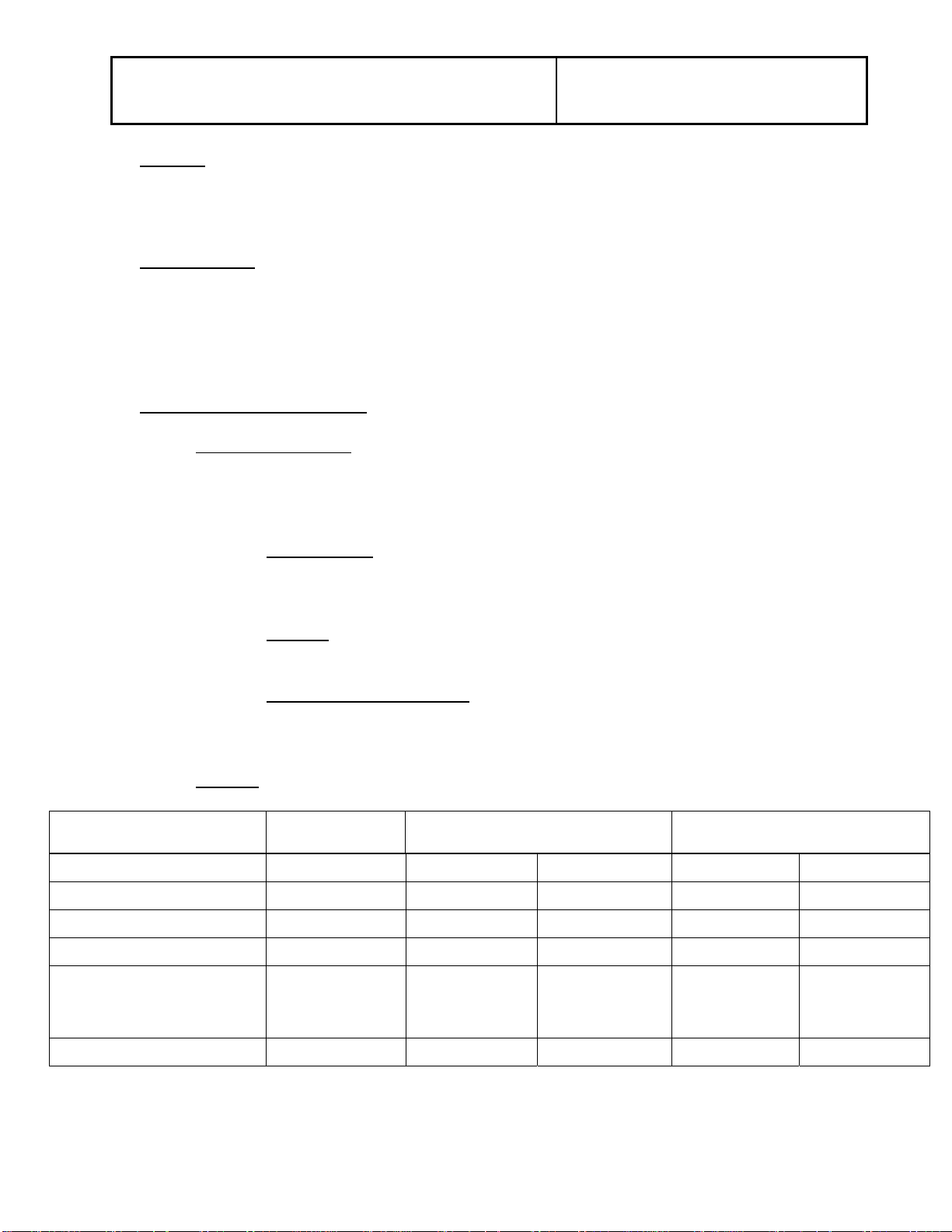
3.02 Ratings
Design Characteristics LLS-I-2000 LLS-II-2000 LLS-II-3000
Maximum Voltage 38 kV – 72.5 kV 72.5 kV -170 kV 245 kV 72.5 kV -170 kV 245 kV
Load Breaking Capability 2000 A 2000 A 2000 A 3000 A 2000 A
Line Dropping Capability 300 A 300 A 200 A 300 A 200 A
Loop Splitting Capability 2000 A 2000 A 2000 A 3000 A 3000 A
55 psig at 20ºC
Nominal Operating Pressure 65 psig at 20ºC
Full Load Operations 2000 2000 2000 2000 2000
for 72.5 kV, 65
psig at 20ºC for
123 kV-170 kV
65 psig at 20ºC
55 psig at 20ºC
for 72.5 kV, 65
psig at 20ºC for
123 kV-170 kV
65 psig at 20ºC
Page 2 of 5 Publication No.: PSG-805-080109
Page 3

Title: Southern States –
LLS-I-2000, LLS-II-2000 and LLS-II-3000
Load and Line Switchers
3.03 Interrupter
The load and line switcher shall use SF6 single gap puffer interrupters. Vacuum
interrupters or multigap SF6 interrupters are unacceptable. Each interrupter shall
be housed in an ANSI 70 gray composite or epoxy insulator that will not degrade
when exposed to the sun’s UV rays. Fiberglass housed interrupters without
silicone outer coatings and porcelain housed interrupters are unacceptable.
3.04 SF6 Gas System
The gas system shall include the insulator and a color-coded, temperature
compensated density gauge that is visible from the ground.
A means for refilling the system in the field without disassembling the interrupter
must be provided. The device shall have a leak rate of less than 0.5% per year.
3.05 Operating Mechanism
Each interrupter shall be provided with a spring open mechanism and shall reset
itself when the switch is in the open position.
Product Specification Guide
4.0 DESIGN TESTS
The load and line switcher shall be design tested in accordance with IEEE Std. 1247-
1998, Standard for Interrupter Switches for Alternating Current Rated Above 1,000
Volts. The testing shall include dielectric tests, power tests, an environmental test, and
a mechanical endurance test. The dielectric tests shall include 60 Hz power frequency,
lighting impulse withstand, and visual corona. The power tests shall demonstrate the
capability to perform load breaking, line dropping, and loop splitting. The power tests
and the dielectric tests shall be performed at full voltage on the complete interrupter
assembly. Testing individual modules is not acceptable. The environmental test shall
demonstrate the load and line switcher’s capability to perform over a temperature range
of –40ºC to +50ºC. The load and line switcher shall be endurance tested to 2000
operations.
5.0 PRODUCTION TESTS
Each load and line switcher shall be fully assembled at the factory, adjusted, tested, and
timed per IEEE Std. 1247-1998. The tests shall include:
5.01 Mechanical Operations Test
There shall be at least 25 mechanical operations performed at the factory.
Timing tests shall be recorded.
Page 3 of 5 Publication No.: PSG-805-080109
Page 4

Title: Southern States –
LLS-I-2000, LLS-II-2000 and LLS-II-3000
Load and Line Switchers
5.02 Leak Test
An SF6 leak test shall be performed to confirm the leak rate is less than 0.5% per
year.
5.03 Resistance Test
5.03.01 Current Path Resistance Test
A micro-ohm resistance check shall be performed on each interrupter
using a 100 A DC source and the values shall be recorded.
5.04 Dielectric Test
5.04.01 Interrupter Dielectric Test
Each complete interrupter assembly shall pass a 60 Hz power frequency
withstand test for one minute.
6.0 SPARE PARTS
Product Specification Guide
No spare parts shall be required at the time of load and line switcher purchase. Stock
shall be maintained at the manufacturer and available for rush shipment in the event of
an emergency need.
7.0 DOCUMENTATION REQUIREMENTS
7.01 Approval Drawings
The manufacturer shall furnish approval drawings in AutoCAD .DWG format via
e-mail. The purchase order will designate the name and e-mail address of the
individual where the drawings should be forwarded. If there are no comments to
the approval drawings purchaser will respond via e-mail that drawings are
approved as submitted with no changes. If comments are required then one
copy of the drawings will be returned to the manufacturer within 10 days from the
date of transmittal marked “approved with comments as noted”.
7.02 Final Drawings
The manufacturer shall furnish final drawings in AutoCAD .DWG format via email. Unless otherwise specified in the purchase order, the final drawings will be
forwarded to the same individual that the approval drawings were sent to.
7.03 Instruction Books
The manufacturer shall furnish an electronic copy of each applicable instruction
book in Adobe Acrobat .PDF format via e-mail. Unless otherwise specified in the
purchase order, the instruction book(s) will be forwarded to the same individual
that the approval drawings were sent to.
Page 4 of 5 Publication No.: PSG-805-080109
Page 5

Title: Southern States –
LLS-I-2000, LLS-II-2000 and LLS-II-3000
Load and Line Switchers
7.04 Additional Documentation
One complete set of final drawings and one copy of each applicable instruction
book shall be shipped in a weatherproof envelope with each load and line
switcher.
8.0 SHIPPING and DELIVERY
Each interrupter shall be shipped fully pressurized with SF6, eliminating the need to pull
a vacuum on the interrupters in the field.
9.0 WARRANTY
All load and line switchers and their accessories furnished under this specification shall
be covered by a five-year warranty from date of shipment against failure due to design
or to defects in workmanship or material.
10.0 ACCEPTABLE LOAD and LINE SWITCHER
Product Specification Guide
Load and Line switchers, Type LLS-I or LLS-II, as manufactured by Southern States
are approved. Alternative products must meet or exceed this specification and be
approved for use by the USER prior to the bid date.
Page 5 of 5 Publication No.: PSG-805-080109
 Loading...