

Page 1

Title: Southern States – CSV
Vertical Interrupter Style Circuit Switcher
Product Specification Guide
TABLE OF CONTENTS
PAGE
1.0 SCOPE ..................................................................................................................... 2
2.0 STANDARDS ............................................................................................................ 2
3.0 DESIGN REQUIREMENTS ................................ ....................................................... 2
3.01 Service Conditions ................................................................................................ . 2
3.02 Ratings .................................................................................................................. 3
3.03 Interrupter .............................................................................................................. 4
3.04 Insulators ............................................................................................................... 4
3.05 SF6 Gas System .................................................................................................... 5
3.06 Terminal Pads ....................................................................................................... 5
3.07 Operating Mechanism ............................................................................................ 5
3.08 Ground Pads ......................................................................................................... 6
4.0 MANUFACTURING REQUIREMENTS ..................................................................... 6
4.01 Wiring .................................................................................................................... 6
4.02 Base Frame ........................................................................................................... 6
4.03 Support Structure ................................................................................................... 6
5.0 DESIGN TESTS ........................................................................................................ 7
6.0 PRODUCTION TESTS .............................................................................................. 7
6.01 Mechanical Operation ............................................................................................ 7
6.02 Leak Test ............................................................................................................... 7
6.03 Resistance Tests ................................................................................................ ... 7
6.04 Dielectric Tests ...................................................................................................... 7
7.0 SPARE PARTS ......................................................................................................... 8
8.0 DOCUMENTATION REQUIREMENTS ................................ ..................................... 8
8.01 Approval Drawings ................................................................................................. 8
8.02 Final Drawings ....................................................................................................... 8
8.03 Instruction Books ................................................................................................ ... 8
8.04 Additional Documentation ...................................................................................... 8
9.0 SHIPPING and DELIVERY ........................................................................................ 8
10.0 WARRANTY .............................................................................................................. 9
11.0 SPECIFIC QUOTE REQUIREMENTS....................................................................... 9
12.0 ACCEPTABLE CIRCUIT SWITCHER ....................................................................... 9
Page 1 of 9 Publication No.: PSG-806-06012011
Page 2
Title: Southern States – CSV
Vertical Interrupter Style Circuit Switcher
Product Specification Guide
1.0 SCOPE
This specification covers the design, manufacture, and testing of three pole, gang
operated vertical interrupter outdoor circuit switchers without integral disconnect.
2.0 STANDARDS
All outdoor circuit switchers shall be designed, manufactured, assembled, and tested in
accordance with the latest applicable ANSI, NEMA, and ASTM standards and
guidelines. If there are any conflicts between the ANSI, NEMA, or ASTM standards and
this specification the specification shall govern.
3.0 DESIGN REQUIREMENTS
3.01 Service Conditions
The circuit switcher shall be suitable for outdoor installation in electric power
substations under the following conditions:
3.01.01 Temperature
The circuit switcher shall perform in an ambient temperature range of
-40oC through +50oC.
3.01.02 Altitude
The circuit switcher shall perform at elevations up to 3,300 feet.
3.01.03 Seismic
The circuit switcher shall be capable of withstanding seismic loading of
0.2 g ground acceleration in any direction when installed on the
manufacturer’s furnished support structure and anchor bolts and with
flexible connections to the terminal pads. The circuit switcher shall
perform its specified functions during and after the seismic event.
3.01.04 Wind Loading
The circuit switcher shall be capable of withstanding wind loads up to
90 mph without loss of function.
3.01.05 Additional Requirements
If any site specific service conditions not covered in sections 3.01.01
through 3.01.04 exists (e.g. extreme cold temperature installation,
corrosive environment, high altitude installation, etc.) they will be defined
in the quotation request.
Page 2 of 9 Publication No.: PSG-806-CSV 06012011
Page 3
Title: Southern States – CSV
Vertical Interrupter Style Circuit Switcher
Product Specification Guide
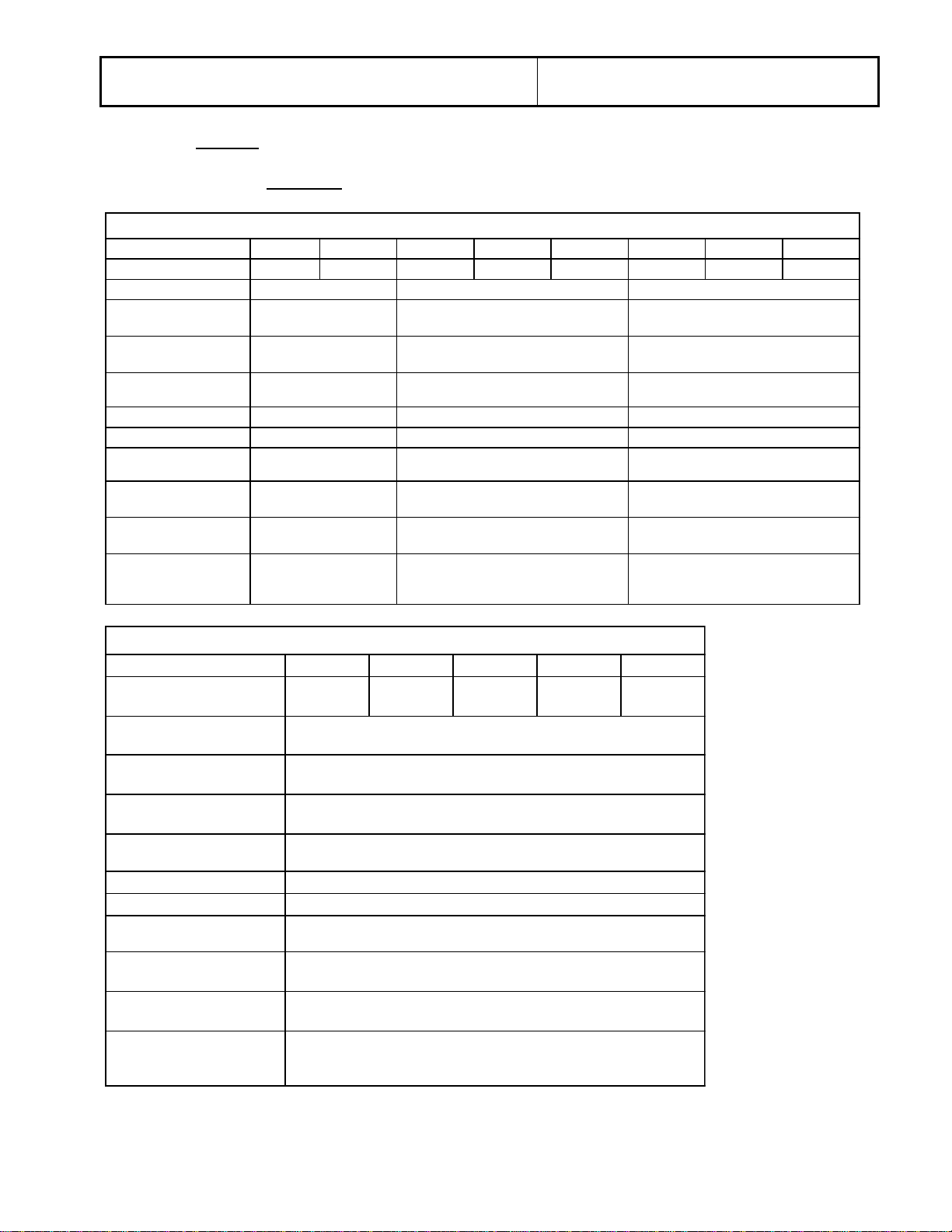
Maximum kV Rating 27 38 38 48.3 72.5 38 48.3 72.5
BIL (kV) 150 200 200 250 350 200 250 350
Continuous Current
Primary Fault
Interrupting
Secondary Thru-Fault
Interrupting
Interrupting Time
Power Frequency
Short-Time Withstand
Peak Withstand
Short-Circuit Making
Insulator Design
Ambient Temperature
Range
-40º C to +50º C
1200 A
25 kA
5 cycles
-40º C to +50º C standard
(-50º C to +50º C optional)
Porcelain
Composite
Porcelain
3 cycles
40 kA
1200 A, 1600 A, 2000 A, 2500 A
4
Ratings
62.5 kA
25 kA
50/60 Hz
1200 A & 1600 A
25 kA
5 cycles
50/60 Hz
25 kA (3 sec)
4
-30º C to +50º C
40 kA
104 kA
40 kA (3 sec)
4
60 Hz
40 kA (3 sec)
104 kA
40 kA (3 sec)
Maximum kV Rating 48.3 72.5 123 145 170
Interrupter/Blade BIL (kV) 250 350 550 650 750
Continuous Current
Primary Fault Interrupting
Secondary Thru-Fault
Interrupting
Interrupting Time
Power Frequency
Short-Time Withstand
Peak Withstand
Short-Circuit Making
Insulator Design
Ambient Temperature
Range
*
4000 A rating is only available thru 145 kV.
40 kA (3 sec), 63 kA (1 sec)
164 kA
63 kA
Porcelain
-40º C to +50º C standard
(-50o C to +50o C optional)
Ratings
1200 A,1600 A, 2000 A, 3000 A, 4000 A*
25 kA, 31.5 kA, 40 kA
4
3 cycles
60 Hz
3.02 Ratings
3.02.01 Electrical
Page 3 of 9 Publication No.: PSG-806-CSV 06012011
Page 4

Title: Southern States – CSV
Vertical Interrupter Style Circuit Switcher
Product Specification Guide
Ratings
Maximum kV Rating
245
Interrupter/Blade BIL (kV)
900
Continuous Current
1200 A
Primary fault Interrupting
20 kA
Secondary Thru-Fault
4 kA
Interrupting Time
6 cycles
Power Frequency
60 Hz
Short-Time Withstand
40 kA (3 sec)
Peak Withstand
104 kA
Short Circuit Making
40 kA
Insulator Design
Porcelain
Ambient Temperature
-30° C to + 50° C
3.02.02 Additional
1. Rated Interrupting Time: 5 cycles for 27 kV through 72.5 kV
units, 3 cycles for 38 kV through
170 kV units, 6 cycles for 245 kV
2. Rated Duty Cycle: O-0.3 sec-CO-15 sec-CO
3.02.03 Source Supply Voltage
Purchaser will supply the following sources for the motor, auxiliary, and
control circuits:
3.03 Interrupter
The circuit switcher shall use SF6 single gap puffer interrupters. Arc assist type
interrupters are not acceptable. Each interrupter shall be provided with an
overpressure relief device and shall be field refillable. Hermetically sealed
interrupters are not acceptable due to the inherent dangers to purchaser’s
personnel associated with handling fully pressurized SF6 devices during
installation and also due to potential hazards encountered during transportation
and offloading.
3.04 Insulators
The support insulators and the interrupter insulators shall be ANSI 70 gray in
color and either porcelain or composite in construction.
1. Motor Voltage 48 VDC, 125 VDC, 250 VDC, 120
VAC, or 240 VAC
2. Auxiliary Voltage 120 / 240 VAC, 60 Hz, 1
3. Control Voltage 48 VDC, 125 VDC, 250 VDC, 120
VAC, or 240 VAC
Page 4 of 9 Publication No.: PSG-806-CSV 06012011
Page 5
Title: Southern States – CSV
Vertical Interrupter Style Circuit Switcher
Product Specification Guide
3.05 SF6 Gas System
The circuit switcher shall have a gas system constructed of rigid copper piping or
a combination of rigid copper piping and flexible stainless steel tubing that allows
each interrupter to be pressurized through a fill port.
The gas system shall include the insulator and a color coded, temperature
compensated density gauge that is visible from the ground and which is
furnished with low-pressure alarm and lockout contacts. The density gauge must
be at ground potential. Battery powered gas density monitors are not
acceptable.
The system shall be constructed such that the density gauge can be isolated
from the interrupter to allow the low-pressure alarm and lockout contact set
points to be verified. A means for refilling the system in the field without
disassembling the circuit switcher must be provided. The device shall have a
leak rate of less than 0.5% per year.
3.06 Terminal Pads
Terminal pads shall be unplated aluminum with 4 hole NEMA drilling pattern for
use with purchaser furnished terminal connectors. The terminal pads shall be
reversible for mounting at the top, bottom, or either side of the interrupter.
3.07 Operating Mechanism
3.07.01 Spring Operating Mechanism
Each circuit switcher shall be provided with a spring open-spring close
mechanism capable of a duty cycle of O-0.3 seconds-CO-15 secondsCO. The spring shall be charged via an electric motor in 15 seconds or
less. Pneumatic, hydraulic, or combination pneumatic/hydraulic
mechanisms are not acceptable. Devices utilizing multiple mechanisms
are not acceptable.
3.07.02 Mechanism Housing and Control Components
An ANSI 70 gray painted steel mechanism housing shall be furnished
and shall be provided with the following accessories:
1. Electric spring charging motor
2. Color coded, temperature compensated gas density gauge with
low-pressure alarm contact and low-pressure lockout contact
3. Trip-close pistol grip switch
4. Close coil
5. Dual trip coils
6. Anti-pump relay
7. Local-remote selector switch
8. A minimum of 10 spare non-adjustable auxiliary switch contacts
factory set as 5 normally open (NO) and 5 normally closed (NC)
contacts
Page 5 of 9 Publication No.: PSG-806-CSV 06012011
Page 6

Title: Southern States – CSV
Vertical Interrupter Style Circuit Switcher
Product Specification Guide
Maximum kV Rating
Phase Spacing Options (inches)
15.5, 27, and 38
29 ½
48.3 and 72.5
48 or 84
123 and 145
84, 96, or 102
170
84, 96, 102, or 120
9. Thermostatically controlled cabinet heater
10. Molded case circuit breakers for protection of motor circuit,
control circuit, and heater circuit
11. Spring charged-discharged indicator
12. Manual closing spring charging handle
13. Open-Close position indicator
14. Position indicating lights (green=open, red=closed)
15. Manual trip lever
16. Operations counter
17. 120 VAC cabinet light with door actuated switch
18. View window in cabinet door
19. 120 VAC duplex receptacle with GFCI
20. Hinged cabinet door with 3 point latch, open position door stop,
and padlocking provisions
3.08 Ground Pads
Two NEMA 2 hole ground pads shall be supplied for grounding the structure to
the station ground grid.
4.0 MANUFACTURING REQUIREMENTS
4.01 Wiring
Wiring shall be:
1. Point-to-point without splices or tee connections.
2. Bundled using cable ties.
3. Clearly identified with permanently affixed markers.
4. Sized per NFPA-70 except being No. 14 AWG.
4.02 Base Frame
Each circuit switcher shall be provided with a manufacturer furnished base frame
which houses the gas piping for the three support/interrupter insulators which
form the gas system while also housing the interpole linkage that connects the
three interrupters to the spring operating mechanism. Phase spacing shall be as
shown in the following table:
4.03 Support Structure
Each circuit switcher shall be provided with a manufacturer supplied support
structure consisting of one vertical column (mounting pedestal) for phase
spacings through 48 inches, two vertical columns (mounting pedestals) for phase
spacings of 84 inches through 102 inches, and two or three vertical columns
(mounting pedestals) for 120 inch phase spacing. The mounting pedestal shall
be hot dipped galvanized steel, shall be manufacturer’s standard height offering
Page 6 of 9 Publication No.: PSG-806-CSV 06012011
Page 7

Title: Southern States – CSV
Vertical Interrupter Style Circuit Switcher
Product Specification Guide
for the specific kV rating unit requested, and shall allow convenient ground level
access to the control components. Unless otherwise specified in the quotation
request anchor bolts will be provided by the purchaser. All anchor bolts shall be
sized as required for the operational loads generated by the circuit switcher. The
manufacturer shall determine anchor bolt sizing and anchor bolt plan details
when providing the anchor bolts.
5.0 DESIGN TESTS
The circuit switcher shall be design tested in accordance with ANSI C37.09-2001. The
testing shall include a dielectric test, a power test, a continuous current test, and a
mechanical endurance test. The dielectric test shall include 60 Hz power frequency,
lighting impulse withstand, and visual corona. The power test shall include short circuit
interrupting, fault closing, and short time withstand.
6.0 PRODUCTION TESTS
Each circuit switcher shall be fully assembled as a three-phase unit at the factory,
adjusted, tested, and timed per ANSI C37.09 section 5.
The tests shall include:
6.01 Mechanical Operation
There shall be at least 50 mechanical operations performed at the factory.
Timing tests, opening and closing operations at minimum and maximum
operating voltage, and spring recharge time shall be recorded.
6.02 Leak Test
An SF6 leak test shall be performed to confirm the leak rate is less than 0.5% per
year.
6.03 Resistance Tests
6.03.01 Current Path Resistance Test
A terminal-to-terminal micro-ohm resistance check shall be performed on
each interrupter using a 100 A DC source and the values shall be
recorded.
6.03.02 Heater, Coil, and Relay Resistance Test
The resistance of each heater, coil, and relay shall be confirmed to be
within specifications and the value(s) shall be recorded.
6.04 Dielectric Tests
6.04.01 Control Circuit Dielectric Test
The completely assembled and wired operator control circuit shall pass a
dielectric test of 1500 V for 1 minute.
Page 7 of 9 Publication No.: PSG-806-CSV 06012011
Page 8

Title: Southern States – CSV
Vertical Interrupter Style Circuit Switcher
Product Specification Guide
6.04.02 Interrupter Dielectric Test
Each interrupter shall pass a power frequency withstand test at 60 Hz for
one minute. The required test value shall be at least three times rated
line-to-ground voltage.
7.0 SPARE PARTS
No spare parts shall be required to be purchased at the time of circuit switcher
purchase. Stock shall be maintained at the manufacturer available for rush shipment in
the event of an emergency need.
8.0 DOCUMENTATION REQUIREMENTS
8.01 Approval Drawings
The manufacturer shall furnish approval drawings in AutoCAD .DWG format via
e-mail. The purchase order will designate the name and e-mail address of the
individual where the drawings should be forwarded. If there are no comments to
the approval drawings purchaser will respond via e-mail that drawings are
approved as submitted with no changes. If comments are required then one
copy of the drawings will be returned to the manufacturer within 10 days from the
date of transmittal marked “approved with comments as noted”.
8.02 Final Drawings
The manufacturer shall furnish final drawings in AutoCAD .DWG format via email. Unless otherwise specified in the purchase order, the final drawings will be
forwarded to the same individual that the approval drawings were sent to.
8.03 Instruction Books
The manufacturer shall furnish an electronic copy of each applicable instruction
book in Adobe Acrobat .PDF format via e-mail. Unless otherwise specified in the
purchase order, the instruction book(s) will be forwarded to the same individual
that the approval drawings were sent to.
8.04 Additional Documentation
One complete set of final drawings and one copy of each applicable instruction
book shall be shipped in a weatherproof envelope with each circuit switcher.
9.0 SHIPPING and DELIVERY
The circuit switcher shall be match-marked and disassembled as necessary to
accommodate shipping dimensional clearance restrictions. Each interrupter shall be
shipped with a positive pressure of 5–10 psi of SF6, eliminating the need to pull a
vacuum on the interrupters in the field. An SF6 fill kit shall be provided to fill the
interrupters to rated pressure during installation.
Page 8 of 9 Publication No.: PSG-806-CSV 06012011
Page 9

Title: Southern States – CSV
Vertical Interrupter Style Circuit Switcher
Product Specification Guide
10.0 WARRANTY
All circuit switchers and their accessories furnished under this specification shall be
covered by a five-year warranty from date of shipment against failure due to design
or to defects in workmanship or material.
11.0 SPECIFIC QUOTE REQUIREMENTS
Information furnished by purchaser at time of quote request will include:
1. kV rating
2. Continuous current rating
3. Fault interrupting rating
4. Motor / Control voltage (48 VDC, 125 VDC, 250 VDC, 120 VAC,
or 240 VAC)
5. Heater voltage (120 VAC or 240 VAC)
6. Phase spacing
7. If manufacturer is to supply anchor bolts
8. Additional requirements, if applicable (see section 3.01.05)
12.0 ACCEPTABLE CIRCUIT SWITCHER
Supply Southern States type CSV or acceptable equal. Any equal proposed must
meet or exceed this specification.
Page 9 of 9 Publication No.: PSG-806-CSV 06012011
 Loading...