

Southern Enterprises HZ1032A0TX, HZ1032B0TX Assembly Instructions Manual
For assistance with assembly contact:
Southern Enterprises Inc.
Customer Service 1-800-633-5096
service@seidal.com
www.seidal.com
1
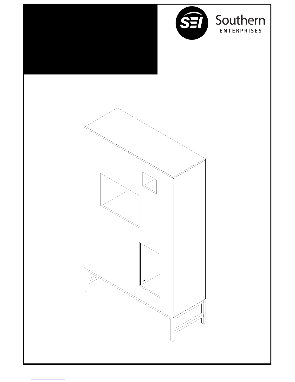
HZ1032A0TX/ HZ1032B0TX
Shadowbox Wine/Bar
Cabinet
Assembly Instructions
Due to weight, assembly requires two people.
Following detailed instructions, assembly should take approximately two hours.
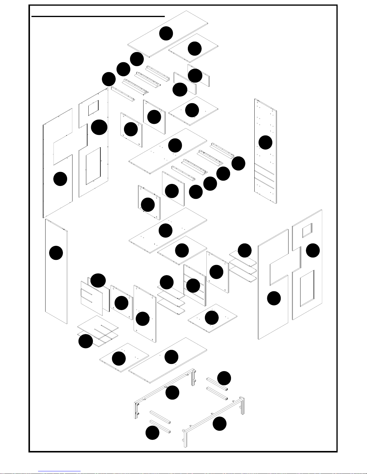
PACKAGE CONTENTS
2
A
W
V
M
S
T
S
S
T
T
S
O
D
O
L
N
P
J
G
U
F
C
J
J
K
E
Y
I
B
R
Z
Z
R
H
J
Q
Q
X
G
U
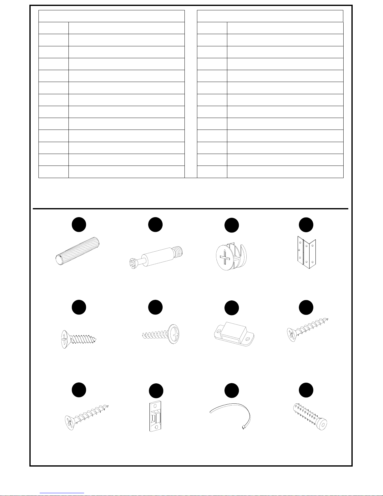
HARDWARE CONTENTS
PART DESCRIPTION QUANTITY
PART DESCRIPTION QUANTITY
A Top Panel 1 N Shelf 1
B Bottom Panel 1 O Vertical Panel 2
C Left Side Panel 1 P Vertical Panel 1
D Right Side Panel 1 Q Wine Rack Panel 4
E Shelf 1 R Leg 2
F Shelf 1 S Glass Rack Side 4
G Vertical Panel 2 T Glass Rack Middle 4
H Vertical Panel 1 U Wine Shelf 6
I Shelf 1 V Back Panel 1
J Vertical Panel 4 W Back Panel 1
K Shelf 1 X Left Door 1
L Shelf 1 Y Right Door 1
M Shelf 1 Z Metal Rail 4
3
1
Wood dowel
Qty:
92
2
Cam bolt
Qty:
68
3
Cam lock
Qty:
68
4
Hinge
Qty:
6
5
Screw 1/2” L
Qty: 42
6
Screw 1/2” L
Qty:
48
7
Magnet
Qty:
6
8
Screw 1-1/4” L
Qty:
24
9
Screw 1-3/8” L
Qty:
4
Bracket
Qty:
4
Plastic strap
Qty:
2
Anchor
Qty:
4
10
11
12
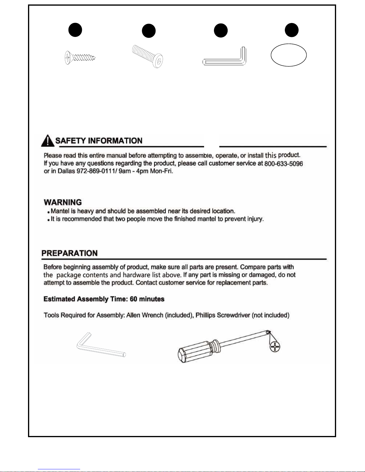
4
Screw 5/8” L
Qty: 4
Bolt 1/2”L
Qty:
14
Allen wrench
Qty:
1
Paper cover
Qty:
68
14
15
16
13
ASSEMBLY INSTRUCTIONS
HARDWARE USED
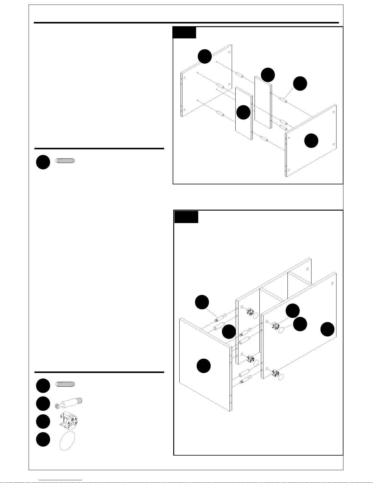
Wood Dowel x 8
HARDWARE USED
Wood Dowel x 4
Cam Bolt x 4
Cam Lock x 4
Paper Cover x 4
5
Wood may scratch easily, please
Be careful when assembling. Do not
scratch.
1. Attach shelf (M), vertical panels (O) and
shelf (N) by inserting wood dowels (1)
into holes.
2. Insert cam locks (3) into holes in
assembled unit on Figure 1.
Screw cam bolts (2) into holes on
vertical panel (P).
Attach vertical panel (P) to assembled
unit on Figure 1 by inserting wood
dowels (1) and cam bolts (2) into
corresponding holes until vertical panel
(P) and assembled unit on Figure 1
meet.
Tighten by rotating cam locks (3) in
clockwise direction with Phillips
screwdriver.
Cover cam lock holes with paper covers
(16).
1
2
1
1
2
3
16
M
N
O
O
1
1
2
3
16
P
N
ASSEMBLY INSTRUCTIONS
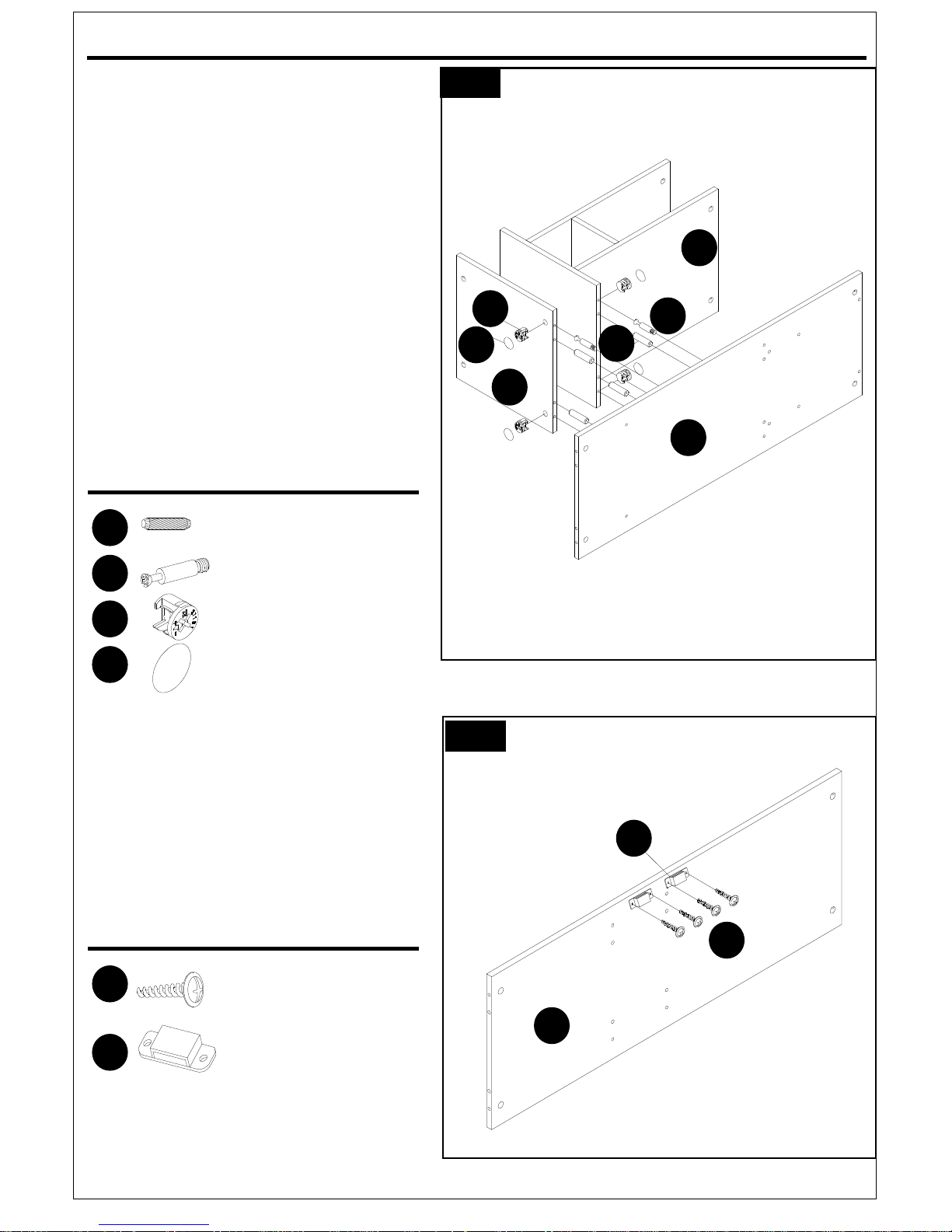
HARDWARE USED
Wood Dowel x 4
Cam Bolt x 4
Cam Lock x 4
Paper Cover x 4
HARDWARE USED
Screw 1/2” x 4
Magnet x 2
6
3. Insert cam locks (3) into corresponding
holes in assembled unit on Figure 2.
Screw cam bolts (2) into corresponding
holes on shelf (L). Attach shelf (L) to
assembled unit on Figure 2 by inserting
wood dowels (1) and cam bolts (2) into
corresponding holes until shelf panel (L)
and assembled unit meet.
Tighten by rotating cam locks (3) in
clockwise direction with Phillips
screwdriver.
Cover cam lock holes with paper covers
(16).
Make sure cam lock holes on shelf (L)
are facing down as shown on illustration.
4. Attach magnets (7) to shelf (K) using
screws (6).
Tighten screws with Phillips screwdriver.
3
4
6
7
1
2
3
16
1
2
3
16
L
J
N
7
6
K
 Loading...