

Page 1
EA-P1 Proximity Controller
Description
Default Value
Operating Instructions
Package Contents
Stand alone PIN + Prox Controller
Operating instructions
Wire harness for JA door access connector (9-wires with
blue connector)
Wire harness for JB lockout alarmconnector(8-wires with
white connector)
Wire harness for JC tamper switch connector(3-wires with
blue connector)
Wire harness for JD externalWiegand reader connector (4-
wires with white connector)
Diode (IN4007GW)
2 mounting screws
EA-P1-01x Standalone Proximity Controller
1
1
2
2
3
3
4
4
Specifications
User Cards Supported: 9,999
Supervisor Cards Supported: 9
PIN Codes Supported: 5
Power: 12VDC ± 10%
90mA maximum (standby mode), no
attached devices
110mA maximum (operating mode), no
attached devices
Transmit Frequency: 125kHz ASK (EM)
Card Reading Range: up to 10 cm (depending on installation)
Default Access Time: 4 seconds
Operating Temperature: 0-50 °C
Operating Humidity: 20-90% RH, No condensation
Dimensions: 118 mm x 75 mm x 19 mm
Default Settings
The table below describes the default settings of the EA-P1-01x
controller.
Access Time 4 seconds
PIN Code Length 4 digits
Number of Failed Attempts 3
Lockout Alarm Time 60 seconds
Mode of Operation card only
Enrolling Supervisor Card
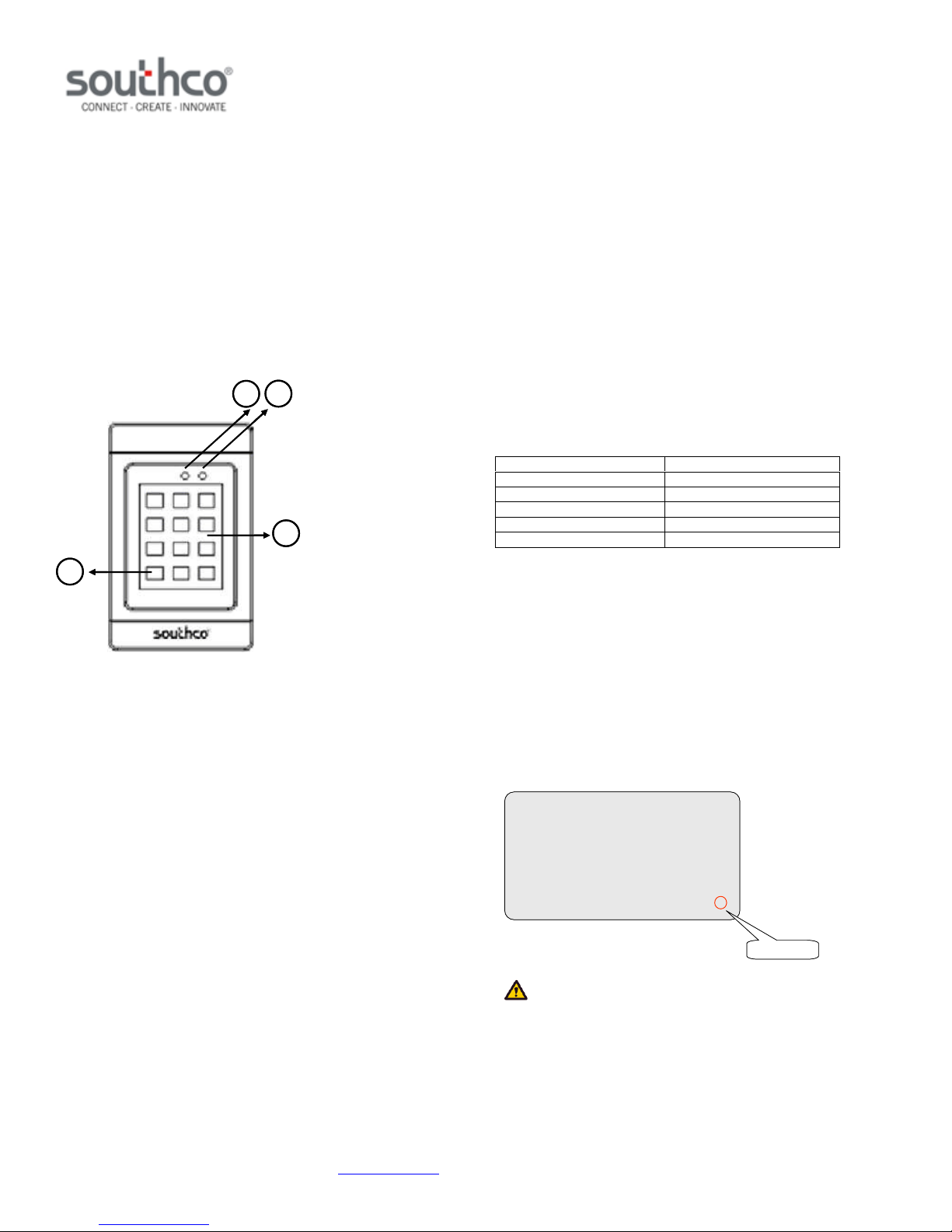
1. Power ON LED
2. Bicolor (red/green) Status LED
3. PIN + Prox Controller
4. Return to Ready State
Features
Supports up to 9,999 user cards and five PIN codes
Multiple modes of operation: card-only, card or PIN, card
and PIN, bypass mode
Programmable door release time(1to98seconds)
Programmable failed attempts (1 to99)
Programmable lockout time (1to 98 seconds)
Programmable user and supervisorcodelength (4 to 8
digits)
LED indicators: Power and Status
Supports connection to an external 26-bitWiegand reader
Non-volatile memory will retain data when power is removed
Tamper switch
For indoor use only
Controller Mounting and Installation
Please refer to Southco trade drawing J-EA-P1-01 for mounting and
installation details.
To enroll the supervisor card:
1. Apply power to the unit.
2. Switch the two DIP switches on the rear of the unit to “ON”.
3. Hold the supervisor card to the unit. The status LED will
flash red/green if the card has been successfully enrolled.
4. Switch the two DIP switches on the rear of the unit to their
original positions (“1” and “2”).
To enroll additional supervisor cards, repeat Steps 1-3 above. Note
that the last digit in the bottom right corner of the prox card must be
different for each supervisor card (see below).
xxxx xxxxxxxxxx 01234 56789
last digit
NOTE: Once a supervisor card has been enrolled, it cannot be
deleted.
J-EA-P1-01-M_revD visit www.southco.com for latest version of this document Page 1 of 4
Page 2

EA-P1 Proximity Controller
Operating Instructions
Enrolling User Cards
User cards can be enrolled individually or in blocks. To enroll an
individual user card:
1. Hold the supervisor card to the unit.
2. Enter 6-6-6-6 on the keypad.
3. Enter the last four digits on the bottom right corner of the
prox card to be enrolled (example below).
xxxx xxxxxxxxxx 01234 56789
last 4 digits
4. To enroll another card, repeat Step #3 while the status LED
is still green.
5. The unit will return to user mode when the status LED turns
off or if the ‘*’ (return-to-ready state) key is pressed.
To enroll a block of cards:
1. Hold the supervisor card to the unit.
2. Enter 6-6-0-0 on the keypad.
3. Enter the last four digits of the lowest card in the block to be
enrolled.
4. Enter the last four digits of the highest card in the block to be
enrolled.
5. The unit will return to user mode when the status LED turns
off or if the ‘*’ (return-to-ready state) key is pressed.
For example, entering 6-6-0-0 8-3-0-0 8-3-0-5 will enroll cards whose
last four digits range from 8300 to 8305.
To delete a block of cards:
1. Hold the supervisor card to the unit.
2. Enter 7-7-0-0 on the keypad.
3. Enter the last four digits of the lowest numbered card in the
block to be deleted.
4. Enter the last four digits of the highest numbered card in the
block to be deleted.
5. The unit will return to user mode when the status LED turns
off or if the ‘*’ (return-to-ready state) key is pressed.
For example, entering 7-7-0-0 8-3-0-0 8-3-0-5 will delete cards whose
last four digits range from 8300 to 8305.
Enrolling and Changing PIN Numbers
Five PIN numbers can be enrolled. The default PIN number length is
four digits. To enroll a PIN number:
1. Hold the supervisor card to the unit.
2. Enter 4-6-0-n on the keypad, where n is the slot number
(range 1-5).
3. Enter the desired four digit PIN number.
Deleting PIN Numbers
PIN numbers may be deleted either individually or all at once. To
delete an individual PIN number:
1. Hold the supervisor card to the unit.
2. Enter 4-7-0-n on the keypad, where n is the slot number
(range 1-5).
To delete all PIN numbers:
1. Hold the supervisor card to the unit.
2. Enter 4-7-0-0 on the keypad.
Changing PIN Number Length
Deleting User Cards
User cards can be deleted individually or in blocks. To delete an
individual user card:
1. Hold the supervisor card to the unit.
2. Enter 7-7-7-7 on the keypad.
3. Enter the last four digits on the bottom right corner of the
prox card to be deleted.
4. To delete another card, repeat Step #3 while the status LED
is still green.
5. The unit will return to user mode when the status LED turns
off or if the ‘*’ (return-to-ready state) key is pressed.
J-EA-P1-01-M_revD visit www.southco.com for latest version of this document Page 2 of 4
The default PIN number length is four digits. It can be programmed to
be four to eight digits. To change the PIN numberlength:
1. Hold the supervisor card to the unit.
2. Enter 4-8-0-d, where d is the number of digits in the PIN
number (range 1-8).
NOTE: Changing the PIN code length will not delete
programmed PIN numbers. Changing the PIN code length to be
longer than PIN numbers stored in memory will result in the PINs being
unusable. For example, if a four digit PIN is stored in memory, and the
PIN number length is then changed to eight, then the PIN cannot be
used.
However, if the PIN length is changed to be shorter than programmed
Page 3

EA-P1 Proximity Controller
Operating Instructions
PIN numbers already enrolled, then only the first d digits need to be
entered to be granted access, where d is the newly programmed PIN
code length. For example, if a four digit PIN has been programmed
and the PIN code length is later changed to three digits, only the first
three digits of the PIN need to be entered.
Setting the Mode of Operation
The unit can be set to one of four operating modes:
Card-Only: Access granted when a valid card is held to the
unit. This is the default mode.
Card and PIN: Access granted when a valid card is held to
the unit and then an enrolled PIN is entered.
Card or PIN: Access granted when either a valid card is
held to the unit or an enrolled PIN is entered.
Bypass: Access granted until bypass mode exit command is
issued.
To set the unit to operate in these modes:
Card-Only
1. Hold the supervisor card to the unit.
2. Enter 3-2-0-0 on the keypad.
Card and PIN
1. Hold the supervisor card to the unit.
2. Enter 3-3-0-0 on the keypad.
Card or PIN
1. Hold the supervisor card to the unit.
2. Enter 3-4-0-0 on the keypad.
Bypass Mode
1. Hold the supervisor card to the unit.
2. Enter 3-8-0-1 on the keypad to enter bypass mode (Enter 38-0-0 to exit bypass mode)
NOTE: In all modes, access will be granted if the supervisor card is
held to the unit and 3-6-0-1 is entered on the keypad.
Changing Number of Failed Attempts
The default number of failed attempts is three. To change the number
of failed attempts:
1. Hold the supervisor card to the unit.
2. Enter 2-4-nn on the keypad, where nn is the desired number
of failed attempts (range 01-99)
Unless a valid user card is presented to the controller, the controller
will assert the lockout alarm on the next failed attempt.
Resetting the Unit
Resetting the unit will restore the factory settings. It will not delete PIN
numbers or enrolled user and supervisor cards. To reset the unit:
1. Hold the supervisor card to the unit.
2. Enter 0-8-0-0 on the keypad.
Auxiliary Input
The EA-P1-01x controller has an auxiliary input that can be connected
to a momentary push-button. Pin 6 from the JA connector (green wire)
is the auxiliary input. When the auxiliary input is 12VDC, the controller
will grant access while the input is asserted plus theprogrammed
access time. Connect a momentary push-button switch between the
input lead and a 12VDC source to use this feature. NOTE: The unit
will beep while the input is asserted.
Lockout Alarm (JB Connector)
The EA-P1-01x controller provides a relay output that is activated
when the keypad is locked out due to reaching the number of allowed
failed attempts. This will cause the relay to close (i.e. drive the voltage
at the COM terminal) for the programmed keypad lockout time.
Tamper Switch (JC Connector)
Changing Door Access Time
The default door access time is four seconds. To change the access
time:
1. Hold the supervisor card to the unit.
2. Enter 2-1-tt on the keypad, where tt is the desired door
access time in seconds (range 01-98).
NOTE: If 2199 is entered, the unit will allow access until a valid
card/PIN is entered.
Changing Lockout Alarm Time
The default door access time is sixty seconds. To change the access
time:
1. Hold the supervisor card to the unit.
2. Enter 2-2-tt on the keypad, where tt is the desired lockout
alarm time in seconds (range 01-98).
NOTE: If 2299 is entered, the unit will continue to assert the lockout
alarm until a valid card/PIN is entered.
J-EA-P1-01-M_revD visit www.southco.com for latest version of this document Page 3 of 4
The JC connector can be used to monitor the status of the tamper
switch. When the tamper switch is closed, the NO signal will be driven
to the same voltage level as the COM signal. When the tamper switch
is open, the NC signal will be driven to the same voltage level as the
COM signal. See Wiring Diagram for pinout.
Connecting to Wiegand Reader (JD Connector)
The JD connector can be used to connect a 26-bit Wiegand reader to
the EA-P1-01x. Supervisor and user cards do not need to be reenrolled to work with the Wiegand reader. NOTE: Only readers that
provide a 26-bit Wiegand output are supported. See Wiring Diagram
for pinout.
Page 4
EA-P1 Proximity Controller
MARK
Operating Instructions
Wiring Multiple Controllers
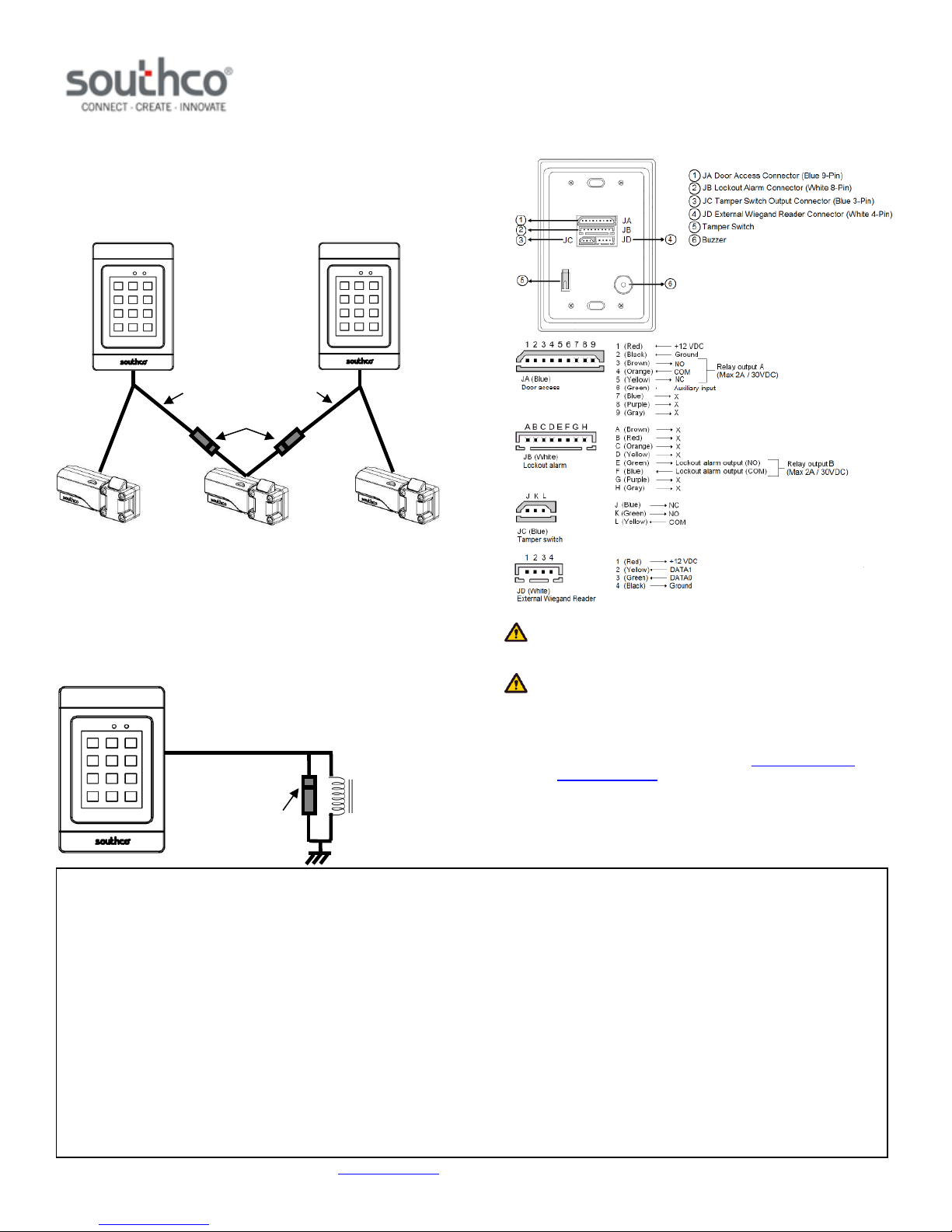
A diode is provided with the EA-P1-01x controller. The diode allows
for a keypad to be isolated when multiple controllers are connected to
the same latch. Refer to the figure below for wiring details when using
the diode when using multiple controllers. Observe proper polarity
when connecting the diode.
NORMALLY OPEN (BROWN WIRE) OUTPUT, OR
NORMALLY CLOSED (YELLOW WIRE) OUTPUT
DIODE POLARITY
Connecting to an Inductive Load
Wiring Diagram
A diode is provided with the EA-P1-01x controller. This diode should
be used when connecting to a device with an inductive load (for
example, a relay or door strike) to protect the controller from a reverse
voltage spike. The diode should be placed in parallel with the coil, as
shown in the figure below. Observe proper polarity when connecting
the diode.
CAUTION: Product can be damaged if wired incorrectly. Follow
wiring diagram above.
CAUTION: A controller that has been programmed is nonreturnable. Please use caution in programming functions so as not to
render the keypad unusable.
NORMALLY OPEN (BROWN WIRE) OUTPUT, OR
NORMALLY CLOSED (YELLOW WIRE) OUTPUT
For technical support of this product contact: [email protected]
or visit: www.southco.com
DIODE
POLARITY
MARK
This equipment has been tested and found to comply with the limits for a class B digital device, pursuant to part 15 of the FCC rules. These limits
are designed to provide reasonable protection against harmful interference in a residential installation. This equipment generates, uses and can
radiate radio frequency energy and, if not installed and used in accordance with the installation, may cause harmful interference to radio
communication. However, there is no guarantee that interference will not occur in a particular installation. If this equipment does cause harmful
interference to radio or television reception, which can be determined by turning the equipment off and on, the user is encouraged to try to correct
the interference by one or more of the following measures:
Reorient or relocate the receiving antenna
Increase the separation between the equipment and receiver
Connect the equipment into an outlet on a circuit different from that to which the receiver is connected
Consult the dealer or an experienced radio / TV technician for help
You are cautioned that changes or modifications not expressly approved by the party responsible for compliance could void your authority to
operate the equipment.
This device complies with part 15 of the FCC rules. Operation is subject to the following two conditions:
1) This device may not cause harmful interference and
2) This device must accept any interference received, including interference that may cause undesired operation.
J-EA-P1-01-M_revD visit www.southco.com for latest version of this document Page 4 of 4
 Loading...