

Page 1
Page 2
Page 3
Sdfsfsdfsfdsafsafsdfsff EA-KC2-201 Membrane Keypad Controller
Supervisor Code
7183
Door Release Time
10 seconds
Latch Power Mode
Off
Instructions for Programming EA-KC2-201
Package Contents
EA-KC2-201 Controller
Instruction guide
EA-KC2-201 Keypad Access Controller
Features
Two independent outputs
Supports 120 user access codes per output
4 digit key codes
Programmable latch release time (1 sec to over 100 mins) ± 1%
LED indicators (applies to membrane keypad)
Non-volatile memory will retain user/supervisor codes and door
release time setting when power is removed
Low power for battery applications
Specifications
Access Code Length: 4 digits
Supply Voltage: 12V - 24VDC ± 10% (NOTE: Do not
exceed maximum latch operating voltage)
Standby Current: 30A (max, no attached devices)
Operating Current: 10mA (max, no attached devices)
Max Latch Current: 2A peak (each)
NOTE: For indoor use only.
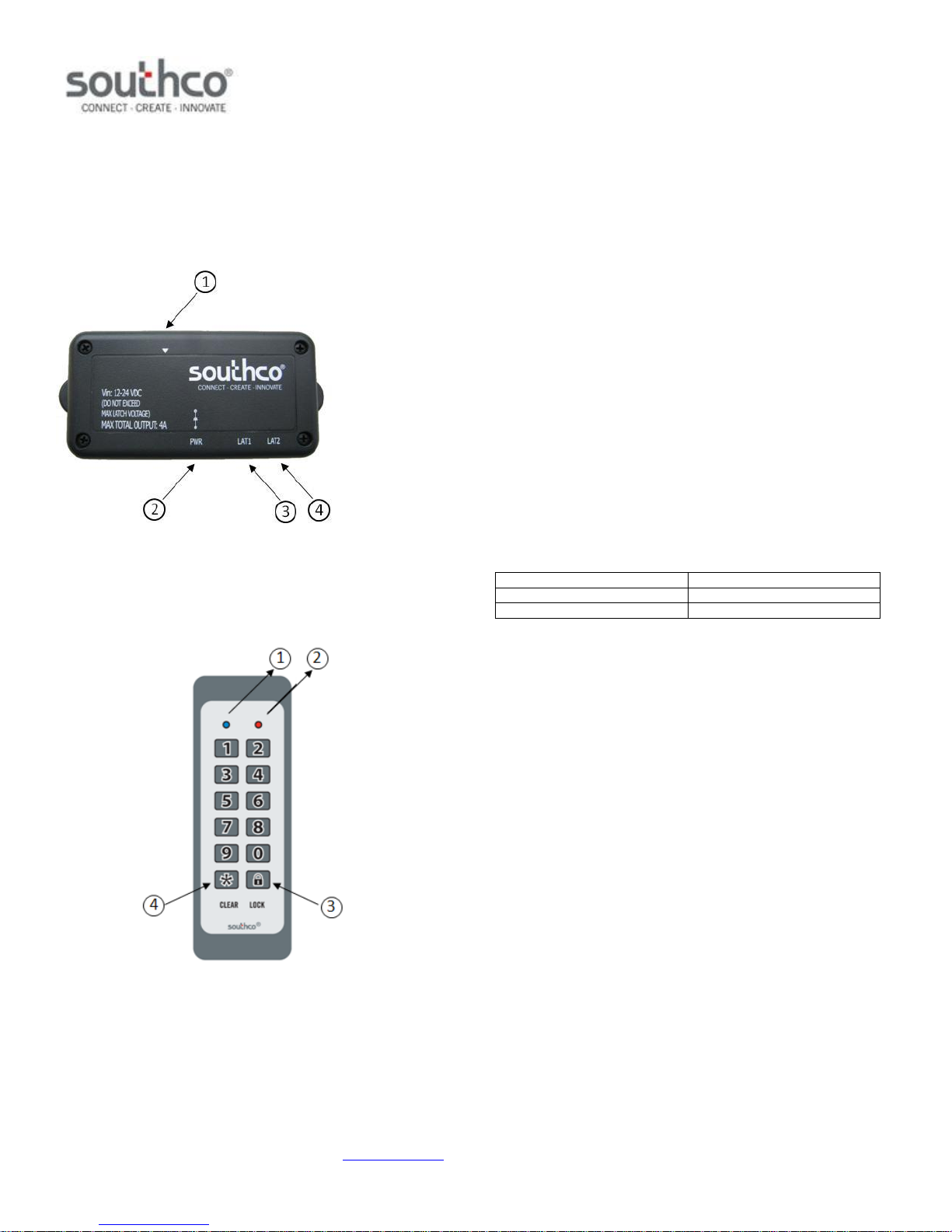
1. Membrane Keypad Connector
2. Power Supply Connector
3. Latch Output 1 Connector
Default Settings
4. Latch Output 2 Connector
EA-KC2-102 Membrane Keypad (order separately)
Normal Operation
In normal operation the user will enter a 4 digit access code. Once a
numeric key is pressed, the blue Status LED will light. The user will then
enter the remaining 3 digits of their code. If the access code is accepted,
the blue Status LED will blink and the door latch will be released for the
time period specified. If the code is not accepted, the red Status LED will
blink. If a mistake is made during code entry, the ‘*’ key can be used to
clear previous key strokes and start over. This will also turn off the blue
Status LED. Once a key is pressed, the keypad will wait 30 seconds for
the next input. If thirty seconds elapse with no input, the keypad will clear
previous key strokes, shut off the blue Status LED, blink the red Status
LED and return to sleep mode.
1. Blue Status LED – indicates accepted command or controller
waiting for input
2. Red Status LED – indicates incorrect input or timeout
3. “Lock” Key -- re-locks doors during access time
4. “Clear” Key – clears previous keystrokes
J-EA-KC2-201-M_revB visit www.southco.com for latest version of this document Page 1 of 3
Page 4
Sdfsfsdfsfdsafsafsdfsff EA-KC2-201 Membrane Keypad Controller
Programming
Code
Description
0 *
Restore Default Settings
1 *
Erase all User Access Codes – Latch Output 1
2 *
Erase all User Access Codes – Latch Output 2
3 *
Remove a Specific User Code
4 *
Add User Access Code – Latch Output 1
5 *
Add User Access Code – Latch Output 2
6 *
Program Door Release Time
7 *
Program New Supervisor Code
8 *
Latch Power Mode
(will default to off, if power is removed)
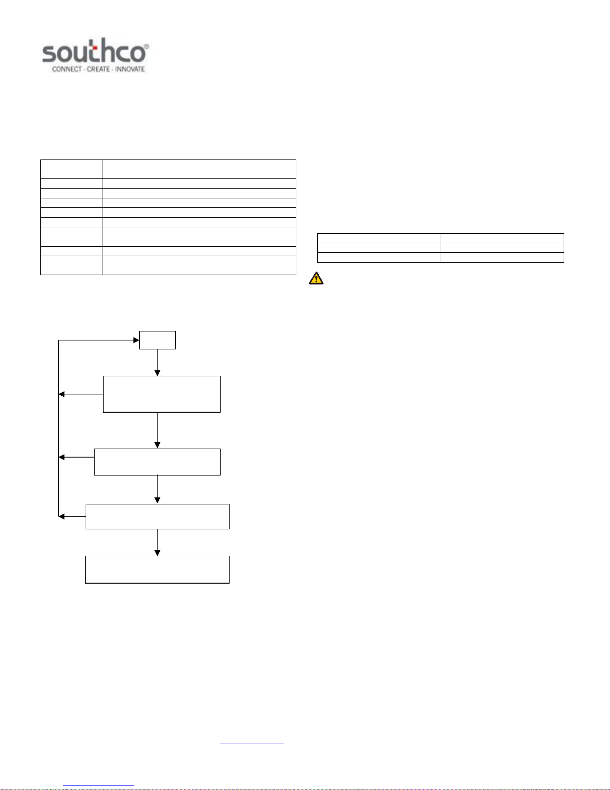
Press the ‘*’ key, then enter
the 4 digit supervisor code
followed by the ‘*’ key
The blue Status LED will flash
indicating programming is complete
Start
If incorrect, the red
Status LED will flash
If incorrect, the red
Status LED will flash
Accepted
Enter new supervisor code, user
access code, or door release time
If accepted, the blue
Status LED will turn on
If accepted, the blue Status
LED will flash twice
If incorrect, the red
Status LED will flash
Enter the programming code
Supervisor Code
7183
Door Release Time
10 seconds
Latch Power Mode
Off
Instructions for Programming EA-KC2-201
Programming the Keypad
All programming functions are initiated by entering the ‘*’ key, then the
supervisor code, followed by the ‘*’ key. Next, the programming code is
entered. See the table below for programming codes.
Programming Codes
0 * : Restore Defaults
The controller can be set to its factory default settings. To restore the
default settings:
1. Press the ‘*’ key, then enter the 4 digit supervisor code followed
by the ‘*’ key. The blue status LED will light.
2. Press the ‘0’ key, followed by the ‘*’ key.
The blue Status LED will flash indicating that programming is complete.
The table below lists the default parameters.
Programming Flowchart
NOTE: Restoring the default settings will also erase all user codes.
1 * & 2 * : Erase All User Access Codes by Latch Output
1. Press the ‘*’ key, then enter the 4 digit supervisor code followed
by the ‘*’ key. The blue status LED will light.
2. Press the ‘1’ (for Latch Output 1) or ‘2’ (for Latch Output 2) key,
followed by the ‘*’ key.
The blue Status LED will flash indicating that erasing is complete.
3 * : Remove a Specific User Access Code
1. Press the ‘*’ key, then enter the 4 digit supervisor code followed
by the ‘*’ key. The blue status LED will light.
2. Press the ‘3’ key, followed by the ‘*’ key.
3. Enter the four digit user access code to be removed.
The blue Status LED will flash indicating that erasing is complete. If the
user access code has been assigned to both outputs, then the user access
code will be removed from both outputs.
If the user access code is not stored in memory, or an invalid key is
pressed (‘*’, ‘Lock’) the red status LED will flash.
Once a programming code or supervisor code has been accepted, the
keypad will wait 30 seconds for the next key input. If thirty seconds elapse
with no input, the red Status LED will flash and the keypad will return to
sleep mode.
4 * & 5 * : Add User Access Code by Latch Output
120 user access codes can be programmed into each latch output. The
user access codes can be any combination of four digits. To program a
user access code:
1. Press the ‘*’ key, then enter the 4 digit supervisor code followed
by the ‘*’ key. The blue status LED will light.
2. Press the ‘4’ (for Latch Output 1 ) or ‘5’ (for Latch Output 2) key,
followed by the ‘*’ key.
3. Enter the four digit user access code desired.
J-EA-KC2-201-M_revB visit www.southco.com for latest version of this document Page 2 of 3
Page 5
Sdfsfsdfsfdsafsafsdfsff EA-KC2-201 Membrane Keypad Controller
Pin #
Description
Note
1
V
GND
ground
2
V
SUPPLY
power supply output to latch
3
V
GND
ground
4
Control Signal
door release command output
5
N/C
no connection
6
N/C
no connection
PIN 1
PIN 2
PIN 4
PIN 3
FCC Compliance Statement
This equipment has been tested and found to comply with the limits for a Class B digital device, pursuant to part 15 of the FCC Rules. These limits
are designed to provide reasonable protection against harmful interference when the equipment is operated in a commercial environment. This
equipment generates, uses, and can radiate radio frequency energy and, if not installed and used in accordance with the instruction manual, may
cause harmful interference to radio communications. Operation of this equipment in a residential area is likely to cause harmful interference in
which case the user will be required to correct the interference at his own expense.
Industry Canada Compliance Statement
This Class B digital apparatus complies with Canadian ICES-003.
CET appareil numérique de la classe B est conforme á la norme NMB-003 du Canada.
For technical support of this product contact: [email protected] or visit www.southco.com.
Instructions for Programming EA-KC2-201
The blue Status LED will flash indicating that programming is complete.
Programming the same user access code to both latch outputs will allow
that user access code to open both latches simultaneously.
If the user memory is full or an invalid key is pressed (‘*’, ‘Lock’), the red
status LED will flash. If the code entered is already stored in memory, the
blue status LED will flash.
6 * : Program Door Release Time
The length of time the latch(es) are released can be programmed from 1
second to 100 minutes and 39 seconds. To change from the default of ten
seconds:
1. Press the ‘*’ key, then enter the 4 digit supervisor code followed
by the ‘*’ key. The blue status LED will light.
2. Press the ‘6’ key, followed by the ‘*’ key.
3. Enter the desired amount of time in the format ‘MMSS’ where
MM is the number of minutes and SS is the number of seconds.
The blue Status LED will flash indicating programming is complete. If an
invalid key is pressed (‘*’, ‘Lock’), the red status LED will flash.
NOTE: The programmed door release time must be greater than the
connected latch’s cycle time.
Latch Power Mode is disabled by default. To enable this mode:
1. Press the ‘*’ key, then enter the 4 digit supervisor code followed
by the ‘*’ key. The blue status LED will light.
2. Press the ‘8’ key, followed by the ‘*’ key.
The blue Status LED will flash indicating that programming is complete. If
an invalid key is pressed (‘*’, ‘Lock’), the red status LED will flash.
This mode can be toggled on and off by entering this programming code
again.
NOTE: Latch Power Mode will be disabled if power is removed from
the controller.
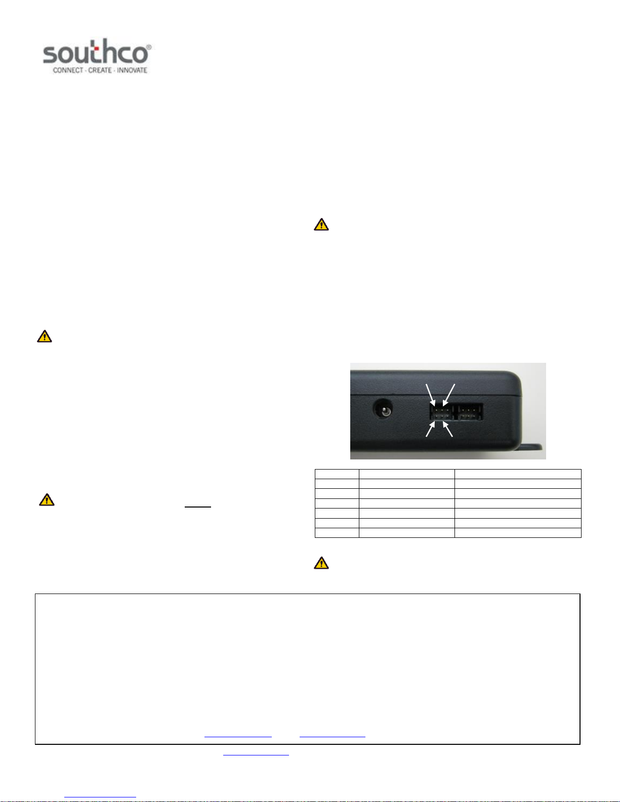
Latch Connector Pin Assignment
The controller’s latch output connectors provide a power supply and
command output for the electromechanical latches. These will be the
same voltage level as the controller’s power supply voltage (12 to 24VDC).
The controller’s power supply input must not exceed the electrical
ratings of the latch(es).
The figure and table below show the pinout of the latch output connectors.
7 * : Program New Supervisor Code
The supervisor code can be changed from its default setting (7183) to a
different 4 digit code. To change the supervisor code:
1. Press the ‘*’ key, then enter the 4 digit supervisor code followed
by the ‘*’ key. The blue status LED will light.
2. Press the ‘7’ key, followed by the ‘*’ key.
3. Enter the new four digit supervisor code.
The blue Status LED will flash indicating that programming is complete. If
an invalid key is pressed (‘*’, ‘Lock’), the red status LED will flash.
WARNING: The supervisor code cannot be recovered if lost or
forgotten. Store the supervisor code in a secure place.
8 * : Latch Power Mode
Enabling this mode will provide constant power to both latches. This is
required if the connected latch has a feature that requires constant power
(e.g. Southco’s H3-EM Electronic Locking Swinghandle’s status LED).
CAUTION: A keypad that has been programmed is non-returnable.
Please use caution in programming functions so as not to render the
keypad unusable.
J-EA-KC2-201-M_revB visit www.southco.com for latest version of this document Page 3 of 3
 Loading...