

Page 1
IMPORTANT FOR FUTURE REFERENCE
Please complete this information and retain this
manual for the life of the equi pment:
Model #: __________________________
Serial #: __________________________
Date Purchased: ___________________
OPERATOR’S MANUAL
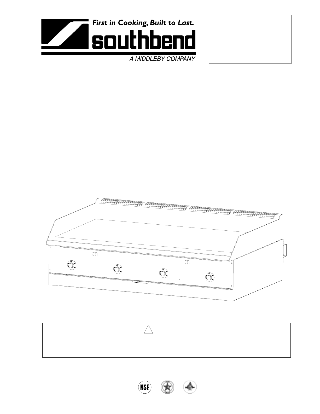
Counter Griddle
Model Numbers
SGS-24 SGS-24E
SGS-36 SGS-36E
SGS-48 SGS-48E
SGS-60 SGS-60E
Model SGS-48 Shown
! WARNING
Improper installation, adjustment, alteration, service or maintenance can cause property damage,
injury or death. Read the installation, operating and maintenance instructions thoroughly before
installing or servicing this equipment.
1100 Old Honeycutt Road, Fuquay-Varina, NC 27526
(800) 348-2558 or (919) 552-9161 • FAX (800) 348-2558 or (919) 552-9798
MANUAL 1182629 REV 2
$9.00
COUNTER GRIDDLE
MANUAL SECTION BR
Page 2
COUNTER GRIDDLE
SAFETY PRECAUTIONS
Before installing a nd opera ting this equipm ent, be sure e ver yone invol ved in its operat ion is f ully tr ained and
aware of precautions. Accidents and problems can be caused b y failure to follow fundamental rules and
precautions.
The following s ymbols, found throughout this manual, alert you to potentially dangerous conditions to the
operator, service personnel, or to the equipment.
! DANGER
! WARNING
! CAUTION
NOTICE
This symbol warns of immediate hazards that will result in severe injury or
death.
This symbol refers to a potential hazard or unsafe practice that could result in
injury or death.
This symbol refers to a potential hazard or unsafe practice that could result in
injury, product damage, or property damage.
This symbol refers to information that needs special attention or must be fully
understood, even though not dangerous.
! WARNING
FIRE HAZARD
FOR YOUR SAFETY
Do not store or use ga soline or other flamm able vapors and l iquids in the vicinit y of this or an y other
appliance.
Keep area around appliances free and clear of combustibles.
Purchaser of equipment m ust post in a prom inent location, detailed instruct ions to be follo wed in the
event the operator smells gas. Obtain the instructions from the local gas supplier.
! WARNING
Asphyxiation can result from improper ventilation. Do not obstruct the flow of combustion and
ventilation air to and from your cooking equipment.
NOTICE
Be sure this Operator’s Man ual and important papers ar e given to the proper authorit y to retain for
future reference.
NOTICE
This product is intended for commercial use only. NOT FOR HOUSEHOLD USE.
PAGE 2OPERATOR’S MANUAL 1182629 REV 2
Page 3
COUNTER GRIDDLE TABLE OF CONTENTS
Congratulations! You have purchased one of the finest pieces of commercial cooking equipment on the
market.
You will find that your new equipm ent, like all Southbend equipment, has been desig ned and m anufactured
to meet the toughest standards in t he industr y. Each piece of Southbend e quipment is carefull y engineered
and designs are verified through laboratory tests and field installations. With proper care and field
maintenance, you will experience years of reliable, trouble-free operation. For best results, read this
manual carefully.
RETAIN THIS MANUAL FOR FUTURE REFERENCE.
Table of Contents
Specifications..........................................................................................................................4
Installation...............................................................................................................................7
Operation ..............................................................................................................................19
Cleaning................................................................................................................................21
Adjustments ..........................................................................................................................22
Troubleshooting ....................................................................................................................26
Parts......................................................................................................................................27
Read these instructions carefully before attempting installation. Installation and initial startup should be
performed by a qualified installer. Unless the installation instructions for this product are followed by a
qualified service tech nician (a person experienced in and knowledge able with the insta llation of comm ercial
gas an/or electric cooking equipm ent) then the terms and conditi ons on the Ma nufactur er’s Lim ited W arranty
will be rendered void and no warranty of any kind shall apply.
In the event you have questions concerning the installation, use, care, or service of the product, write to:
Technical Service Department
Southbend
1100 Old Honeycutt Road
Fuquay-Varina, North Carolina 27526 USA
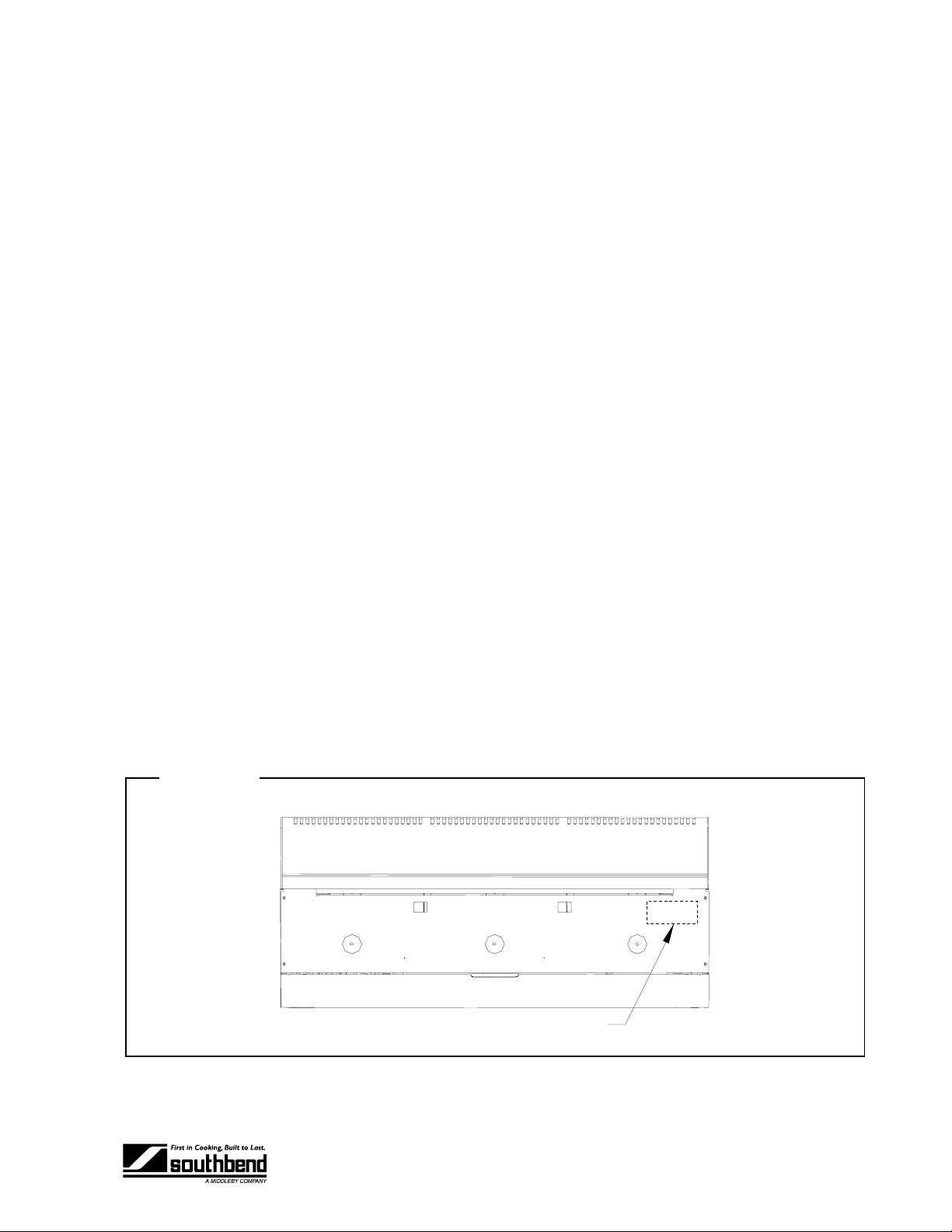
The serial plate is located on the interior side of the upper front panel, as shown below:
Figure 1
Serial plate is located on the inside of this panel.
OPERATOR’S MANUAL 1182629 REV 2PAGE 3
Model SGS-36 Shown
Page 4

SPECIFICATIONS COUNTER GRIDDLE
SPECIFICATIONS
SPECIFICATIONS
NOTICE
Installation must comply with National Fuel Gas Code, ANSI Z 223.1, Natural G as Installation Code,
CAN/CGA-B149.1, or the Propane Installation Code, CAN/CGA-B149.2, as applicable.
Local codes regarding install ati on vary greatly from one ar ea t o an oth er . T he Nat ion al Fire Protection
Association, Inc. states in its NFPA 96 latest edition that local codes are the “authority having
jurisdiction” when it com es to insta llation req uirem ents for equ ipment. T herefore, install ations s hould
comply with all local codes.
Southbend reserves the right to change specifications and product design without notice. Such
revisions do not e ntitle the bu yer to c orres pondi ng cha nges, add it ions, or rep lacem ents f or previo usl y
purchased equipment.
This product is intended for commercial use only, not for household use.
GAS SUPPLY
The Serial Plate is located on the int erior side of the upper f ront panel ( see Figur e 1 on p age 3). It indicates
the type of gas (propane or natural gas) the griddle is equipped to burn. All Southbend equipment is
adjusted at the factory. Check type of gas on serial plate.
This appliance should be connected ONLY to the type of gas for which it is configured.
An adequate gas supply is imperative. Undersized or low pressure lines will restrict the volume of gas
required for satisf ac tor y perf ormance. Fluctuations of more than 25% on natur al gas or 10% on propa ne gas
will create problems and affect burner operating characteristics. A 1/8” pressure tap is located on the
manifold to measure the manifold pressure.
No segment of the gas supply line to the griddle should be smaller than the inside diameter of the inlet
connector of the griddle (3/4" NPT).
Purge the supply line to clean out dust, dirt, or other foreign matter before connecting the line to the griddle.
All pipe joints and connections must be tested t horoughl y for gas le aks. Use only soap y water for tes ting on
all gases. NEVER use an open flame to c heck for gas leaks. All con nections must be checked f or leaks
after the griddle has been put into operation. Test pressure should not exceed 14” W.C.
! CAUTION
THIS APPLIANCE AND ITS INDIVIDUAL SHUTOFF VALVE MUST BE DISCONNECTED FROM
THE GAS SUPPLY PIPING SYST EM DURING ANY PRESSURE TESTING OF THAT SYSTEM AT
TEST PRESSURES IN EXCESS OF 1/2 PSIG (3.45 kPa).
THIS APPLIANCE MUST BE ISOLATED FRO M THE GAS SUPP LY PI PING SYST EM BY C LOSING
ITS INDIVIDUAL MANUAL SHUTOFF V ALVE DURING ANY PRESSURE TESTING OF THE GAS
SUPPLY PIPING SYSTEM AT TEST PRESSURES EQUAL TO OR LESS THAN 1/2 PSIG (3.45
kPa).
PAGE 4OPERATOR’S MANUAL 1182629 REV 2
Page 5
COUNTER GRIDDLE SPECIFICATIONS
CLEARANCES
!
WARNING
There must be adequate clearance between griddles and adjacent construction. C learance in the
front must also be provided for servicing and for operation.
Minimum clearances from COMBUSTIBLE construction are 12" on sides, 8" on rear, and 4" on
bottom (order the countertop legs or floor stand).
Minimum clearances from NON-COMBUST IBLE construction is 0" on sides, 2" on rear ( the 2" deep
stand-offs on the rear may be against a wall), and 0" on the bottom.
VENTILATION
!
WARNING
Improper ventilati on can result in person al injur y or death. Vent ilation whic h fails to pr operly re move
flue products can cause headaches, drowsiness, nausea, or could result in death.
All griddles m ust be install ed in such a m anner that the f low of combustion and ve nt ilation air ar e not
obstructed. Provisions for adequate air supply must be provided. Do not obstruct th e rear of the
griddle at as combustion air enters through this area.
SPECIFICATIONS
NOTICE
Proper ventilation is the owner ’s responsibility. Any problem due to improper ventilatio n will not be
covered by the warranty.
Air for combustion enters the rear of the griddle. The exhaust flue runs along the top rear edge.
Southbend recommends that a ventil ati on ca nopy extend 6" past the edg es of the gr iddle and be loca ted 6'6 "
above the floor.
If a wall exhaust fan is installed in t he wall behind t he griddle , it should be a t least two f eet above the t op of
the flue opening along the back edge of the griddle.
To avoid a negative pressure condit ion, return air must be br ought into the room to reple nish the air being
removed by the ventilation exhaust fan. RETURN-AIR FANS MUST NOT BLOW DOWN INTO THE
GRIDDLE FLUE (ALONG THE TOP REAR EDGE OF THE GRIDDLE), NOR DIRECTLY ONTO THE
GRIDDLE SURFACE.
Ventilation filters should be i nstalled at an an gle of 45° or mor e from the horizontal. T his prevents dripp ing
grease and facilitates collecting the run-off grease in a drip pan, usually installed with a filter.
Be sure to inspect and clean the ventilation system according to the ventilation equipment manufacturer ’s
instructions.
In case of unsatisf actor y perf orm ance on an y appli ance, ch eck the app liance with the vent ilatio n ex haus t f an
in the “OFF” position. D o th is on l y long eno ugh to check equipment perform ance. Then turn the fan back on
and let it run to remove any exhaust that may have accumulated during the test.
OPERATOR’S MANUAL 1182629 REV 2PAGE 5
Page 6
SPECIFICATIONS COUNTER GRIDDLE
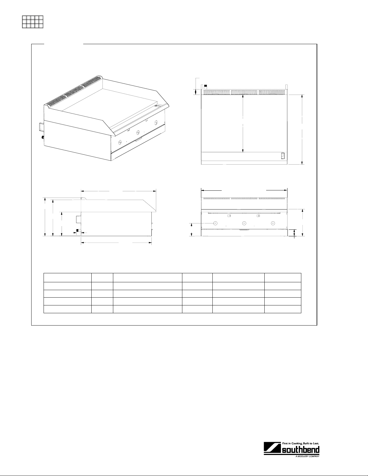
Figure 2
DIMENSIONS
SPECIFICATIONS
31.32"
16.00"
15.10"
9.96"
2.00"
29.42"
2.24"
24.00"
29.08"
Top View
Width (see table below)
11.24"
5.34"
2.78"
Front ViewSide View
Model Width Number and Size of Burners Total BTU Crate Size Crated Weight
SGS-24 & SGS-24E 24" 2 @ 30,000 60,000 31"W x 39"D x 24"H 305 lbs.
SGS-36 & SGS-36E 36" 3 @ 30,000 90,000 55"W x 39"D x 24"H 445 lbs.
SGS-48 & SGS-48E 48" 4 @ 30,000 120,000 55"W x 39"D x 24"H 545 lbs.
SGS-60 & SGS-60E 60" 5 @ 30,000 150,000 67"W x 39"D x 24"H 705 lbs.
CONSTRUCTION
The front, sides, and 5 " riser are all s tainless steel. T he rear and bottom panels ar e aluminized steel. T he
reinforced double-wall sides are fully insulated.
The griddle surface is high-c arbon, 1" thick , polished s teel plat ed with tr ivalent chr omium . The c hrome plate
has an emissivity rating of approximately 0.08.
Each foot of griddle width is heated by a U-shaped burner controlled by a thermostatic gas valve for
independent temperature control. Each pilot is equipped with a flame failure safety device.
The base of a 60" griddle consists of the base of a 24" griddle and a 36" griddle connected together,
spanned by a 60" griddle surface with one greas e duct and one gr eas e dra wer.
PAGE 6OPERATOR’S MANUAL 1182629 REV 2
Page 7

COUNTER GRIDDLE INSTALLATION
INSTALLATION
NOTICE
Installation must comply with National Fuel Gas Code, ANSI Z223.1, Natura l Gas Installation Code,
CAN/CGA-B149.1, or the Propane Installation Code, CAN/CGA-B149.2, as applicable.
These installation procedures must be followed by qualified personnel or warranty will be void.
Local codes regarding install ati on vary greatly from one ar ea t o an oth er . T he Nat ion al Fire Protection
Association, Inc. states in its NFPA 96 latest edition that local codes are the “authority having
jurisdiction” when it com es to insta llation req uirem ents for equ ipment. T herefore, install ations s hould
comply with all local codes.
Step 1: Unpack
IMMEDIATELY INSPECT FOR SHIPPING DAMAGE
All containers shou ld be examined f or damage before an d during unloading. The freight carri er has
assumed responsibility for its safe transit and delivery. If damaged equipment is received, either
apparent or concealed, a claim must be made with the delivering carrier.
Apparent damage or l os s must be noted on the f r eight b i ll at t he t ime of delivery. T he f reight bill must
then be signed by the c arrier representat ive (Driver). If the bill is not s igned, the car rier may ref use
the claim. The carrier can supply the necessary forms.
A request for insp ection must be m ade to the carrier within 15 da ys if there is concea led damage or
loss that is not apparent until after the equipment is uncrated. The carrier should arrange an
inspection. Be certain to hold all contents plus all packing material.
INSTALLATION
1. Uncrate carefully. Report any hidden damage to the freight carrier IMMEDIATELY.
2. Do not remove any tags or labels until griddle is installed and working properly.
Step 2: Attach Countertop Legs, Mount on Counter, or Mount on Stand
The counter griddle can be mounted in several ways:
To mount it on short, countertop legs, go to Step 2a on page 8.
To mount it directly on a countertop, go to Step 2b on page 9.
To mount it on an insulated base on a countertop, go to Step 2c on page 10.
To mount it on a stand that rests on the floor, go eit her to Step 2d on p age 11 (for 24", 36", and 48"
models) or to Step 2e on page 13 (for a 60" model).
OPERATOR’S MANUAL 1182629 REV 2PAGE 7
Page 8
INSTALLATION COUNTER GRIDDLE
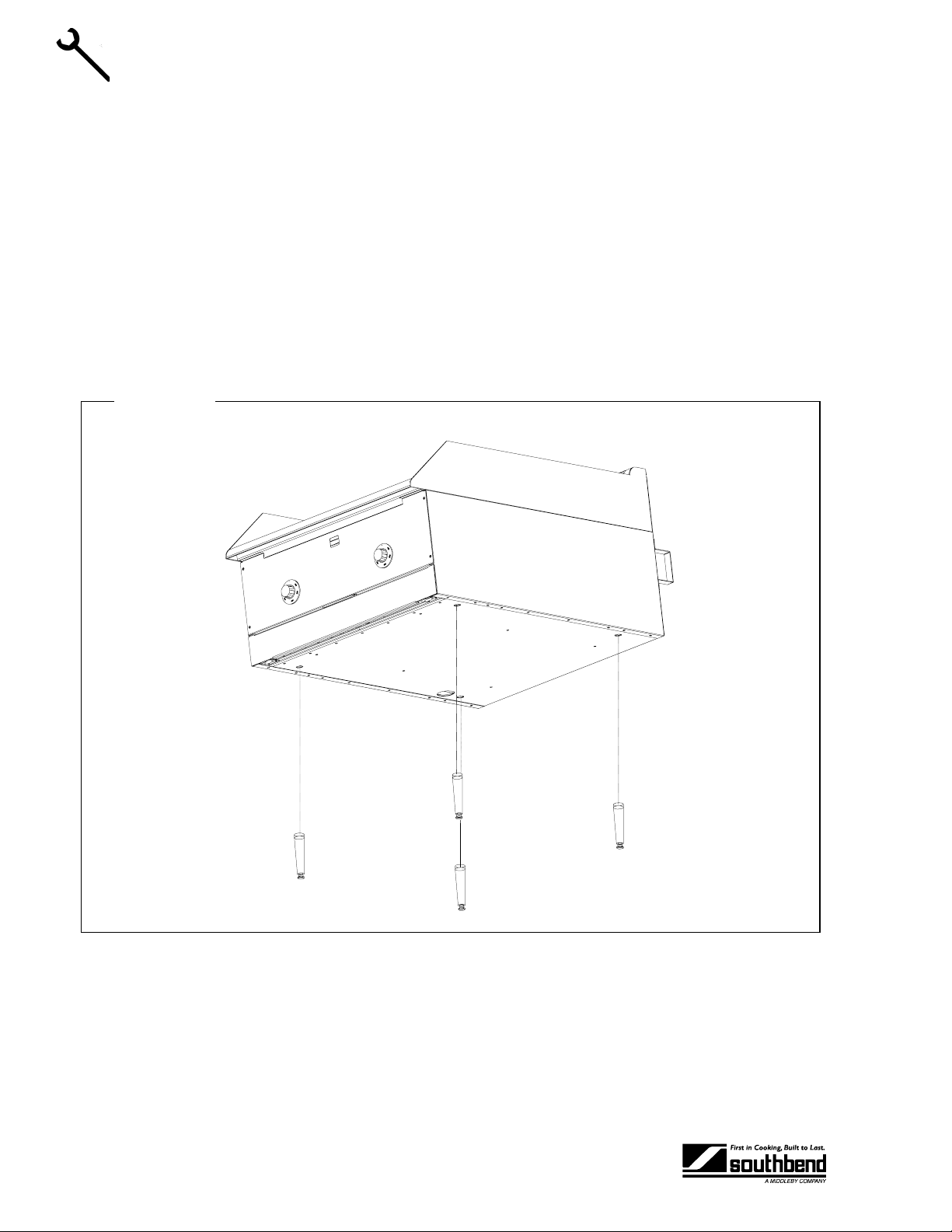
Step 2a: Installation on Countertop Legs
To install the griddle using countertop legs, do the following:
1. Locate the box of four legs shipped with the griddle (if countertop legs were ordered).
2. Raise the griddle about 6" so that the legs can be sc rewed into the bottom near the cor ners. Lift the
griddle only from the ends, never from the middle! Support th e lifted gridd le so that it will not f all while
you are attaching the legs.
3. Screw the four legs into the thr eaded holes located on the bott om of the griddle near each corner (as
shown in Figure 3 below).
4. Gently lower the grid dle onto the counter. Level the grid dle surf ace b y screwing o ne or m ore of the legs
INSTALLATION
in or out.
5. Go on to Step 4 on page 16.
Figure 3
PAGE 8OPERATOR’S MANUAL 1182629 REV 2
Page 9
COUNTER GRIDDLE INSTALLATION
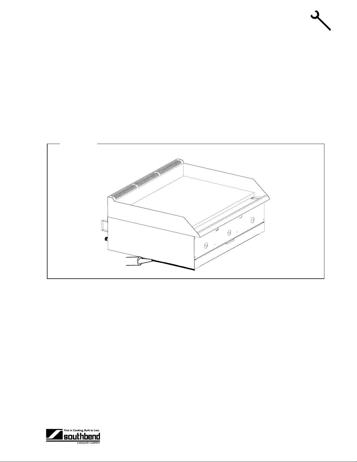
Step 2b: Installation Directly on a Non-Combustible Countertop Surface
The griddle may be installed directly onto a flat NON-COMBUSTIBLE surface, as follows:
1. Place the griddle in the posit ion that it will be used. Lift the griddle only from the ends, never f rom the
middle!
2. Connect the gas supply (see Step 4 on page 16), then return to this procedure.
3. Check that the griddle is in the position you want it to be in.
4. Seal the gridd le to the counterto p using G.E. or Dow Corn ing RT V, or the equi valent (as s hown i n Figur e
4 below). Consult local codes for exact requirements. A small bead of RTV around all four bottom
edges should be adequate. Open the front door to seal along the front edge of the frame.
5. Go on to Step 5 on page 17.
Figure 4
INSTALLATION
OPERATOR’S MANUAL 1182629 REV 2PAGE 9
Page 10
INSTALLATION COUNTER GRIDDLE
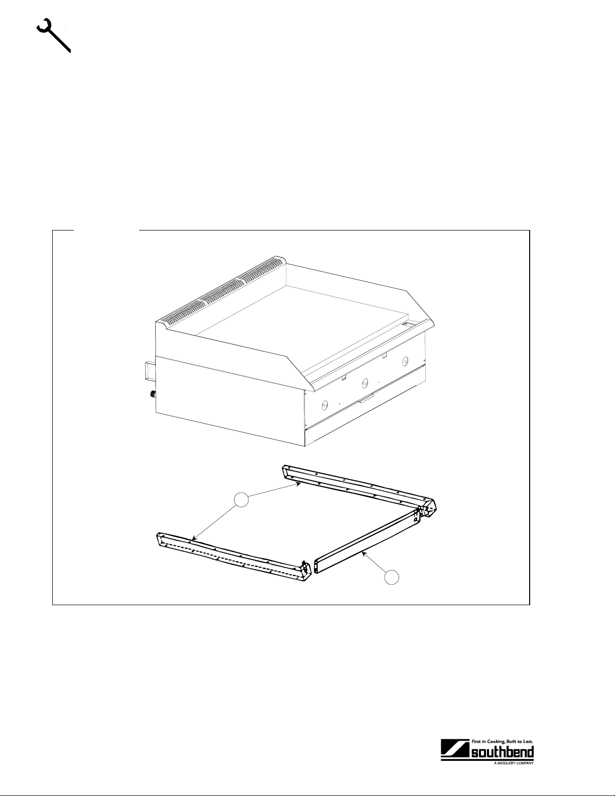
Step 2c: Installation on Insulated Base
The griddle may be installed ont o a flat NON-CO MBUSTIBLE ( but heat se nsitive) sur face using the optional
insulated base, as follows:
1. Attach the side pieces of the insu lated base (items “A” in Figur e 5 below) to the f ront piece (item “B”)
using the four sheet metal screws provided.
2. Posit ion the insula ted bas e on the surf ac e wher e you want the gridd l e to be locat ed.
3. Position the griddle on top of the insulated base. Lift the griddle only from the ends, never from the
middle!
4. Go on to Step 4 on page 16.
INSTALLATION
Figure 5
A
B
PAGE 10 OPERATOR’S MANUAL 1182629 REV 2
Page 11
COUNTER GRIDDLE INSTALLATION
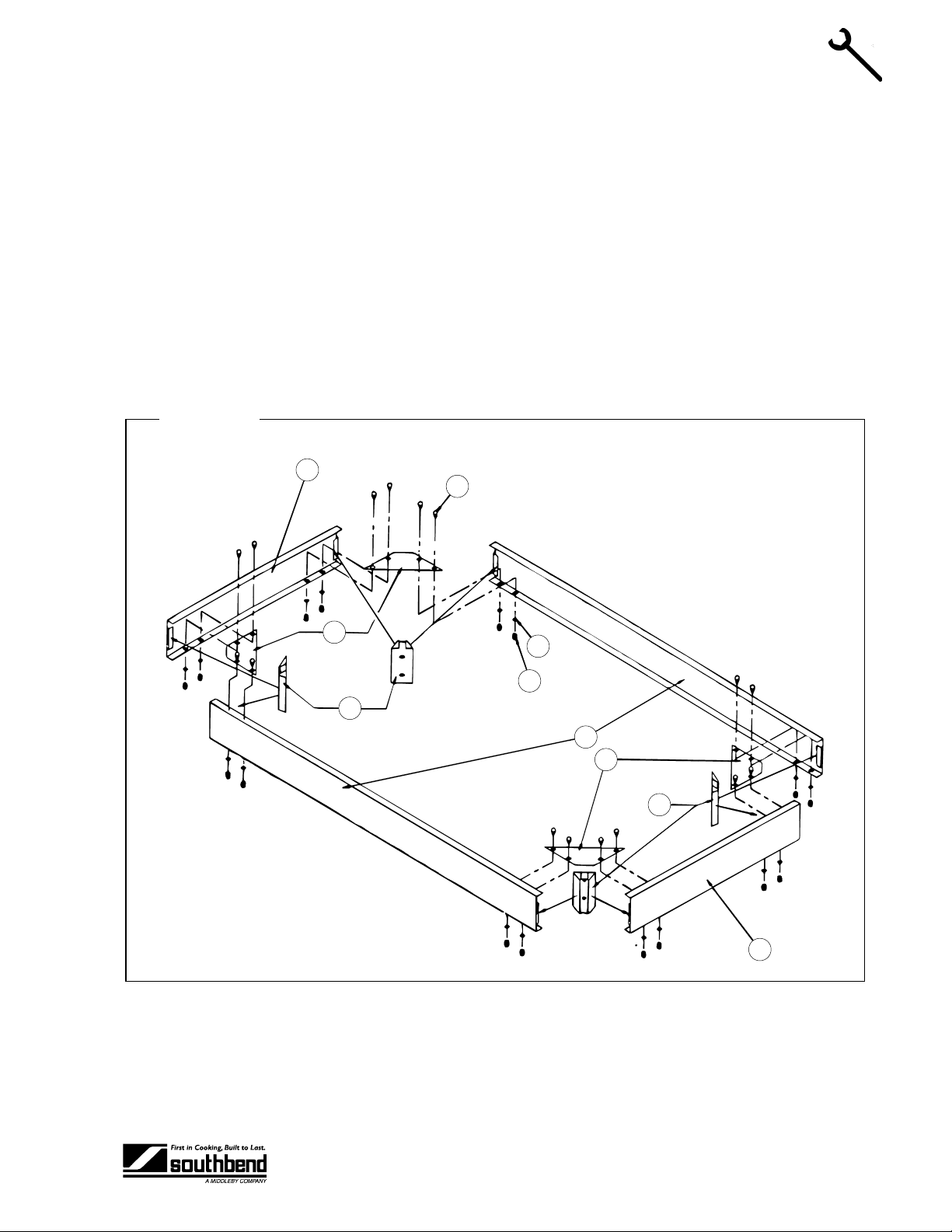
Step 2d: Installation on Floor Stand (24", 36", and 48" Models)
The 24", 36", and 4 8" griddles m ay be installe d on top of an opt ional flo or stand ( for 60" griddl es, go to Ste p
2e on page 13). The floor stand is shipped in a separate crate and must be assembled, as follows:
1. Position the bottom -brace pieces o n a flat surface, as shown in Figur e 6 below. Ther e are two bottomside braces (items “A”), a bottom-front brace (item “B”), and an identical bottom-rear brace (item “B”).
2. Position a corner brace (item “C”) in each corner, m atching the pre-punched h oles on the lower inside
flange of the bottom braces.
3. Position a leg brack et (item “D ”) into each c orner . Be s ure that the brac ket f langes are engaged into the
open hem of the bottom braces.
4. Use the sixteen 1/2"-l ong hex head bolts (it ems “E”), lock washers (items “F”), and acorn nuts ( items “G”)
to bolt the corner braces to the bottom braces. Only hand-tighten for now.
5. Check that the leg brackets are in the proper position, and that the outside corners are square.
Figure 6
A
E
INSTALLATION
C
D
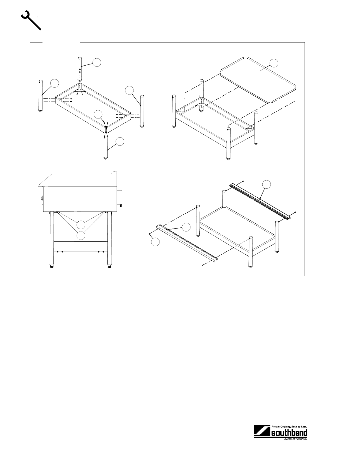
6. Use the eight 1-1/2" hex bolts (item s “H” in Figure 7) to attach t he two left-legs (item s “I”) and the two
right-legs (items “J”). “Left” and “ right” are as seen from the front or rear of the s tand. Be sure that the
small threaded-insert near the top of each leg faces either t he front or the rear of the stand, not a s ide.
Insert the bolts through the leg brackets and into the legs. Only hand-tighten the bolts for now.
F
G
B
C
D
A
OPERATOR’S MANUAL 1182629 REV 2PAGE 11
Page 12
INSTALLATION COUNTER GRIDDLE
Figure 7
INSTALLATION
J
I
I
H
J
N
O
M
L
K
L
7. Check the partially assembled stand to make sure that the legs are straight and that all corners are
square. Now tighten all bolts, but do not over tighten.
8. If legs with casters were ordered, lift the stand and sc rew the caster assemblies into the bottom of the
legs. The two casters with wh eel- lock s go on t he fr ont legs. Afte r the stand is ass embled, be sure to
connect the required restraint to protect the flexible gas connection (see Step 3 on page 15).
9. If the optional shelf was ordered (item “ K”), position it on top of the bottom braces. The down-flange
edge of the shelf should be on the front s ide of the stand. The s helf s im pl y rests o n th e bo ttom braces (it
is not bolted or screwed to the braces).
10. Position the front an d rear top supports (it ems “L”) over the legs. The pre-dril led holes should f ace the
outside of the stand to line up with the threaded- insert holes near the top of the legs. Use the four 5/8"
hex-head bolts (items “M”) to secure the top supports to the legs.
11. Attach the angle suppor t brackets (item “N”, shipped with the griddle) to the bott om of the of the gr iddle
using #10x1/2" sheet metal screws (item “O”, also shipped with the griddle).
12. Place the griddle on to p of the stand, m aking sure that the ang le brackets that you jus t installed on the
bottom of the griddle are inserted into the front an d rear top su pports. No add itional bolts or screws are
required. Lift the griddle only at the ends, never in the middle!
13. Go on to Step 4 on page 16.
PAGE 12 OPERATOR’S MANUAL 1182629 REV 2
Page 13

COUNTER GRIDDLE INSTALLATION
A
Step 2e: Installation on Floor Stand (60" Models)
A 60" griddle may be installed on top of an optional f loor stan d (for 24", 36 ", and 48" gr iddles, go to Ste p 2d
on page 11). The floor stand is shipped in a separate crate and must be assembled, as follows:
1. Position the bottom -brace piec es on a flat surface, as s hown in F igure 8 below. There are four bottomside braces (items “A”), and four front/rear bottom-braces (items “B”).
2. Position a corner brace (i tem “C”) in each inter ior corner, matchin g the pre-punched h oles on the lower
inside flange of the bottom braces.
3. Position the six leg brackets (item “D”); one in each cor ner of the stand, one front-center, and one rearcenter, as shown in F igure 8. Be sure that the brac ket flanges are engaged int o the open hem of the
bottom braces.
4. Use the thirty-two 1/2"-long hex head bolts (it ems “E”), lock washers (items “F”), and acor n nuts (items
“G”) to bolt the corner braces to the bottom braces. Only hand-tighten for now.
5. Check that the leg brackets are in the proper position, and that the outside corners are square.
Figure 8
INSTALLATION
A
C
D
F
G
B
C
E
B
C
D
A
A
C
D
C
E
B
C
D
B
6. Use the twelve 1-1/2" hex bolts (item s “H” in Figure 9) to attac h the two lef t-legs (item s “ I”), the two ri ghtlegs (items “J”) , and the two center- legs (item s “P”). “Lef t” and “right” are as seen from the front or rear
of the stand. Be sure that the sm all threaded-i nsert near the top of each leg f aces eith er the f ront or the
rear of the stand, not a side. Insert the bolts through the leg brackets and into the legs. On ly handtighten the bolts for now.
OPERATOR’S MANUAL 1182629 REV 2PAGE 13
Page 14

INSTALLATION COUNTER GRIDDLE
Figure 9
INSTALLATION
J
I
H
P
N
P
I
H
J
L
K
K
L
O
7. Check the partially assembled stand to make sure that the legs are straight and that all corners are
square. Now tighten all bolts, but do not over tighten.
8. If legs with casters were ordered, lift the stand and sc rew the caster assemblies into the bottom of the
legs. The two casters with wheel-locks go on the front corner legs. After the stand is assembled,
connect the required restraint to protect the flexible gas connection (see Step 3 on page 15).
9. If the optional shel ves were ordered ( items “K”), pos ition them on top of the bottom braces. The downflange edge of each shelf should be on the front side of the stand. The shelves simply rest on the bottom
braces (they are not bolted or screwed to the braces).
10. Position the front an d rear top supports (it ems “L”) over the legs. The pre-dril led holes should f ace the
outside of the stand to line up with the threaded- insert holes near the top of the legs. Use the s ix 5/8"
hex-head bolts (items “M”) to secure the top supports to the legs.
11. Attach the angle suppor t brackets (item “N”, shipped with the griddle) to the bott om of the of the gr iddle
using #10x1/2" sheet metal screws (item “O”, also shipped with the griddle).
12. Place the griddle on to p of the stand, m aking sure that the ang le brackets that you jus t installed on the
bottom of the griddle are inserted into the front an d rear top su pports. No add itional bolts or screws are
required. Lift the griddle only at the ends, never in the middle!
M
13. Go on to Step 4 on page 16.
PAGE 14 OPERATOR’S MANUAL 1182629 REV 2
Page 15

COUNTER GRIDDLE INSTALLATION
Step 3: Attach Restraint for Griddles Mounted on Casters
NOTICE
For an appliance equipped with casters, (1) the installation shall be made with a connector that
complies with the Standard for Connectors for Movable Gas Appliances , ANS I Z21.69 or Connectors
for Moveable Gas Applianc es, CAN/CGA-6.1 6, and a quick -disconnect devic e that com plies with the
Standard for Quick-Discon nect Devices for Use With Gas Fuel, ANSI Z21.4 1, or Quick Disconnect
Devices for Use with Gas Fuel, CAN1-6.9, (2) adequate means must be provided to limit the
movement of the appliance without d epending on the connect or and the quick-disc onnect device or
its associated piping to limit the appliance movement and (3) the restraining means should be
attached to a frame member on the back of the griddle.
Griddles mounted on a stand with casters or other movable surface must be equipped with a restraining
means to prevent accidental stress on the flexible gas connection.
1. Secur e t he r estr a in ing- d ev ice bracket (item “ B” in the following illus tr atio n) to a wall stud loc at ed as c lose
as possible to the appliance connector inl et a nd o utl et co nnec t ions. Use four #12 scr ews (i tems “C”) and
plastic anchors (items “A”) if necessary.
2. Install eye-bolt (item “F ”) to a fram e member on the re ar of the counter griddl e. Af ter check ing caref ully
behind the frame member for adequate clearance, drill a 1/4” hole through the frame member.
INSTALLATION
3. Thread hex nut (item “G”) and slide the washer (it em “H”) onto the e ye-bolt. Insert the e ye-bolt through
the 1/4” drilled hole and secure with a washer (item “H”) and nylon lock nut (item “I”).
4. Using the spring-loaded snap hooks, attach the restraining device to the bracket and the eye-bolt.
5. Using the cable clam p (item “D” ), adjust the restrainin g device extend ed length to pr event over -bending
or kinking of the appliance connector.
Figure 10
Note: For griddles not equipped with flame safety devices, be sure all valves are turned off prior to
disconnecting. After reconnecting, be sure all valves are turned off and all pilots are lit.
OPERATOR’S MANUAL 1182629 REV 2PAGE 15
Page 16

INSTALLATION COUNTER GRIDDLE
Step 4: Connect Gas Supply
The serial plate is located interior s ide of th e control p anel (see F igure 1 o n page 3). It i ndicates the type of
gas the griddle is equipp ed to burn. All Southb end equipm ent is adjusted at the factor y. Check t ype of gas
on serial plate. This appliance should be connected ONLY to the type of gas for which it is equipped.
If the griddle is being installed at over 2,000 feet altitude and that information was not specified when
ordered, contact the appropriate authorized Southbend Service Representative or the Southbend Service
Department. Failure to install with proper orifice sizing will result in poor performance and may void the
warranty.
These models are design-certified for operation on natural or propane gases. For natural gas, the
convertible regulator shipped with the griddle is set to deliver a 4” W.C. pressure to the manifold. For
INSTALLATION
propane gas, it is set to deliver 10” W.C.
An adequate gas supply is imperative. Undersized or low pressure lines will restrict the volume of gas
required for satisf ac tor y perf ormance. Fluctuations of more than 25% on natur al gas or 10% on propa ne gas
will create problems and affect burner operating characteristics. A 1/8” pressure tap is located on the
manifold to measure pressure.
Purge the supply line to clean out dust, dirt, or other foreign matter before connecting the line to the griddle.
Use pipe joint compound that is suitable for use with LP gas on all threaded connections.
! CAUTION
ALL PIPE JOINTS AND CONNECTIONS MUST BE TESTED THOROUGHLY FOR GAS LEAKS.
USE ONLY SOAPY W ATER FOR TEST ING ON ALL GASES. NE VER USE AN OPE N FLAME TO
CHECK FOR GAS LEAKS. ALL CONNECT IONS MUST BE CHECKED FOR L EAKS AFTER THE
GRIDDLE HAS BEEN PUT INTO OPERATION. TEST PRESSURE SHOULD NOT EXCEED 14”
W.C.
To connect the gas supply, do the following:
1. Check that the gas supply to the piping that will be connected to the griddle is shut off.
2. Check that the manual shut-off valve insid e the fr ont pan e l do or of the griddle is c los ed ( 6 0" models have
two shut-off valves).
3. Check that all control knobs on the griddle are turned “OFF.”
4. Attach the pressure regulator shi pped with the griddl e to the 3/4" NPT gas inlet co nnector loc ated on t he
rear of the griddle (s ee Figur e 11 belo w). Be sur e that the re gulat or is con nected so th at the gas flow is
in the same direction as the arrow on the bottom of the regulator.
5. Connect the vent line fr om the pressure regulat or to the outdoors in ac cordance with local c odes or, in
the absence of local codes, with the National Fuel Gas Code, ANSI Z223.1, Natural Gas Installation
Code, CAN/CGA-B149.1, or the Propane Installation Code, CAN/CGA-B149.2, as applicable.
6. Connect the gas inlet of the pressure re gulator to the bui lding’s suppl y system. No s egment of the gas
supply connection to the griddle should be smaller than 3/4" NPT. Standard pipe fittings are required.
7. Turn on gas supply.
8. Check for leaks using soapy water.
PAGE 16 OPERATOR’S MANUAL 1182629 REV 2
Page 17

COUNTER GRIDDLE INSTALLATION
Figure 11
Step 5: Final Positioning, Clearance Check, and Ventilation Check
1. Position the griddle where it will be operated.
INSTALLATION
2. Check that the griddle surface is level. The length of each leg is adjustable by screwing the bottom
portion of the leg in or out. The griddle must be level for proper operation!
3. Check for adequate clearances around the griddle (see page 5).
4. Check for adequate ventilation (see page 5).
Step 6: Check Pilot and Burner Operation
All griddles are adjusted at the f actory. However, p ilot heights, burner air shutters, and th ermostatic valves
should be checked at installation and adjusted if necessary. Do the following:
1. Turn main gas supply “ON”.
2. Check the manifold gas pressure using the procedure on page 22.
3. Foll o w the procedur e on pag e 20 to light the pilots .
4. Check (and, if necessary, adjust) the pilot flame heights using the procedure on page 23.
5. Follo w the procedure on pag e 19 to light the burn ers. Se t the c ontro l knobs to onl y lo w tem peratures for
now.
6. Check (and, if necessary, adjust) the burner air shutters using the procedure on page 23.
Step 7: Condition Griddle Surface
New griddles should be carefull y tempered and cared f or in order to a void possib le damage. To break in a
new griddle, do the following:
1. Wipe the griddle surface clean.
2. Light all the griddle burners and turn them to 200°F for one hour. Then gradually bring each griddle up to
frying temperature.
3. Spread thre e or four ounces of beef suet, or as a substitute, baking so da, to season it. N ever allow
water on a hot griddle and never wash it with soap and water.
OPERATOR’S MANUAL 1182629 REV 2PAGE 17
Page 18

INSTALLATION COUNTER GRIDDLE
Step 8: Check Griddle Temperature
Check (and, if necessary, adjust) the thermostatic valves that control the griddle’s surface temperature.
Follow the procedure on page 24.
INSTALLATION
PAGE 18 OPERATOR’S MANUAL 1182629 REV 2
Page 19

COUNTER GRIDDLE OPERATION
OPERATION
! DANGER
EXPLOSION HAZARD
Purchaser of equipment m ust post in a prom inent location, detailed instruct ions to be follo wed in the
event the operator smells gas. Obtain the instructions from the local gas supplier.
! CAUTION
To eliminate gas build up which could result in an explosion, in the event of main burner ignition
failure a five minute purge period must be observed prior to re-establishing ignition source.
! CAUTION
Pilots, when out, do not interrupt the flow of gas to the burners. Co nsequentl y, it is the respo nsibilit y
of the operator to chec k the ignition of the burn ers, immediate ly after burner value has bee n turned
“ON”. Should ignition fail after 10 seconds, turn off burners, wait 5 minutes, and then try again.
! WARNING
UNDER NO CIRCUMSTANCES IS THE GRIDDLE TO BE USED FOR HEATING STOCK POTS.
SUCH USE AUTOMATICALLY VOIDS THE WARRANTY.
NEVER COOL THE GRIDDLE BY APPLYING ICE OR WATER TO THE GRIDDLE SURFACE.
DAMAGE DUE TO MISUSE IS NOT COVERED BY THE WARRANTY.
DO NOT STRIKE THE GRIDDLE SURFACE W ITH THE EDGE OF COOKING IMPLEMENT S TO
CLEAN THE IMPLEMENTS. SUCH ACTION WILL CUT AND PIT T HE GRIDDLE PLAT E, LEAV ING
IT ROUGH AND HARD TO CLEAN.
ALWAYS HEAT THE GRIDDLE SLOWLY. DO NOT HEAT THE GRIDDLE ABOVE 550°F.
OPERATION
GRIDDLE OPERATION
Each 12"-wide gri ddle section has a thermostatic -control knob on the front panel that directly controls the
flow of gas, and so the heat. Turn the knob clockwise to increase the heat; turn it counterclockwise to
reduce the heat.
The griddle will take approximately 13 minutes to heat to 350°F.
Do not waste gas or abuse equipm ent by leaving control knobs set at a h igh temperature if not required.
During idle periods, set control knobs to low temperature settings to keep griddle warm.
After each period of us e, allow the griddle sur face to cool normally. At t he end of each day’s use, t urn all
control knobs to the “OFF” pos ition. After th e griddle has cooled, coat t he griddle sur face with a light film of
cooking oil to protect the surface from moisture.
OPERATOR’S MANUAL 1182629 REV 2PAGE 19
Page 20

OPERATION COUNTER GRIDDLE
f
LIGHTING THE PILOTS
If one or more of the burners does not ignite, check that the pilot( s) are lit. The controls for the pilots are
located on the front of the gr id dl e, b ehi nd t he lo wer front panel door (s ee Fi gur e 12 on p age 20). To l igh t th e
pilot(s), do the following:
1. Turn all griddle-thermostat controls to the “OFF” position.
2. Open the grease/control door at the bottom of the front of the griddle.
3. Turn the main shut-off valve to the “ON” position (if it is not already ON).
4. For each pilot, press and hold the re d pilot button an d light the pilot (e ither with a m atch, or, o n models
with electronic ignition, b y pressing the electron ic ignition butto n to generate a sp ark). Continue to hold
the pilot button for 45 s econds, or unt il the pilot rem ains lit. Note tha t 24" models ha ve one pilot, 36" &
48" models have t wo pilots, and 60" models ha ve three pilots (one pilot a nd one shut-off val ve in one
burner compartment, and two pilots and one shut-off valve in a sec ond burner com partm ent). Note that
the left pilot must be lit before the right pilot can be lit.
5. If a pilot is extinguished or the gas supply is interrupted, wait five minutes and repeat the above steps.
6. Turn all griddle thermostat controls to the “ON” position to check that the pilots will ignite the burners.
OPERATION
Figure 12
This drawing shows a Model SGS-36 with the front panels removed so you can see the interior parts.
Main Shut-Of
Valve
Note: 24" models have one pilot, 36" & 48" models have two pilots, and 60" models have three pilots (and two shut-off valves).
Left Pilot
Button
Right Pilot Button
(36" & 48" Models)
Spark Switch Button
(Electronic Models)
Grease Drawer
OVERNIGHT SHUTDOWN
To shut down the griddle for overnight, turn all the burner control knobs to the “OFF” position to turn the
burners off. The pilots will remain lit.
EXTENDED-PERIOD SHUTDOWN
To shut down the griddle for an extended perio d (or bef ore discon necting t he gas sup ply), turn all the b urner
control gas knobs “OFF,” then turn the main gas supply valve(s) to “OFF” (see Figure 12 above).
PAGE 20 OPERATOR’S MANUAL 1182629 REV 2
Page 21

COUNTER GRIDDLE CLEANING
CLEANING
Southbend equipment is constructed with the best quality materials and is designed to provide durable
service when properl y maintained. To ex pect the best perf ormance, your equipment m ust be maintained in
good condition and cleaned dail y. Naturally, the frequency and extent of c leaning depends on the am ount
and degree of usage.
Daily:
A. Remove, empty, and clean grease drawers.
B. Clean griddle drain chutes.
Monthly:
A. Clean around burner air mixers and orifices if lint has accumulated.
B. Visually assure proper pilot operation.
CARE OF GRIDDLE SURFACE
Never allow water on a hot griddle and never wash it with soap and water.
Use a Norton Alundum Griddle Bric k to clean the griddle. Always rem ember to heat gr iddle slowly beca use
quick heat may cause costly damage. Griddle plates cannot be guaranteed against damage due to
carelessness. Never place utensils on griddle. Do not overheat griddle above 550°F, as this will cause
warpage or breakage.
Do not use any type of steel wool. Small particles m a y be left o n the s urfac e and get into f ood pr oduc ts. Do
not clean spatula b y hitting the e dge on the grid dle plate. Such action will only c ut and pit t he griddle plate,
leaving it rough and hard to clean.
CARE OF STAINLESS STEEL SURFACES
To remove normal dirt, grease and prod uct residue from stainless s teel that operates at LOW temperature,
use ordinary soap and water (with or without detergent) applied with a sponge or cloth. Dry thoroughly with a
clean cloth.
To remove grease and food splatter, or condensed vapors, that have BAKED on the equipment, apply
cleanser to a damp cloth or sponge and ru b cleanser on the m etal in the direction of the polishing lines on
the metal. Rubbing cle anser, as gently as possible, in the dir ection of the polished lines will not m ar the
finish of the stainless steel. NEVER RUB WITH A CIRCULAR MOTION. Soil an d burnt deposits which do
not respond to the above procedure can us ually be removed by rubbing the s urface with SCOTCH-BRITE
scouring pads or STAINLESS sc ouri ng pads . DO NOT USE ORDINAR Y ST EEL WOOL, as any partic l es lef t
on the surface will rus t and f ur th er spoi l t he a ppearance of the fin is h. N EV ER US E A WIRE BRU SH, STEEL
SCOURING PADS (EXCEPT STAIN LESS), SCRAPER, FIL E OR OTHER STEEL TO OLS. Surfaces whic h
are marred collect dirt more rapidly and become more difficult to clean. Marring also increases the possibility
of corrosive attack. Refinishing may then be required.
CLEANING
“Heat tint” is a darkened area that can appear on a stainless steel surface where the area has been
subjected to excessive heat. These darkened areas are caused by thickening of the protective surface of the
stainless steel and are not h armful. He at tint ca n norm ally be rem oved b y the foregoi ng, but tint which does
not respond to this procedure calls for a vigorous scouring in the direction of the polish lines, using
SCOTCH-BRITE scouring pads or a STAINLESS scouring pad in combination with a powered cleanser.
Heat tint action may be lessened by not applying, or by reducing heat to equipment during slack periods.
OPERATOR’S MANUAL 1182629 REV 2PAGE 21
Page 22

ADJUSTMENTS COUNTER GRIDDLE
ADJUSTMENTS
! WARNING
ADJUSTMENTS AND SERVICE WORK MAY BE PERFORMED ONLY BY A QUALIFIED
TECHNICIAN WHO IS EXP ERIENCED IN, AND KNOW LEDGEABLE WITH, THE O PERATION OF
COMMERCIAL COOKING EQUIPMENT. HOWEVER, TO ASSURE YOUR CONFIDENCE,
CONTACT YOUR AUTHORIZED SERVICE AGENCY FOR RELIABLE SERVICE, DEPENDABLE
ADVICE OR OTHER ASSISTANCE, AND FOR GENUINE FACTORY PARTS.
NOTICE
The warranty will be void and the manuf ac turer relie ved of all respo ns ib il ity if…
(A) Service work is performed by other than a qualified technician, or
(B) Other than genuine Southbend replacement parts are installed.
Before making any adjustment, make sure the griddle is connected to the type of gas for which it is
equipped. That inf ormation is on the serial plate, which is located on the inside of the control panel (see
Figure 1 on page 3).
ADJUSTMENTS
MANIFOLD GAS PRESSURE CHECK
The pressure regulator is connected to the griddle’s gas connection, outside the rear left corner of the
griddle. The pressure regulator is fac tory se t at 4” W.C. for natural gas a nd 10" W .C. for propane. T o c heck
the manifold pressure, do the following:
1. Turn all burner valves to “OFF” position.
2. Turn main gas valve to entire griddle off.
3. Remove front panel and locate 1/8” plug in manifold. (Note that a 60" model has two burner
compartments, and so has two manifolds.)
4. Remove plug and install a fitting appropriate to connect a manometer.
5. Turn on main gas to griddle and light pilots (the procedure is described on page 20).
6. Turn all burners to full “ON” position and read manometer.
7. If manometer does not r ead 4” W.C. for natural gas (or 10” W .C. for propane gas ), check the incoming
gas line for proper pressure.
8. Remove manometer fitting and replace plug in manifold.
9. Replace front panel.
10. Turn on main gas to griddle and light pilots.
PAGE 22 OPERATOR’S MANUAL 1182629 REV 2
Page 23

COUNTER GRIDDLE ADJUSTMENTS
PILOT FLAME ADJUSTMENT
The pilots are adjus ted at the factory. If later the pi lots are over-adjusted to the point where the f lame is
leaving its port, or “blowing off,” the result is an unstable condition in which the pilot may extinguish. If
necessary, adjust each burner’s pilot using the following procedure:
1. Open the door on the l ower front of the griddle, rem ove the thermostat knobs, and remove the control
panel by removing the screws holding it in place.
2. If necessary, light the pilot (the procedure is described on page 20).
3. Locate the pilot adjus tment valve (s ee Figure 13 belo w). Turn the pil ot adjustment s crew to the right to
increase the size of the pilot flame, or to the left to dec reas e t he s i ze of the pi lot f lame. The flam e should
be about 1/2" high and cover the thermocouple tip.
4. Repeat Step 3 for each pilot (24" models have one pilot, 36" & 48" models have two pilots, and 60"
models have three pilots).
5. Replace the control panel and knobs.
Figure 13
Pilot Flame Adjustment Screw
ADJUSTMENTS
BURNER FLAME ADJUSTMENT
The burners are adjusted at the factor y. If necessary to adjust the bur ner flames, do the f ollowing for each
burner:
1. Turn the burner’s control knob to the full ON position.
2. If the griddle was cold, wait 5 minutes before adjusting the burner flame.
3. Loosen the set screw that holds the sheet-metal air shutter in place.
4. If the burner flam e is blowing or lifting off the burner ports, close the air shutter until a s table flame is
obtained. If instead the flame is yellow-tipping, open the air shutter until a stable flame is obtained.
5. Tighten the set screw that holds the sheet-metal air shutter in place.
6. Repeat Steps 1 through 5 for each burner (24" models have two burners, 36" models have three
burners, 48" models have four burners, and 60" models have five burners).
OPERATOR’S MANUAL 1182629 REV 2PAGE 23
Page 24

ADJUSTMENTS COUNTER GRIDDLE
THERMOSTAT ADJUSTMENT
Each burner’s control k nob operates a s nap-act ion therm os tatic v alve that was a djusted a t the f actor y. If th e
griddle surface tem perature is differ ent from the therm ostat dial setting, adjus t the valve usin g the follo wing
procedure:
1. Turn all the control knobs to the 300°F.
2. Wait 30 minutes (or 1 hour if the griddle was cold).
3. Place a reliable th erm ometer or test- instrum ent thermocouple (abl e to regis ter 300 °F) half way back from
the front to the back of the griddle and d irectly over a bur ner (in line with the burner’s co ntrol knob, see
Figure 14 below). Check the tem peratur e o ver eac h burner ev er y fi ve minutes until the t emperature over
each burner stabilizes and does not change by more than 30°F between two consecutive
measurements.
4. If the temperature over any burner is not within 30°F of the knob setting (300°F), adjust the
corresponding therm ostatic valve. To do so , remove the k nobs and control p anel, adjust th e calibration
screw on the therm ostatic va lve (s ee F igure 1 4 belo w), rep lace t he knobs an d c ontro l panel, the n rep eat
Step 3.
Figure 14
ADJUSTMENTS
Measure each temperature
halfway back from front to
back and directly over the
corresponding burner (in line
with the control knob).
Calibrate the valve using the Thermostat Calibration
Screw located at the base of the stem. Turn the
screw clockwise to increase the temperature, or
counterclockwise to decrease the temperat ure.
PAGE 24 OPERATOR’S MANUAL 1182629 REV 2
Page 25

COUNTER GRIDDLE ADJUSTMENTS
CONVERSION FROM ONE TYPE OF GAS TO ANOTHER
Each griddle is shipped equippe d for use with either natural g as or LP gas (propa ne). To convert a gr iddle
from one type of gas to another, do the following:
1. Remove the front panel by removing the knobs and screws on the front.
2. For each burner, replace the orifice with the type appropriate for the type of gas t hat will be used (see
parts list on page 3 0). For special gas m ixtures, and for altitudes above 2,000 feet, consult factor y for
appropriate orifice sizes.
3. For each pilot, replace the pilot assembly (item 20 in the parts list on page 30; 24" models have one pilot,
36" & 48" models have two pilots, and 60" models have three pilots).
4. Re-install the front panel.
5. Remove the hex-threaded plug from the pressure regulator (on the rear of the griddle). Inside is a
removable insert. Pull the inser t out, turn it around, and put it back in so that the end f acing you h as the
letters corresponding to the t ype of gas that will be used (“NAT” or “ LP”). Re-attach the hex-threaded
plug.
6. Check the manifold pressure (the procedure is on page 22).
ADJUSTMENTS
OPERATOR’S MANUAL 1182629 REV 2PAGE 25
Page 26

TROUBLESHOOTING COUNTER GRIDDLE
TROUBLESHOOTING
Problem Look for -
Griddle will not heat up – Main gas supply to griddle is “OFF”
– Pilot(s) not lit
– Defective thermostat(s)
– Clogged orifice or burner ports
Burners produce excessive carbon deposits – Incorrect gas type or orifice size
– Incorrect supply pressure
– Incorrect burner air mixer adjustment
– Burner orifice out of alignment with burner
– Incorrect orifices
Pilot produces excessive carbon deposits – Pilot gas not adjusted properly
– Incorrect pilot orifice
Pilot will not stay lit
Electronic ignition module (on models so equipped) will not
generate a spark
– Pilot not adjusted properly
– Clogged or dirty orifice
– Draft condition
– Improper ventilation system
– Air in gas line
– Valve end of thermocouple corroded or loose
– Pilot shield needs to be moved closer to pilot
– Improper gas pressure
– Incorrect gas supply size (not enough volume)
– Defective thermocouple
– Dead battery in ignition module
– Defective spark module
PAGE 26 OPERATOR’S MANUAL 1182629 REV 2
Page 27

COUNTER GRIDDLE PARTS
PARTS
NOTICE
INSTALLATION OF OTHER THAN GENUINE SOUTHBEND PARTS WILL VOID T HE WARRANTY
ON THIS EQUIPMENT.
The serial plate is located inside of the control panel on the front of the griddle (see Figure 1 on page 3).
Replacement parts may be ordered either thr ough a Southbend Auth orized Parts Dis tributor or a S outhbend
Authorized Service Agency.
When ordering parts, please supply the Model Number, Serial Number, Part Number, and Description.
For parts not listed, consult a Southbend Authorized Parts Distributor or Southbend Authorized Service
Agency. Consult the Southbend Au thorized Par ts/Servic e Distributor list for the Authorized P arts suppli er in
your area. If this list is not available, call Southbend at 1-800-348-2558 to obtain this list.
Except where the a part number is expl icitly associated with a p articular model num ber, all parts listed are
used by all the models covered b y this manual: SG S-24, SGS-24 E, SGS-36, SG S-36E, SGS- 48, SGS-48E,
SGS-60, and SGS-60E. (An “E” suffix on a model number indicates that the model is equipped with
electronic ignition for lighting the pilots.)
Index of Parts Diagrams
Page Number Description
2 8 Chassis Parts
30 Gas System Parts
32 Floor Stand Parts for 24", 36", and 48" Width Griddles
34 Floor Stand Parts for 60" Width Griddles
36 Countertop Legs and Insulated-Base Parts
OPERATOR’S MANUAL 1182629 REV 2PAGE 27
PARTS
Page 28

PARTS COUNTER GRIDDLE
Chassis Parts
See drawing on following page.
Key Part Number
1 1180299 2222Bracket, standoff
2 1182583 2345Bulb cover weld assembly
3 1182586 2345Knob
4 1182588 1111Drawer guide
5 1182591 1112Hinge, male, right
6 1182592 1112Hinge, male, left
7 1182604 1111Grease drawer weld assembly
8 1182637 1112Catch, magnetic
9 1182554 1233Burner divider
10 1182557 2345Pilot assembly bracket
11 1182558 2224Hinge bracket
12 1182611 1 - - - Smooth-griddle weld as sembly, 24" **
1182608 - 1 - - Smooth-griddle weld assembly, 36" **
1182609 - - 1 - Smooth-griddle weld assembly, 48" **
1182605 - - - 1 Smooth-griddle weld assembly, 60" **
13 1182612 1 - - 1 Door weld assembly, 24"
1182620 - 1 - 1 Door weld asse mbly, 36"
1182624 - - 1 - Door weld assembly, 48"
14 1182618 1 - - 1 Control panel, 24"
1182552 - 1 - 1 Control panel, 36"
1182627 - - 1 - Control panel, 48"
*** 1180145 1 - - 1 Polypanel, 24"
1182631 - 1 - 1 Polypanel, 36"
1182632 - - 1 - Polypanel, 48"
* Griddle width is 24" for models SGS-24/24E, 36" for models SGS-36/36E, 48" for models SGS-48/48E, and 60" for models SGS-60/60E.
** Contact Southbend to obtain part numbers for optional grooved-griddle assemblies.
*** Not shown on drawing.
Quantity for Griddle Width*
24" 36" 48" 60"
Description
PARTS
PAGE 28 OPERATOR’S MANUAL 1182629 REV 2
Page 29

COUNTER GRIDDLE PARTS
Chassis Parts
See parts list on previous page. Model SGS-24 is shown.
12
2
14
1
9
3
11
10
4
13
5
8
7
OPERATOR’S MANUAL 1182629 REV 2PAGE 29
6
PARTS
Page 30

PARTS COUNTER GRIDDLE
Gas System Parts
See drawing on following page.
Key Part Number
1 1146806 1112Nipple, pipe, close, black, 1/2"
2 1160008 1112Elbow, brass
3 1164085 1223Valve assembly, pilot
4 1166150 2345Male elbow
5 1181499 2345Tubing, 3/8 x 1.750
6 1182553 2345Valve assembly, thermostat
7 1182562 1112Elbow bracket weld assembly
8 1182564 1112Supply pipe bracket weld assembly
9 1182566 1112Tube, 5/8" supply
10 1182610 2345Burner assembly
11 1182639 1112Pilot tube left
12 1182640 1223Pilot tube extension
13 1-5771 1112Valve, shut off, 1/2"
14 P9158 2224Connector, brass, 68C-10-8
15 P5244-4 1112Pipe reducer
16 1182574 1 - - 1 24" manifold weld assembly
1182560 - 1 - 1 36" manifold weld a ssembly
1182571 - - 1 - 48" manifold weld assembly
17 1182594 1 - - 1 Safety valve, single
1182567 - 1 1 1 Safety valve, dual
18 1182633 1 - - 1 Tube, loop to safety, single
1182638 - 1 1 1 Tube, loop to safety, dual
19 1182641 - 1 - 1 Tube, pilot 36" right
1182642 - - 1 - Tube, pilot 48" right
20 1182628 1223Pilot assembly (NAT gas)
1182635 1223Pilot assembly (LP gas)
21 1182709 1223Electrode **
22 1182707 1111Cover, electronic ignition **
23 1182705 1111Battery, 9V **
24 1182706 1111Module, spark **
25 1182704 1111Switch, ignition **
*** 1057200 2345Orifice fitting
*** 1008732 2345Orifice NAT gas
*** 1008752 2345Orifice LP gas
*** 1178815 1111Pressure regulator, LP/NAT
*** 1182648 - - - 1 Tube, rear, gas supply, 60" only
* Griddle width is 24" for models SGS-24/24E, 36" for models SGS-36/36E, 48" for models SGS-48/48E, and 60" for models SGS-60/60E.
** Only for models with electronic ignition (models SGS-24E, SGS-36E, SGS-48E, and SGS60E)
*** Not shown on drawing.
Quantity for Griddle Width*
24" 36" 48" 60"
Description
PARTS
PAGE 30 OPERATOR’S MANUAL 1182629 REV 2
Page 31

COUNTER GRIDDLE PARTS
Gas System Parts
See parts list on previous page. Model SGS-36 is shown.
14
10
7
8
20
6
15
14
9
2
13
11
1
3
17
12
18
19
4
5
16
Additional Parts for Models
with Electronic Ignition
21
22
25
23
24
OPERATOR’S MANUAL 1182629 REV 2PAGE 31
PARTS
Page 32

PARTS COUNTER GRIDDLE
Floor Stand Parts for 24", 36", and 48" Width Griddles
See drawing on following page.
Key
1 1173709 1173709 1173709 2 Bottom brace, left & right sides
2 1173710 1173723 1173724 2 Bottom brace, front & rear
3 1173707 1173707 1173707 4 Leg bracket
4 1173706 1173706 1173706 4 Corner brace
5 1146500 1146500 1146500 16 1/4" lock washer
6 1146200 1146200 1146200 16 1/4" - 20 x 1/2 hex head bolt
7 1164827 1164827 1164827 16 1/4 - 20 acorn nut
8 1146203 1146203 1146203 8 1/4 - 20 x 1-1/4 hex head bolt
9 1173721 1173720 1173722 2 Front & rear top support
10 1146518 1146518 1146518 4 1/4 - 20 x 5/8 hex head bolt
11 1173590 1173590 1173590 2 Left leg assembly
12 1173589 1173589 1173589 2 Right leg assembly
13 1173717 1173718 1173719 1 Shelf (optional)
14 1173725 1173726 1173727 2 Mount angle
15 1146304 1146304 1146304 4 #10 x 1/2 sheet metal screw
** 1174264 1174264 1174264 2 Caster with lock (for front legs)
** 1174263 1174263 1174263 2 Caster without lock (for rear legs)
** 1174265 1174265 1174265 1 Caster package (two casters with lock, two casters without lock)
* Griddle width is 24" for models SGS-24/24E, 36" for models SGS-36/36E, and 48" for models SGS-48/48E.
** Not shown on drawing.
Part Number for Griddle Width*
24" 36" 48"
1173592 1173592 1173592 2 Left leg as sembly for use with cas ters
1173591 1173591 1173591 2 Right leg assembly for u se wit h c asters
Qty Description
PARTS
PAGE 32 OPERATOR’S MANUAL 1182629 REV 2
Page 33

COUNTER GRIDDLE PARTS
Floor Stand Parts for 24", 36", and 48" Width Griddles
See parts list on previous page. Model SGS-36 is shown.
1
6
11
12
4
3
11
8
12
5
7
2
4
3
1
13
14
15
9
9
10
PARTS
OPERATOR’S MANUAL 1182629 REV 2PAGE 33
Page 34

PARTS COUNTER GRIDDLE
Floor Stand Parts for 60" Width Griddles
See drawing on following page.
Key Part Number Qty Description
1 1173709 4 Bottom brace, left & right sides
2 1173728 4 Bottom brace, front & rear
3 1173707 8 Leg bracket
4 1173706 8 Corner brace
5 1146500 32 1/4" lock washer
6 1146200 32 1/4" - 20 x 1/2 hex head bolt
7 1164827 32 1/4 - 20 acorn nut
8 1146203 16 1/4 - 20 x 1-1/4 hex head bolt
9 1173879 2 Front & rear top support
10 1146518 6 1/4 - 20 x 5/8 hex head bolt
11 1173590 2 Left leg as sembly
1173592 2 Left leg assembly for use with casters
12 1173589 2 Right leg assembly
1173591 2 Right leg assembly for use with casters
13 1173731 2 Cen ter leg assembly
1173732 2 Center leg assembly for use with casters
14 1173881 2 Shelf (optional)
15 1173733 2 Mount angle
16 1146304 6 #10 x 1/2 sheet metal screw
* 1174264 2 Caster with lock (for front corner legs)
* 1174263 4 Caster without lock (for front-center land rear legs)
* 1173708 1 Caster package (two casters with lock, four casters without lock)
* Not shown on drawing.
PARTS
PAGE 34 OPERATOR’S MANUAL 1182629 REV 2
Page 35

COUNTER GRIDDLE PARTS
Floor Stand Parts for 60" Width Griddles
See parts list on previous page. Model SGS-60 is shown.
1
4
3
5
7
2
12
11
13
4
6
2
4
3
1
1
2
4
3
4
6
2
4
3
1
8
13
15
16
11
14
14
12
9
9
10
PARTS
OPERATOR’S MANUAL 1182629 REV 2PAGE 35
Page 36

PARTS COUNTER GRIDDLE
Countertop Legs and Insulated-Base Parts
3
1
2
Key
** 1146304 1146304 1146304 1146304 4 Screw #10 x 1/2 truss head
** 1173888 1173889 1173890 1173891 1 Insulator base assembly (1 front, 2 sides, and 4 screws)
24" 36" 48" 60"
1 1163561 1163561 1163561 1163561 4 4" leg (single)
1172857 1172857 1172857 1172857 1 4" leg (set of 4)
2 1173884 1173885 1173886 1173887 1 Insulator fro nt piec e
3 1173883 1173883 1173883 1173883 2 Insulator side piec e
* Griddle width is 24" for models SGS-24/24E, 36" for models SGS-36/36E, 48" for models SGS-48/48E, and 60" for models SGS-60/60E.
** Not shown on drawing.
Part Number for Griddle Width*
Qty Description
PARTS
PAGE 36 OPERATOR’S MANUAL 1182629 REV 2
Page 37

COUNTER GRIDDLE
OPERATOR’S MANUAL 1182629 REV 2PAGE 37
Page 38

COUNTER GRIDDLE
COUNTER GRIDDLE
A product with the So uthbend nam e incorporates the best in durabilit y and low mainten ance. W e
all recognize, however, that replacement parts and occasional professional service may be
necessary to extend the useful life of this unit. When service is needed, contact a Southbend
Authorized Service Agency, or your dealer. To avoid confusion, always refer to the model number,
serial number, and type of your unit.
Southbend
1100 Old Honeycutt Road, Fuquay-Varina, NC 27526
(800) 348-2558 or (919) 552-9161 • FAX (800) 348-2558 or (919) 552-9798
PAGE 38 OPERATOR’S MANUAL 1182629 REV 2
 Loading...