

Page 1
$6.00
southbend
A MIDDLEBY COMPANY
OWNER'S MANUAL
INSTALLATION
USER'S GUIDE
SERVICE
PARTS
IMPORTANT
FOR FUTURE REFERENCE
Please complete this
information and retain this
manual for the life of the
equipment.
MODEL #__________________
SERIAL #__________________
DATE PURCHASED__________
GAS CHAR BROILERS
MODELS: SCB-24 SCBC-24
SCB-36 SCBC-36
SCB-48 SCBC-48
SCBC60
(Includes all models with suffixes, R, A, AR)
These instructions should be read thoroughly before attempting installation. Installation and
Start Up should be performed by a qualified service technician. The Manufacturer,
Southbend (Head Office: 1100 Old Honeycutt Rd., Fuquay-Varina, North Carolina 27526),
informs you that unless the installation instructions for the above described Southbend
product are followed and performed by a qualified service technician, (a person experienced
in and knowledgeable concerning the installation of commercial gas and/or electrical cooking
equipment) then the terms and conditions of the Manufacturer's Limited Warranty will be
rendered void and no warranty of any kind shall apply.
If the equipment has been changed, altered, modified or repaired by other than a qualified
service technician during or after the 12-month limited warranty period, then the
manufacturer shall not be liable for any incidental or consequential damages to any person
or to any property which may result from the use of the equipment thereafter. Some States
do not allow the exclusion or limitation of incidental or consequential damages, so the above
limitation or exclusion thereto may not apply to you.
In the event you have any questions concerning the installation, use, care, or service of the
product, write Customer Service Department, Southbend, 1100 Old Honeycutt Rd., Fuquay Varina, North Carolina 27526.
WARNING: Improper installation, adjustment, alteration, service or maintenance can cause
property damage, injury or death. Read the installation, operating and maintenance instructions
thoroughly before installing or servicing this equipment.
CHAR BROILERS
(Manual Section BR)
Page 2
Congratulations! You have just purchased one of the finest pieces of heavy-duty, commercial cooking equipment on the market
A MIDDLEBY COMPANY
1100 Old Honeycutt Road
today.
You will find that your new equipment, like all Southbend equipment, has been designed and manufactured to some of the
toughest standards in the industry — those of Southbend. Each piece of Southbend equipment has been carefully engineered and
designs have been verified through laboratory tests and field installations in some of the more strenuous commercial cooking
applications. With proper care and field maintenance, you will experience years of reliable, trouble -free operation from your
Southbend equipment. To get the best results, it's important that you read this manual carefully.
TABLE OF CONTENTS:
SECTION ONE - INSTALLATION
Specifications ......................................…………...... 1
Installation .....................................……………........ 2
SECTION TWO - USER'S GUIDE
Warranty.........................................…………….......
Operation....................................……………............
Maintenance............................…………........... . ....
SECTION THREE - SERVICE
Adjustments ..................................……............ .... .. 1
Troubleshooting .............................…....................... 2
SECTION FOUR - PARTS
Parts List.......................................……..................... 1
1
2
4
CAUTION: POST IN PROMINENT LOCATION INSTRUCTIONS TO BE FOLLOWED IN THE
EVENT THE SMELL OF GAS IS DETECTED. THIS INFORMATION SHALL BE OBTAINED
FROM LOCAL GAS SUPPLIER.
RETAIN THIS MANUAL FOR FUTURE REFERENCE.
INTENDED FOR COMMERCIAL USE ONLY. NOT FOR HOUSEHOLD USE.
FOR YOUR SAFETY
DO NOT STORE OR USE GASOLINE OR OTHER FLAMMABLE VAPORS
AND LIQUIDS IN THE VICINITY OF THIS OR ANY OTHER APPLIANCE.
KEEP AREA AROUND APPLIANCES FREE AND CLEAR FROM COMBUSTIBLES.
IN THE EVENT A GAS ODOR IS DETECTED. SHUT DOWN EQUIPMENT AT THE MAIN
SHUTOFF VALVE AND CONTACT THE LOCAL GAS COMPANY OR GAS SUPPLIER FOR
SERVICE.
southbend
Fuquay, NC 27526
(919) 552-9161
FAX (919) 552-9798
(800) 348-2558
Page 3
GAS CHAR BROILER
USER'S GUIDE
LIMITED WARRANTY
Southbend warrants that the equipment, as supplied by the factory to the original purchasers, is free from defects in materials
and workmanship. Should any part thereof become defective as a result of normal use within the period and limits defined
below, then at the option of Southbend such parts will be repaired or replaced by Southbend or its Authorized Service Agency.
This warranty is subject to the following conditions:
If upon inspection by Southbend or its Authorized Service Agency it is determined that this equipment has not been used in an
appropriate manner, has been modified, has not been properly maintained, or has been subject to misuse or misapplication,
neglect, abuse, accident, damage during transit or delivery, fire, "flood, riot or Act of God, then this warranty shall be void.
Specifically excluded under this warranty are claims relating to installation; examples are improper utility connections and
improper utilities supply. Claims relating to normal care and maintenance are also excluded; examples are calibration of
controls, and adjustments to pilots and burners.
Equipment failure caused by inadequate water quality is not covered under warranty. WATER QUALITY must not exceed the
following limits: Total Dissolved Solids (TDS) - 60 PPM (Parts Per Million). Hardness - 2 Grains or 35 PPM, PH Factor
- 7.0 to 7.5. Water pressure 30 PSI minimum, 60 PSI maximum. Boiler maintenance is the responsibility of the owner and is not
covered by warranty.
This equipment is intended for commercial use only. Warranty is void if equipment is installed in other than commercial
application.
Repairs under this warranty are to be performed only by a Southbend Authorized Service Agency. Southbend can not be
responsible for charges incurred from other than Authorized Southbend Agencies. THIS WARRANTY MUST BE SHOWN TO AN
AUTHORIZED SERVICE AGENCY WHEN REQUESTING IN-WARRANTY SERVICE WORK. THE AUTHORIZED SERVICE
AGENCY MAY AT HIS OPTION REQUIRE PROOF OF PURCHASE. This warranty does not cover services performed at
overtime or premium labor rates nor does Southbend assume any liability for extended delays in replacing or repairing any items
in the equipment beyond the control of Southbend. "Southbend shall not be liable for consequential or special damages of any
nature that may arise in connection with such product or part." Should service be required at times which normally involve
overtime or premium labor rates, the owner shall be charged for the difference between normal service rates and such premium
rates. In all circumstances, a maximum of one hundred miles in travel and two and one half hours (25) travel time shall be
allowable. In all cases the closest Southbend Authorized Agency must be used. The actual warranty time periods and exceptions
are as follows:
This warranty only covers product shipped into the 48 contiguous United States and Hawaii, one year labor, one year parts
effective from the date of original purchase. There will be no labor coverage for equipment located on any island not connected
by roadway to the mainland. Exceptions to standard warranty, effective within above limitations:
Glass Windows, Door Gaskets, Rubber Seals, Light Bulbs, Ceramic Bricks,
Sight Glasses, Cathodic Descalers or Anodes ..…......………………………………………...................... 90 days material and labor
Stainless Steel Fry Pot.....................…………….…………………... .4 years extended material warranty on fry pot only — no labor
Stainless Steel Open Top Burners..………….………………...........4 years extended material warranty on burners only — no labor
Pressure Steam Boiler Shell .......…………………………........ Prorated 4 years extended warranty on boiler shell only — no labor
In all cases parts covered by a five year warranty will be shipped FOB the factory after the first year. Our warranty on all
replacement parts which are replaced in the field by our Authorized Service Agencies will be limited to three months on labor, six
months on materials (parts) effective from the date of installation. See LIMITED WARRANTY
- REPLACEMENT PARTS for conditions and limitations.
If the equipment has been changed, altered, modified or repaired by other than a qualified service technician during
or after the one year limited warranty period, then the manufacturer shall not be liable for any damages to any person
or to any property which may result from the use of the equipment thereafter.
"THE FOREGOING WARRANTY IS IN LIEU OF ANY AND ALL OTHER WARRANTIES EXPRESSED OR IMPLIED
INCLUDING ANY IMPLIED WARRANTY OF MERCHANTABILITY OR FITNESS, AND CONSTITUTES THE ENTIRE
LIABILITY OF SOUTHBEND. IN NO EVENT DOES THE LIMITED WARRANTY EXTEND BEYOND THE DURATION
OF ONE YEAR FROM THE EFFECTIVE DATE OF SAID WARRANTY."
Boiler shells which have not been properly maintained will not be covered by warranty.
SECTION TWO — USER'S GUIDE
CHAR BROILER
PAGE 1
Page 4
GAS CHAR BROILERS
SERVICE
ADJUSTMENTS
WARNING:
ADJUSTMENTS AND SERVICE WORK MAY BE PERFORMED ONLY BY A QUALIFIED
TECHNICIAN WHO IS EXPERIENCED IN, AND KNOWLEDGEABLE WITH, THE
OPERATION OF COMMERCIAL COOKING EQUIPMENT. HOWEVER, TO ASSURE YOUR
CONFIDENCE, CONTACT YOUR AUTHORIZED SERVICE AGENCY FOR RELIABLE
SERVICE, DEPENDABLE ADVICE OR OTHER ASSISTANCES, AND FOR GENUINE
FACTORY PARTS.
Before making any adjustment, make sure unit is connected to the type of gas for which it is equipped. Check for type of gas on
serial plate.
The manifold pressure on natural gas should be 6" W.C. for free standing units, 6" W.C. for sectional type broilers, and 4" W.C.
for counter type broilers. Propane manifold pressure should be 10" W.C. for all.
PILOT ADJUSTMENTS:
ALL PILOT FLAMES SHOULD BE STABLE AND NOT CARBON PRODUCING.
All pilots are adjustable by turning the slotted screw on the pilot valve located through the front panel, at the manifold. Each
burner incorporates an individual pilot burner.
BURNER ADJUSTMENT:
ALL BURNER FLAMES SHOULD BE STABLE BLUE WITHOUT BLOWING OR YELLOW TIPPING.
1. Turn valve to full on position.
2. Loosen screw which holds the sheet metal air shutter.
3. If the flame is blowing or lifting off of the ports, close air shutter on front of burner until a stable flame is obtained.
4. If the flame is yellow tipping, open the air shutter until a stable flame is obtained.
5. Tighten the set screw which holds the air shutter.
SECTION THREE — SERVICE
CHAR BROILERS
PAGE 1
Page 5
not turn on
A. Only some ranges in a bat
tery —
Incorrect orifices.
produce excessive carbon
—
Primary air not adjusted properly.
B. Counter model produces
—
Same as above.
excessive carbon deposits
not come on
—
Pilot out.
stay ignited
—
Clogged orifice.
—
Improper ventilation system.
SERVICE
CHAR BROILERS
Litho in U.S.A
.
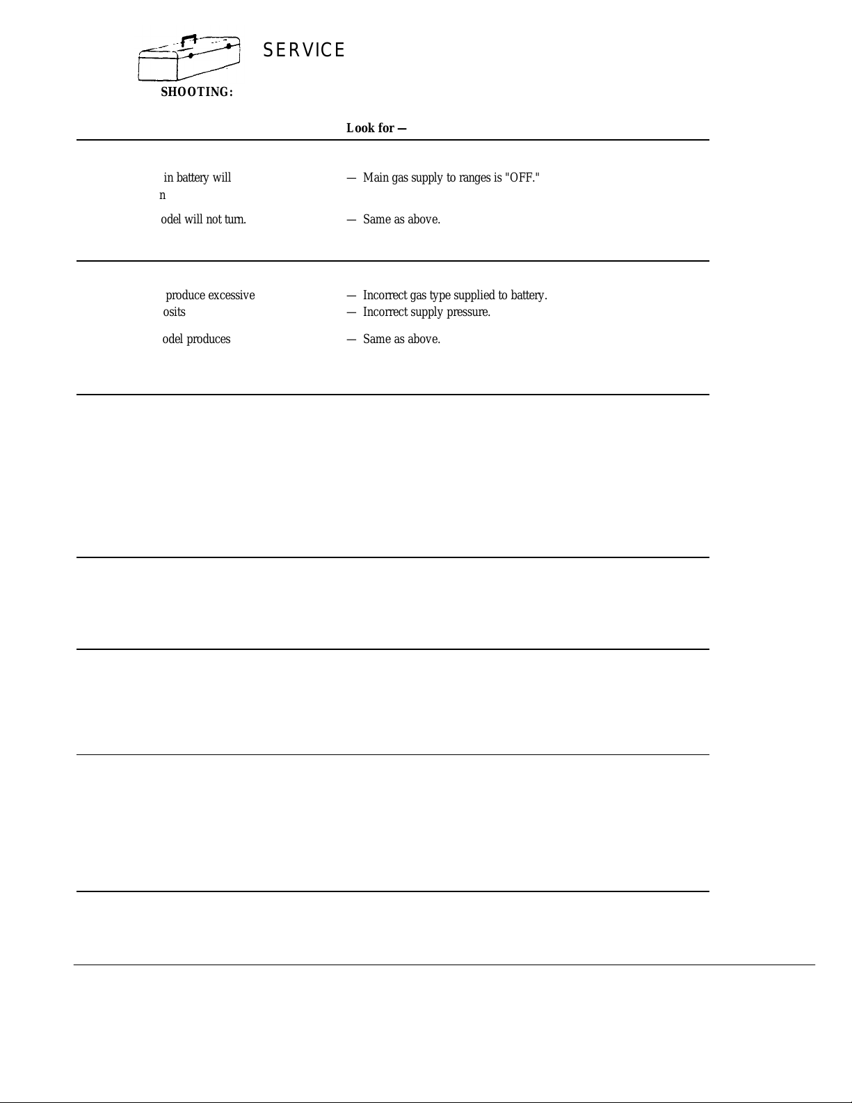
TROUBLE SHOOTING:
Problem Look for —
A. All ranges in battery will — Main gas supply to ranges is "OFF."
B. Counter model will not turn. — Same as above.
A. All ranges produce excessive —
carbon deposits — Incorrect supply pressure.
B. Counter model produces — Same as above.
excessive carbon deposit.
deposits (burners)
Incorrect gas type supplied to battery.
(burners).
Only some pilots produce — Pilot gas not adjusted properly.
excessive carbon deposits — Incorrect pilot orifice.
Burner will — Manual valve in "OFF" position.
Top section pilot will not — Pilot gas not adjusted properly.
— Clogged burner charge port.
— Draft condition.
— Air in gas line.
SECTION THREE — SERVICE
PAGE 2
11-92
Page 6
southbend
A MIDDLEBY COMPANY
Convection Ovens Ranges Steam Kettles Under Fired Broilers
Cook & Hold Convection Ovens Fryers Tilting Braising Pans Salamander Broilers
Bake & Roast Ovens Special & Custom Equipment Cooker/Mixer Kettles Cheese Melters
Pizza Ovens Convection Steamers Floor Model Broilers Counter Top Broilers & Griddles
Page 7
GAS CHAR BROILERS
9161
A MIDDLEBY COMPANY
A product with the Southbend name incorporates the best in durability and low
maintenance. We all recognize however, that replacement parts and occasional
professional service may be necessary to extend the useful life of this unit. When
service is needed, contact a Southbend Authorized Service Agency, or your dealer.
To avoid confusion, always refer to the model number, serial number, and type of
your unit.
southbend
1100 Old Honeycutt Road
Fuq Fuquay-Varina. NC 27526
PART NUMBER 1173265 Rev. 11-92
(919)552FAX (919) 552-9798
(800) 348-2558
Page 8
S E R V I C E
southbend B•U•L•L•E•T•I•N
TO: Southbend Parts & Service Distributors
FROM: Thomas S. Enyeart- CFSP
Director Product Service
DATE: February 5, 1994 BULLETIN #9430
SUBJECT: Valve Change- Floor Model Char Broilers – Propane Gas.
Models SCB-24, SCB-36, SCB-48 and all same with suffix - R
Please insert this Bulletin with the #1173265 Gas Char Broiler owners
manual in the BR- Broiler & Cheese Melters section of your master
Southbend Manual.
Effective December, 1993 Serial #94A and thereafter
Floor Model Char Broiler Valves have been changed. Changing from the old
style to the new style for the first time requires a new knob. The kit is
available for the first time change only. After the original change or on new
style units the valve only can be changed.
DISCONTINUED PART:
1176750 Valve
This part will be available until existing stock is depletedapproximately 18 months. Then it will be obsolete and no longer
available.
NEW PARTS:
1176009 Valve -Hi Low- Propane Gas
When replacing 1076750 for the first time use:
4440401 Valve Replacement Kit- Propane Gas
This kit consists of: (all parts also available individually)
1176009 Valve-Hi Low- Propane Gas
1166011 Valve Knob
NOTE: The new valve can only be used for Propane Gas
For Natural Gas See Bulletin 9429- Part numbers 1176008 &
4440402.
The old valve used a 1160532 Valve Knob which is still available.
1100 Old Honeycutt Rd. • Fuquay-Varina, NC 27526 • (919) 552-9161 • (800) 348-2558 • Fax (919) 552-9798
Parts Service Hotline (800) 54 RANGE (800-547-2643)
Page 9
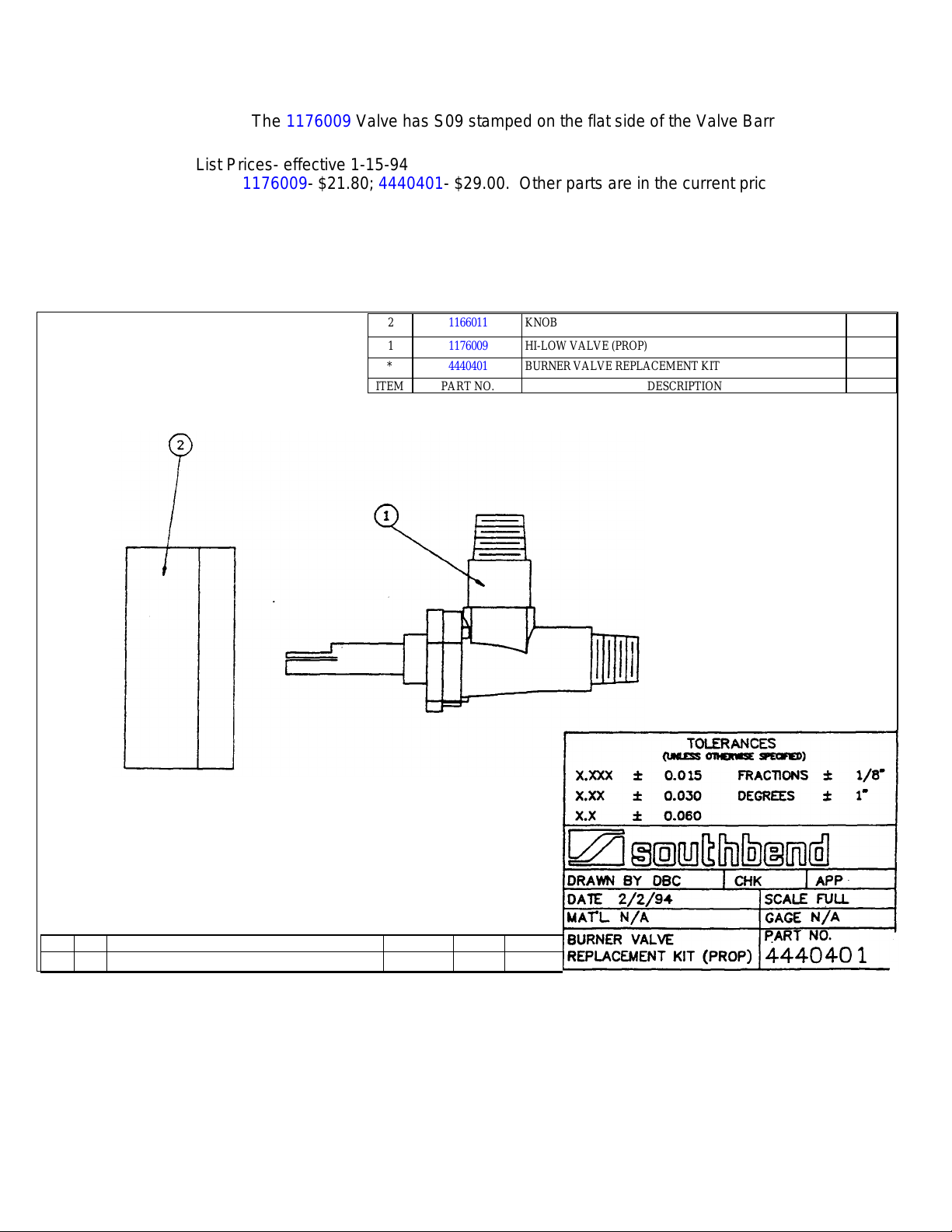
The 1176009 Valve has S09 stamped on the flat side of the Valve Barrel.
ITEM PART NO.
DESCRIPTION
Qty.
List Prices- effective 1-15-94
1176009- $21.80; 4440401- $29.00. Other parts are in the current price list.
TE/dy
2 1166011 KNOB 1
1 1176009 HI-LOW VALVE (PROP) 1
* 4440401 BURNER VALVE REPLACEMENT KIT *
ACAD SIZE A DWGDO NOT HAND ALTER
REV SYM
DRAWING RELEASED
2/2/94
REVISION DATE BY
DBC 94-30
ECN
Page 10

S E R V I C E
southbend B•U•L•L•E•T•I•N
TO: Southbend Parts & Service Distributors
FROM: Thomas S. Enyeart- CFSP
Director Product Service
DATE: February 5, 1994 BULLETIN #9429
SUBJECT: Valve Change- Floor Model Char Broilers – Natural Gas.
Models SCB-24, SCB-36, SCB-48 and all same with suffix - R
Please insert this Bulletin with the #1173265 Gas Char Broiler owners
manual in the BR- Broiler & Cheese Melters section of your master
Southbend Manual.
Effective December, 1993 Serial #94A and thereafter
Floor Model Char Broiler Valves have been changed. Changing from the old
style to the new style for the first time requires a new knob. The kit is
available for the first time change only. After the original change or on new
style units the valve only can be changed.
DISCONTINUED PART:
1076750 Valve
This part will be available until existing stock is depletedapproximately 18 months. Then it will be obsolete and no longer
available.
NEW PARTS:
1176008 Valve -Hi Low- Natural Gas
When replacing 1076750 for the first time use:
4440402 Valve Replacement Kit- Natural Gas
This kit consists of: (all parts also available individually)
1176008 Valve-Hi Low- Natural Gas
1166011 Valve Knob
NOTE: The new valve can only be used for Natural Gas
For Propane Gas See Bulletin 9430- Part numbers 1176009 &
4440401.
The old valve used a 1160532 Valve Knob which is still available.
1100 Old Honeycutt Rd. • Fuquay-Varina, NC 27526 • (919) 552-9161 • (800) 348-2558 • Fax (919) 552-9798
Parts Service Hotline (800) 54 RANGE (800-547-2643)
Page 11

The 1176008 Valve has S08 stamped on the flat side of the Valve Barrel.
ITEM PART NO.
DESCRIPTION
Qty.
List Prices- effective 1-15-94
1176008- $21.80; 4440402- $29.00. Other parts are in the current price list.
TE/dy
2 1166011 KNOB 1
1 1176008 HI-LOW VALVE (NAT) 1
* 4440402 BURNER VALVE REPLACEMENT KIT *
ACAD SIZE A DWGDO NOT HAND ALTER
REV SYM
DRAWING RELEASED
2/2/94
REVISION DATE BY
DBC 94-30
ECN
Page 12

S E R V I C E
southbend B•U•L•L•E•T•I•N
TO: Southbend Parts & Service Distributors
FROM: Thomas S. Enyeart- CFSP
Director Product Service
DATE: February 5, 1994 BULLETIN #9428
SUBJECT: Valve Change- Floor Model Char Broilers – Propane Gas.
Models SCBC-24, SCBC-36, SCBC-48 and all same with
suffix - R
Please insert this Bulletin with the #1173265 Gas Char Broiler owners
manual in the BR- Broiler & Cheese Melters section of your master
Southbend Manual.
Effective December, 1993 Serial #93L and thereafter
Counter Char Broiler Valves have been changed. Changing from the old
style to the new style for the first time requires a new knob. The kit is
available for the first time change only. After the original change or on new
style units the valve only can be changed.
DISCONTINUED PART:
1163552 Valve
This part will be available until existing stock is depletedapproximately 2 years. Then it will be obsolete and no longer
available.
This part was also used on Cheese Melters. See bulletin 9425 & 9426.
NEW PARTS:
1176011 Valve -Hi Low- Propane Gas
When replacing 1163552 for the first time use:
4440399 Valve Replacement Kit- Propane Gas
This kit consists of: (all parts also available individually)
1176011 Valve-Hi Low- Propane Gas
1099121 3/8 CC Nut
1099122 3/8 Ferrule
NOTE: The new valve can only be used for Propane Gas
1100 Old Honeycutt Rd. • Fuquay-Varina, NC 27526 • (919) 552-9161 • (800) 348-2558 • Fax (919) 552-9798
Parts Service Hotline (800) 54 RANGE (800-547-2643)
Page 13

For Natural Gas see Bulletin #9427, Part numbers 1176010 & 4440400.
ITEM PART NO.
DESCRIPTION
Qty.
Both valves use #1173645 Valve Knob.
The 1176011 Valve has S11 stamped on the flat side of the Valve Barrel.
List Prices- effective 1-15-94
1176011- $23.80; 4440399- $26.00; 1099122-$1.00. Other parts are in the
current price list.
TE/dy
3 1099121 3/8 CC NUT
2 1099122 3/8 FERRULE 1
1 1176011 VALVE HI-LOW (PROPANE) 1
* 4440399 BURNER VALVE REPLACEMENT KIT *
REV SYM
DRAWING RELEASED
2/2/94
REVISION DATE BY
DBC 94-30
ACAD SIZE A DWGDO NOT HAND ALTER
ECN
Page 14

S E R V I C E
southbend B•U•L•L•E•T•I•N
TO: Southbend Parts & Service Distributors
FROM: Thomas S. Enyeart- CFSP
Director Product Service
DATE: February 5, 1994 BULLETIN #9427
SUBJECT: Valve Change- Floor Model Char Broilers – Natural Gas.
Models SCBC-24, SCBC-36, SCBC-48, SCBC-60, and all same
with suffix - R
Please insert this Bulletin with the #1173265 Gas Char Broiler owners
manual in the BR- Broiler & Cheese Melters section of your master
Southbend Manual.
Effective December, 1993 Serial #93L and thereafter
Counter Char Broiler Valves have been changed. Changing from the old
style to the new style for the first time requires a new knob. The kit is
available for the first time change only. After the original change or on new
style units the valve only can be changed.
DISCONTINUED PART:
1163552 Valve
This part will be available until existing stock is depletedapproximately 2 years. Then it will be obsolete and no longer
available.
This part was also used on Cheese Melters. See bulletin 9425 & 9426.
NEW PARTS:
1176010 Valve -Hi Low- Natural Gas
When replacing 1163552 for the first time use:
4440400 Valve Replacement Kit- Natural Gas
This kit consists of: (all parts also available individually)
1176010 Valve-Hi Low- Natural Gas
1099121 3/8 CC Nut
1099122 3/8 Ferrule
NOTE: The new valve can only be used for Natural Gas
1100 Old Honeycutt Rd. • Fuquay-Varina, NC 27526 • (919) 552-9161 • (800) 348-2558 • Fax (919) 552-9798
Parts Service Hotline (800) 54 RANGE (800-547-2643)
Page 15

TE/dy
For Propane Gas see Bulletin #9428, Part numbers '176008 &
4440402.
Both valves use #1173645 Valve Knob
The 1176010 Valve has S10 stamped on the flat side of the Valve
Barrel.
List Prices- effective 1-15-94
1176010- $23.80; 4440400- $26.00.; 1199122- $1.00. Other parts are in the
current price list.
Page 16

S E R V I C E
southbend B•U•L•L•E•T•I•N
TO: Southbend Parts & Service Distributors
FROM: Thomas S. Enyeart- CFSP
Director Product Service
DATE: February 5, 1994 BULLETIN #9403
SUBJECT: Correction/ Clarification of Gas Pressure Regulators used on
Char Broilers. Models SCB & SCBC.
Please insert this Bulletin with the #1173265 Gas Char Broiler owners
manual in the BR- Broiler section of your master Southbend Manual.
When the owners manual was printed there was an error on pressure
regulator usage. The following corrects this error and clarifies the usage.
For Sectional (Front Manifold) Char Broilers – Models SCB-24, 36, 48
#1167782 Pressure Regulator – 1” – Natural Gas – Set at 6”wc
#1167783 Pressure Regulator – 1” – Propane Gas – Set at 10”wc
For Counter Char Broilers – Models SCBC-24, 36, 48, 60
#1160205 Pressure Regulator – ¾” Natural Gas – Set at 5”wc
#1160206 Pressure Regulator – ¾” Propane Gas – Set at 10”wc
Note: Part #1160205 is used on other units and is a Mandatory Distributor
Stock Part.
TE/dy
1100 Old Honeycutt Rd. • Fuquay-Varina, NC 27526 • (919) 552-9161 • (800) 348-2558 • Fax (919) 552-9798
Parts Service Hotline (800) 54 RANGE (800-547-2643)
Page 17

GAS CHAR BROILER
A
B
H
J
(457)
(737)
(559)
(991)
(737)
(559)
(991)
.81
cu. m.
(457)
(737)
(559)
(991)
?SCBC
-
24AR
(
737)
(559)
(991)
(737)
(559)
(991)
(330)
(737)
(559)
( ) =
Millimeters
( )=
Millimeters
INSTALLATION
FRONT MANIFOLD AND FREE STANDING TYPES
Floor Model Units - Models SCB-24, 36, 48 SPECIFICATIONS
SIDE VIEW FRONT VIEW TOP VIEW
DIMENSIONS:
EXTERIOR 1 ¼” MAN.PIPE 1" REAR GAS
MODEL
WIDTH
DEPTH
C D E F G
TOTAL
I
CK.TOP
K L M N
SCB24
SCB-24R
SCB-36
SCB-36R
SCB-48
SCB-4R
24"
(610)
36"
(914)
48”
(1219)
36"
(914)
36-
(914)
36"
(914)
—
—
—
31¾”
(806)
31¾”
(806)
31¾”
(806)
33"
(838)
33"
(838)
33"
(838)
3"
(76)
3"
(76)
3”
(76)
COUNTER UNITS - Models SCBC-24, 36, 48, 60
SIDE VIEW FRONT VIEW TOP VIEW
DIMENSIONS:
MODEL
? SCBC-24
? SCBC-24R
? SCBC-36
?SCBC-36R
?SCBC-48
?SCBC-48R
?SCBC-24A
?SCBC-36A
?SCBC-36AR
?SC8C-48A
?SCBC-48AR
?SCBC-60A
?SCBC-60AR
EXTERIOR CRATE SIZE
WIDTH DEPTH HEIGHT
A B C D E F G H 1 J
24"
(610)
36”
(914)
48”
(1219)
24”
(610)
36”
(914)
48"
(1219)
60"
(1524)
30"
(762)
30"
(762)
30"
(762)
30”
(762)
30"
(762)
30"
(762)
30”
(762)
18”
18”
(457)
18”
18”
(457)
18”
(457)
18”
(457)
18"
(457)
5"
(127)
5"
(127)
5”
(127)
5”
(127)
5”
(127)
5"
(127)
5"
(127)
Cooking
Surface
13”
(330)
13"
(330)
13"
(330)
13”
(330)
13”
(330)
13”
13"
(330)
29"
29"
29"
29"
29"
29"
29"
(737)
27 7/8”
(708)
27 7/8”
(708)
27 7/8”
(708)
27 7/8”
(708)
27 7/8”
(708)
27 7/8”
(708)
27 7/8”
(708)
17"
(430)
17"
(430)
17"
(430)
22"
22"
22”
22”
22"
22"
22"
(559)
36"
(914)
36"
(914)
36"
(914)
¾” Gas
Connection
2 3/8”
(60)
2 3/8”
(60)
2 3/8”
(60)
2 3/8”
(60)
2 3/8”
(60)
2 3/8”
(60)
2 3/8”
(60)
6"
(152)
6"
(152)
6"
(152)
1 ½”
(38)
1 ½”
(38)
1 ½”
(38)
1 ½”
(38)
1 ½”
(38)
1 ½”
(38)
1 ½”
(38)
30"
(762)
30"
(762)
30"
(762)
Burners
(BTU ea)
2ea.
(40.000)
3ea.
(40,000)
4ea.
(40.000)
2ea.
(36,000)
3ea.
(36.000)
4ea.
(36.000)
5ea.
(36.000)
33¾”
(857)
33¾”
(857)
33¾”
(857)
WIDTH DEPTH HEIGHT
31"
(787)
55"
(1397)
55"
(1397)
31"
(787)
55"
(1397)
55"
(1397)
67"
(1702)
39"
39-
39"
39"
39"
39"
(991)
39"
(991)
33½”
(851)
33½”
(851)
33½”
(851)
24"
(610)
24"
(610)
24"
(610)
24"
(610)
24”
(610)
24”
(610)
24"
(610)
SECTION ONE — INSTALLATION
14"
14"
14"
CUBIC
VOLUME
16.8 cu. ft.
.47 cu. m.
28.9cu.ft.
28.9cu.ft.
.81 cu.m.
16.8cu.ft.
.47 cu. m.
28.9cu.ft.
.81 cu. m.
28.9cu.ft.
.81 cu.m.
2½”
(63)
2½”
(63)
2½”
(63)
(356)
(356)
(356)
CHAR BROILERS
CRATED
WEIGHT
240 Ibs. 109.1 kg.
200 Ibs. 90.9kg.
350 Ibs. 159.1kg.
290 Ibs. 131.8kg.
425 Ibs. 193.2kg.
345 Ibs. 156.8 kg.
240 Ibs. 109.1 kg.
200 Ibs. 90.9kg.
350 Ibs. 159.1kg.
290 Ibs. 131.8kg.
425 Ibs. 193.2kg.
345 Ibs. 156.8kg.
PAGE 1
Page 18

INSTALLATION
WARNING: THESE PROCEDURES MUST BE FOLLOWED BY QUALIFIED PERSONNEL OR
WARRANTY WILL BE VOIDED.
GENERAL:
The installation must conform with local codes, or in the absence of local codes, with the National Fuel Gas
Code, ANSI Z223.1 - Latest Edition. Canadian installation must comply with CAN/CGA-B 149.1 Natural Gas
Installation Code, Code CAN/CGA-B 149.2 Propane Installation Code.
These models are design certified for operation on Natural or Propane gases.
The appliance should be connected ONLY to the type of gas for which it is equipped. All Southbend equipment
is adjusted at the factory.
NOTE: Check type of gas on serial plate.
Models: SCB-Series - serial plate located left front comer on bottom inside lower compartment.
Models: SCBC-Series - remove front control panel. Serial plate attached in the center on the compartment
front shield to unit.
NOTE: Each SCB-Series Broiler is a complete unit with an individual W NPT manifold across its entire width.
Units can be batteried by joining the unions at the ends of the manifolds. This manifold is not equipped
directly with a pressure regulator. However, the manifold must be connected with an adequately sized gas
appliance pressure regulator adjusted to supply a pressure to this manifold as marked on the serial plate; 6"
W.C. for natural gas and 10" W.C. for propane gas. In addition, the pressure regulator must meet the
following requirements:
1. The pressure regulator installed should be certified by a nationally recognized testing agency.
2. The regulator must have a maximum regulation capacity for the total connected load.
3. The regulator must have a pressure adjustment range to allow adjustment to the manifold pressure on the
appliance rating plate.
4. Unless the manifold pressure of all connected appliances is the same, a separate regulator must be supplied
for each unit(s) to indicate unit or units having differing manifold pressures.
5. If applicable, the vent line from the gas appliance pressure regulator shall be installed to the outdoors in
accordance with local codes or, in the absence of local codes, with the National Fuel Gas Code, ANSI Z23.1 Latest Edition. Canadian installation must comply with CAN/CGA-B 149.1 Natural Gas Installation Code,
Code CAN/CGA-B149.2 Propane Installation Code.
An adequate gas supply is imperative. Undersized or low pressure lines will restrict the volume of gas required for
satisfactory performance. A steady supply pressure, between 7" W.C. and 8" W.C. for natural gas and 11" W.C.
and 12" W.C. for propane gas is recommended. With all units operating simultaneously, the manifold pressure on
all units should not show any appreciable drop. Fluctuations of more than 25% on natural and 10% on propane
gas will create pilot problems and affect burner operating characteristics. Contact your gas company for correct
supply line sizes.
As an option, the unit may be supplied with a rear gas connection. The pipe size of this connection is one inch.
Unless otherwise specified, this connection is welded to the right side of the manifold.
NOTE: Each SCBC-Series Counter Broiler is a complete unit with an individual ¾” NPT supply connection at
the rear. An adequate gas supply is imperative. Undersized or low pressure lines will restrict the volume of gas
required for satisfactory performance. A pressure regulator, which is provided with each unit, is set to maintain
a 4" W.C. manifold pressure for natural gas and a 10" W.C. manifold pressure for propane gas. However, to
maintain these conditions the pressure on the supply line, when all units are operating simultaneously, should
not drop below 7" W.C. for natural gas or 11” W.C. for propane gas.
A 1/8” pressure tap is located on the manifold of each unit.
All pipe joints should be tested for leaks with a soap and water solution before operating the unit. The test
pressure should not exceed 14" W.C.
CAUTION: THIS APPLIANCE AND ITS INDIVIDUAL SHUTOFF VALVE MUST BE DISCONNECTED
FROM THE GAS SUPPLY PIPING SYSTEM DURING ANY PRESSURE TESTING OF THAT
SYSTEM AT TEST PRESSURES IN EXCESS OF 112 PSIG (3.45 kPa).
THIS APPLIANCE MUST BE ISOLATED FROM THE GAS SUPPLY PIPING SYSTEM BY CLOSING
ITS INDIVIDUAL MANUAL SHUTOFF VALVE DURING ANY PRESSURE TESTING OF THE GAS
SUPPLY PIPING SYSTEM AT TEST PRESSURES EQUAL TO OR LESS THAN 112 PSIG (3.45
kPa).
CHAR BROILERS
SECTION ONE — INSTALLATION
PAGE 2
Litho in U.S.A.
11-92
Page 19

INSTALLATION
WARNING: THESE PROCEDURES MUST BE FOLLOWED BY QUALIFIED PERSONNEL
OR WARRANTY WILL BE VOIDED.
EXHAUST FANS AND CANOPIES:
Canopies are set over ranges, ovens, etc., for ventilation purposes. It is recommended that a canopy extend 6" past appliance
and be located 6'6" from the floor. Filters should be installed at an angle of 45 degrees or more with the horizontal. This
prevents dripping grease and facilitates collecting the run-off grease in a drip pan, usually installed with a filter. A strong
exhaust fan tends to create a vacuum in the room and may interfere with burner performance or may extinguish pilot flames.
Fresh air openings approximately equal to the fan area will relieve such vacuum. In case of unsatisfactory performance on any
appliance, check with the exhaust fan in the "OFF" position.
WALL EXHAUST FAN: Should be installed at least 2 feet above the vent opening at the top of the backsplash.
NOTE: Be sure to inspect and clean ventilation system according to the ventilation equipment manufacturers instructions.
CLEARANCES
Minimum clearances from combustible construction are: (Canadian installations only)
MODEL TYPE SIDES REAR
FLOOR MODELS 12 IN. 6 IN.
COUNTER MODELS 12 IN. 6 IN.
Minimum clearances from non-combustible construction are: )
MODEL TYPE SIDES REAR
ALL MODELS 0 IN. 0 IN.
WARNING: All units must be installed in such a manner that the flow of combustion and ventilation air are not obstructed.
Provisions for an adequate air supply must also be provided. Do not obstruct the front of the unit at the top by the control
panel.
NOTE: No additional clearance from the sides and back is required for service, as the units are serviceable from the front.
FOR FLOOR MODELS - LEGS OR OPTIONAL CASTERS:
1. A set of legs or casters are packed in the unit. A threaded receptacle is
fastened to the base frame at each corner. Each leg or caster has a similar
mating thread.
2. Raise unit sufficiently to allow legs or casters to be screwed into the
receptacles. For safety, "shore up" and support the unit with an adequate
blocking arrangement strong enough to support the load.
3. Lower unit gently. Never drop or allow the unit to fall.
4. The legs or casters can be adjusted to overcome an uneven floor.
5. After the unit has been leveled, tighten the lock nuts.
WARNING: For an appliance equipped with casters, the installation shall be made with a connector that complies with the
standard for connectors for movable gas appliances, ANSI Z21.69-1987, CAN/CGA-6.10-88 and a quick-disconnect device
that complies with the standard for quick-disconnect devices for use with gas fuel, ANSI Z21.41-1978, and addenda,
Z21.41a.l981, Z21.41b.l983 and CAN/CGA-6.10-88. Adequate means must be provided to limit the movement of the
appliance without depending on the connector and the quick-disconnect device or its associated piping to limit the appliance
movement.
WARNING: Appliances equipped with casters have been installed with a restraint to limit their movement to prevent damage
to the gas supply connecting system. If disconnection of this restraint is necessary to move the appliance for cleaning, etc.,
reconnect it when the appliance is moved to its originally installed position.
SECTION ONE — INSTALLATION
CHAR BROILERS
PAGE 3
Page 20

INSTALLATION
CHAR BROILERS
Litho in U
-
S.A.
WARNING: THESE PROCEDURES MUST BE FOLLOWED BY QUALIFIED PERSONNEL
OR WARRANTY WILL BE VOIDED.
TO INSTALL COUNTER MODELS:
1. Seal to counter top with sealer such as G.E. or DOW Coming RTV type sealant. (Consult local code for exact
requirements.)
INSTRUCTIONS: To install Legs on Counter Models
1. Remove the BASIC Unit from the container.
2. CAREFULLY place the unit on its BACK.
3. Four NSF approved LEGS are packed with the unit.
4. REF: Sketch below:
A threaded RECEPTACLE (R) is attached to the underside of the bottom, at each corner.
Each leg has a threaded STUD (S).
Tighten the stud on each leg into a receptacle. Secure with a wrench on the hexagon section of the leg.
Each leg has its own NSF approved leveling FOOT (L). By adjusting these feet, the proper combination can be
achieved whereby the unit will be level and steady.
CAUTION: ONLY NON-COMBUSTIBLE COUNTERS ARE TO BE USED TO SUPPORT THESE UNITS
GAS CONNECTION:
On all threaded connections, the pipe joint compound must be approved for use with natural and LP gas. L
INDIVIDUAL UNITS:
1. Remove valve panel.
2. Use a long spirit level four ways; across the front top rail and rear collar plate, and along each edge.
3. A. For units that will not use the rear gas connection, connect the gas supply to the right or left side of
the manifold. Be sure to cap the unused side and the rear gas inlet.
B. For units that will use the rear gas connection, the gas supply to the unit will be made at the right
rear. Be certain both ends of the manifold are capped.
C. For counter units, a ¾” NPT gas supply connection is located at the right side of rear, when you are
facing rear of the unit.
4. Turn off all burner valves.
5. Turn on gas supply and immediately check all gas connections for leaks. Use soapy water only. Never use
an open flame.
6. Put valve panel back onto the unit.
7. Proceed to "MOUNTING SHELF OR BACKSPLASH INSTALLATION INSTRUCTIONS," if
applicable.
SECTION ONE — INSTALLATION
PAGE 4
11-92
Page 21

INSTALLATION
WARNING: THESE PROCEDURES MUST BE FOLLOWED BY QUALIFIED PERSONNEL
OR WARRANTY WILL BE VOIDED.
ASSEMBLY OF BATTERY - FLOOR MODEL UNITS:
1. Position the center range of the battery and carefully level unit. Use a long spirit level four ways; across front
top rail and the rear collar plate, and along each edge.
2. Remove all valve panels. Mark, so they will be returned to their respective unit.
3. Bring up adjacent units, level by same method and by using the center unit as reference. Match front rails and
rear collar plates. When battery is set on a masonry base and legs are not used, shims may be used. Special
attention should be given to Fry Top ranges to allow proper drainage on griddles.
4. Where Spreader Plates are installed, refer to Sectional Battery Component Assembly Instructions supplied
with each unit.
5. Connect units together by mating the unions. Make unions just HAND TIGHT at this time.
6. Starting at the center and working toward the ends, tighten each union gradually, going from one to another,
until all are finally tight. A special thin wrench, which fits the union nut, is provided with each battery, or a
chain wrench can be used.
7. Connect gas supply at right, left, or both ends. When a Spreader Plate with a "Tee" connection is inserted in a
battery, the gas supply may be connected at this point. Ranges with rear connections may also be used in this
respect. If five or more units are battened, more than one supply line should be used. Each supply line should
have a readily accessible, approved hand shutoff valve.
8. "Open" ends of the manifold must be capped.
9. Turn off all burner valves.
10. Turn on gas supply and immediately check all the unions for leaks. USE SOAPY WATER ONLY FOR
TESTING ON ALL GASES. NEVER USE AN OPEN FLAME TO CHECK FOR GAS LEAKS.
11. When entire gas system has been proved, turn off gas supply during additional installation.
12. A filler to cover the "gap" between the range fronts and tops is provided. Refer to Sectional Battery
Component Assembly Instructions supplied with each unit.
ASSEMBLY OF COUNTER MODELS:
1. Each Char Broiler is a complete unit with an individual %" NPT supply connection at the rear. A %" manual
gas shutoff valve is recommended at the gas supply inlet for complete shutdown. Standard pipe fittings are
required.
2. The regulator shipped with the unit must be installed at the gas supply inlet. Be sure regulator is connected so
that the gas flow is in the same direction as the arrow on the bottom of the regulator.
3. The manifold pressure must be maintained at the pressure marked on the serial plate; 4" W.C. for natural gas
and 10" W.C. for propane gas.
4. If applicable, the vent line from the gas appliance pressure regulator shall be installed to the outdoors in
accordance with local codes or, in the absence of local codes, with the National Fuel Gas Code, ANSI Z223.1Latest Edition. Canadian installation must comply with CAN/CGA-B 149.1 Natural Gas Installation Code,
Code CAN/CGA-B149.2 Propane Installation Code.
WARNING: IN THE EVENT A GAS ODOR IS DETECTED, SHUT DOWN THE EQUIPMENT AT
THE MAIN SHUTOFF VALVE AND CONTACT THE LOCAL GAS COMPANY OR GAS
SUPPLIER FOR SERVICE.
CHAR BROILERS
SECTION ONE — INSTALLATION
PAGE 5
Page 22

INSTALLATION
1.
Front panel "A" is fastened with
CHAR BROILERS
Litho in U.S.A.
WARNING: THESE PROCEDURES MUST BE FOLLOWED BY QUALIFIED PERSONNEL
OR WARRANTY WILL BE VOIDED.
ASSEMBLY OF FREE STANDING MODELS:
1. Each Char Broiler is a complete unit with an individual 1" NPT supply connection at the rear. A 1" manual ga s shutoff
valve is recommended at the gas supply inlet for complete shutdown. Standard pipe fittings are required.
2. The regulator shipped with the unit must be installed at the gas supply inlet. Be sure regulator is connected so that the gas
flow is in the same direction as the arrow on the bottom of the regulator.
3. The manifold pressure must be maintained at the pressure marked on the serial plate; 6" W.C. for natural gas and 10" W.C.
for propane gas.
4. If applicable, the vent line from the gas applia nce pressure regulator shall be installed to the outdoors in accordance with
local codes or, in the absence of local codes, with the National Fuel Gas Code, ANSI 7333.1-Latest Edition. Canadian
installation must comply with CAN/CGA-B149.1 Natural Gas Installation Code, Code CAN/CGA-B149.2 Propane
Installation Code.
MOUNTING BACKSPLASH
INSTALLATION
INSTRUCTIONS
six (6) sheet metal screws.
Remove screws and panel will
come loose.
2. Remove nuts and lock washer
from collar plate studs "C" on
unit.
3. Lower the backsplash on to unit
allowing studs "C" to enter holes
in the shelf bracket. Secure shelf
bracket "B" with nuts and lock
washers that were removed in
instruction No. 2.
Fig. 1
NOTE: BACKSPLASH WILL POSSIBLY
BE MOUNTED ON SCBCs.
FRONT FILLER MOUNTING PROCEDURE
FIG 2. - FLAT-TYPE FRONT FILLER
(#1692 Black, #1692SS Stainless Steel)
APPLICATION: Char Broiler battened to a Fryer or Cabinet Based Unit.
MOUNTING PROCEDURE:
Align filler equally spaced over each unit. Drill securing holes with a #38
drill, using pre-punched holes in filler as a guide and secure with #4 x 3/8
sheet metal screws.
Fig. 2
WARNING: TUBULAR GAS LINES ARE LOCATED ON THE LEFT SIDE OF THE STANDARD
OVEN BASE UNITS BEHIND THE FILLER SECURING SCREW AREA. IF HOLES NEED TO
BE DRILLED, CARE MUST BE TAKEN AND INSPECTION MADE TO ENSURE GAS LINES
ARE NOT PUNCTURED.
WARNING: IN THE EVENT A GAS ODOR IS DETECTED, SHUT DOWN THE EQUIPMENT AT
THE MAIN SHUTOFF VALVE AND CONTACT THE LOCAL GAS COMPANY OR GAS
SUPPLIER FOR SERVICE.
SECTION ONE — INSTALLATION
PAGE 6
11-92
Page 23

INSTALLATION
WARNING: THESE PROCEDURES MUST BE FOLLOWED BY QUALIFIED PERSONNEL
OR WARRANTY WILL BE VOIDED.
Fig. 3
APPLICATION: Char Broiler batteried with a Standard Oven Base
APPLICATION: Char Broiler on Left batteried with a
MOUNTING PROCEDURE:
If mounting holes are pre-drilled, remove screws, attach filler and secure with same screws. If mounting holes are not predrilled, or if pre-drilled holes do not align properly, drill holes using an 11/64” (.171 dia.) drill and secure with #10 x ½
slotted truss head sheet metal screws.
FIG. 3 - L.TYPE FRONT FILLER
Unit.
(#1146101 Black, #1146103 Stainless Steel for
Oven Base Unit on Right)
(#1146100 Black, #1146102 Stainless Steel for
Oven Base Unit on Left)
Convection Oven Base Unit on the Right.
(#1167010 Black, #1167011 Stainless Steel)
Fig. 4
FIG. 4 - L-TYPE FRONT FILLER
(#1166951 Black, #1166952 Stainless
Steel for Convection Oven Base Unit on left)
APPLICATION: Convection Oven Base Unit on left
and Char Broiler on right.
MOUNTING PROCEDURE
1. RIGHT SIDE OF THE CONVECTION OVEN BASE UNIT AT CONTROL PANEL - Loosen the two screws on the
right side of the front filler panel. Align the two slots in the front filler with the two screws. Push filler in until it is flush
with the front of the front filler panel and retighten the two screws.
2. For Standard Oven Base Units and Convection Oven Base Units being batteried against the Convection Oven Base Unit
right side, the factory will supply the single unit type left front trim. P/N 1136006 Black and 1136007 Stainless Steel for
Standard Sectional Units and P/N 1166809 Black and 1166810 Stainless Steel for Convection Oven Sectional Units.
3. Slide adjacent unit up against Convection Oven Sectional and forward up against front filler.
NOTE: For Cabinet Base Units
Left Front Trim Not Req'd.
WARNING: TUBULAR GAS LINES ARE LOCATED ON THE LEFT SIDE OF THE STANDARD
OVEN BASE UNITS BEHIND THE FILLER SECURING SCREW AREA. IF HOLES NEED TO BE
DRILLED, CARE MUST BE TAKEN AND INSPECTION MADE TO ENSURE GAS LINES ARE
NOT PUNCTURED.
WARNING: IN THE EVENT A GAS ODOR IS DETECTED, SHUT DOWN THE EQUIPMENT AT
THE MAIN SHUTOFF VALVE AND CONTACT THE LOCAL GAS COMPANY OR GAS
SUPPLIER FOR SERVICE.
SECTION ONE — INSTALLATION
CHAR BROILERS
PAGE 7
Page 24

INSTALLATION
1172406
Drain Cabinet
Char Broiler
Fig. 5
Right Side Show
END TRIM MOUNTING PROCEDURE (Fig. 5)
(Left Side Opposite)
APPLICATION: Sectional Battery Units with Capped Manifold.
(#1072501 Black, #1072503 Stainless Steel Left End Trim)
(#1072500 Black, #1072502 Stainless Steel Right End Trim)
(#1073399 End Pipe Cap)
NOTE: Sectional type units are normally shipped with requested optional end trim attached to body side.
1. Position end trim to the underside of the front rail, tight against front and top.
2. Using the pre-punched holes in the end trim as a guide, drill (3) 1/8" (.125 dia.) holes and secure with (3) ff8 x % sheet
metal screws.
Slip-on filler will be supplied to seal unit top to unit top in case of spillage.
Types of fillers supplied will be:
Top fillers, except "U" channel range to range filler will be labeled to identify adjoining unit usage.
PART NUMBER UNIT ON LEFT
1172399 Char Broiler
1172401 Char Broiler
1172403 Char Broiler
1172405 Char Broiler
1172407 Char Broiler
1172495 Char Broiler
1172400 Any Range
1172402 Fryer 14"
1172404 Fry Top Range
1172408 Battery Type Broiler
1172496 Fryer 18"
CHAR BROILERS
SECTION ONE — INSTALLATION
PAGE 8
TOP FILLERS FOR BATTERY INSTALLATIONS
Char Broiler to Range Char Broiler to Drain Cabinet
Char Broiler to Fryer Battery Type Broiler to Char Broiler
Char Broiler to Fry Top Range
UNIT ON RIGHT
Any Range
Fryer 14"
Fry Top Range
Drain Cabinet
Battery Type Broiler
Fryer 18"
Char Broiler
Char Broiler
Char Broiler
Char Broiler
Char Broiler
Litho in
U.S.A. 11-92
Page 25

INSTALLATION
FRONT RAIL
GRATE
24 1 36 1
FLEX BROILER CONFIGURATIONS
SUPPORT
24" — 1172204
36" — 1172205
48" — 1172206
*NOTE: Maximum number of griddles per Char Broiler are:
OPTIONAL GRIDDLE MAY BE USED IN TWO WAYS AS FOLLOWS:
1. Placed on top of grids.
2. In place of two grids.
Unit Width
(in.) Griddles
48 2
60 2
Number of
CHAR BROILERS
SECTION ONE — INSTALLATION
PAGE 9
Page 26

OPERATION
CHAR BROILERS
Litho in U.S.A.
WARNING: THESE PROCEDURES MUST BE FOLLOWED BY QUALIFIED PERSONNEL
OR WARRANTY WILL BE VOIDED.
WARNING: For an appliance equipped with casters, the installation shall be made with a connector that complies with the
standard for connectors for movable gas appliances, ANSI Z21.69-1987, CAN/CGA -6.10-88 and a quick-disconnect device
that complies with the standard for quick-disconnect devices for use with gas fuel, ANSI Z21.41-1978, and addenda,
Z21.41a.l981, Z21.41b.l983 and CAN/CGA-6.10-88. Adequate means must be provided to limit the movement of the
appliance without depending on the connector and the quick-disconnect device or its associated piping to limit the appliance
movement.
WARNING: Appliances equipped with casters have been installed with a restraint to limit their movement to prevent
damage to the gas supply connecting system, if disconnection of this restraint is necessary to move the appliance for
cleaning, etc., reconnect it when the appliance is moved to its originally installed position.
Before turning main gas supply on, make sure all control valves are in the "OFF" position.
All units are adjusted at the factory. On new installations start up with the top burner of the unites) furthest from
the gas input to the manifold. This will purge the system of air. Turn gas supply "ON."
1. Models:
A. Models: SCB-Series
Unit is set with each burner at 40,000 BTU/hour at the factory prior to shipment, and should bum
reasonably close to the desired flame. Natural gas manifold pressure is 6" W.C. Propane gas manifold
pressure is 10" W.C.
B. Models: SCBC-Series
Unit is set with each burner at 40,000 BTU/hour at the factory prior to shipment, and should bum
reasonably close to the desired flame. Natural gas manifold pressure is 4" W.C. Propane gas manifold
pressure is 10" W.C.
C. Models: SCBC-Series with suffixes A, AR
Unit is set with each burner at 36,000 BTU/hour at the factory prior to shipment, and should burn
reasonably close to the desired flame. Natural gas manifold pressure is 4" W.C. Propane gas manifold
pressure is 10" W.C.
2. Pilot Lighting Instructions:
A. Set pilot valve with screwdriver to provide ½” flame by turning counterclockwise.
B. Light each pilot with match or taper.
C. Turn desired burner valve "ON."
D. To shut down, turn burner valve to "OFF." If pilot shutdown is desired, turn pilot valve(s) clockwise until
tight.
E. Do not attempt to relight for 5 minutes after shutdown.
3. The main burner flame should be 1" to 1 ½” high on natural gas and approximately ½” to 5/8” on propane
gas. Air can be adjusted by opening or closing air shutter slightly. See "ADJUSTMENTS."
4. Reinstall grate support, drip shield, grates and ceramics or on radiant model the radiants. On ceramic models
make sure ceramics are placed at random, not more than one layer thick, and with grates covered as
completely as possible. Turn flames on full for 15-20 minutes; bottom of ceramics should glow red. Once
preheated, the low valve setting should maintain cooking temperatures.
SECTION TWO — USER'S GUIDE
PAGE 2
CAUTION: IF YOU SMELL GAS DURING THE LIGHTING PROCEDURE, IMMEDIATELY SHUT
OFF THE GAS SUPPLY UNTIL THE LEAK HAS BEEN CORRECTED.
11-92
Page 27

OPERATION
5. Putting Broiler Into Use:
A. Heating — Be sure all standing pilots are lit. Turn on the number of burners desired to the full "ON" position. After
15-20 minutes flame can be turned back to maintain enough heat to keep the bottom of the coals or radiants hot.
These ceramic coals or radiants will be at broiling temperature throughout, giving off the radiant heat which is so
necessary to provide fast broiling.
B. Adjustment of Top Broiler Grid — To tilt, pull upon the back of the grid to place it in the tilt position. Normal
broiling position is the tilted position, and we recommend that this be used most of the time. The tilt angle allows the
fats rendered off during broiling of steaks, chops and hamburgers to run off into grease trough, thus eliminating
excess flaring of fats and accompanying smoke. The flat position should be used for heating on the top, or for continuous hot dog or sausage work. Fats dripping down into the fire will burn up on the meat and help to give it that
"special" flavor that is not only desirable but should occur. Steaks and chops, being fattier than other meats, will
naturally have the most flaring up. The angle will drain off sufficient fats to eliminate severe flares while providing
desirable broiling results.
C. Broiling:
Once the fire is hot enough, put your steak on the broiler. .. make sure both sides of the steak are seared to retain
maximum juice. This fast cooking is one of the secrets of successful steak broiling and gives your steaks that special
"outdoor" flavor. A 1 "-thick, rare steak should take approximately 8 minutes; adjust your timing according to
thickness of steak and amount of doneness required.
The Char Broiler is designed so that the rear 2/3 of the broiler grid is much hotter than the front 1/3. Use this to your
advantage — broil rare meats at the back quickly; medium and well-done meats close to the front, more slowly.
Remember, to cook meat properly you must have two essential things: Time and Heat — your Char Broiler gives
you a choice of heat intensity — you choose your own timing.
If you have several steaks to be finished in different degrees of doneness, move the finished rare steaks to the very
front where they will stay warm without cooking while medium and well-done steaks are finishing.
These suggestions apply equally to other food products. We sincerely hope that this information will be helpful to
you in the successful and profitable use of your broiler, and we are happy to have this opportunity of serving you.
SECTION TWO — USER'S GUIDE
CHAR BROILERS
PAGE 3
Page 28

MAINTENANCE
Litho in U.S.A.
WARNING:
ADJUSTMENTS AND SERVICE WORK MAY BE PERFORMED ONLY BY A QUAU. FIED
TECHNICIAN WHO IS EXPERIENCED IN, AND KNOWLEDGEABLE WITH, THE
OPERATION OF COMMERCIAL GAS COOKING EQUIPMENT. HOWEVER, TO ASSURE
YOUR CONFIDENCE, CONTACT YOUR AUTHORIZED SERVICE AGENCY FOR RELIABLE
SERVICE, DEPENDABLE ADVICE OR OTHER ASSISTANCES, AND FOR GENUINE
FACTORY PARTS.
CLEANING BROILER TOP GRID:
Daily — Brush regularly with a wire brush followed by wiping with a cloth, to prevent accumulation of carbon.
The grids should be cleaned regularly since this is where the rendered fat from the broiling operation runs off. If
accumulation of carbon develops here, the fats will drip from the points of carbon instead of running all the way
down to the end of the grid into the grease trough. To expect the best performance, your equipment must be
maintained in good condition, and cleaned daily. Naturally, the periods for this care and cleaning depend on the
amount and degree of usage.
Weekly — The grid should be removed at least weekly and scrubbed thoroughly. Done regularly this is an easy
job, but if neglected strong methods must be used to get it clean.
CLEANING CAST-IRON GRATES AND CERAMIC COALS:
(MODELS WITHOUT R SUFFIX)
The cast-iron grates receive the greatest amount of wear due to the extreme heat required for char broiling. Tb
insure longest possible life, coals and grates should be removed every few days, clinkers removed, and grates
brushed.
CAUTION: DO NOT OVERLOAD WITH COALS - ONE LAYER PLACED AT RANDOM IS
SUFFICIENT.
When grates become too badly warped they should be replaced.
CLEANING RADIANTS: (MODELS WITH R SUFFIX)
The radiants receive a great amount of wear due to excessive heat and drippings from cooking. Clean the radiants
every few days by placing in dishwasher.
CLEANING BURNERS:
Burners should be cleaned weekly. Remove and clean with wire brush. If burner ports are clogged, ream with stiff
wire. Due to intense heat it's possible burners will warp. Warped burners should be replaced immediately.
CLEANING CRUMB TRAY AND GREASE PAN:
There are 2 pans in the bottom of the unit. One is to catch grease (in the far left-hand comer of the broiler) and the
other is to catch crumb drippings from the broiler. The large pan, or crumb tray, should be removed every couple
of days and washed thoroughly. The small pan, or grease drawer, should be removed frequently to empty
accumulated grease and avoid overflow. This should be done while warm so that the grease is in a liquid state. The
shield over the grease protects it from the intense radiant heat, avoiding a fire hazard. When these pans are out it's
a good idea to wipe out the interior of the unit with a warm soapy cloth to prevent grease and carbonization
buildup. As with anything else, proper care, maintenance and cleaning will add months and years to the life of the
equipment, and eliminate costly delays because of breakdown.
CHAR BROILERS
SECTION TWO — USER'S GUIDE
PAGE 4
11-92
Page 29

MAINTENANCE
GRIDDLES:
New griddles should be carefully tempered and maintained to avoid possible cracking and/or warping. To break in a new
griddle, first wipe it clean. Next, light all the griddle burners and turn them low for one hour. Then, gradually bring griddle to
frying temperature. Next, spread three or four ounces of beef suet or, as a substitute baking soda, to season it. Never allow
water on a hot griddle and never wash it with soap and water.
Use a Norton Alundum Griddle Brick to clean griddle. Always remember to heat griddle slowly because quick heat may cause
costly damage. Griddle plates cannot be guaranteed against damage due to carelessness. Never place utensils on griddle. Do not
overheat griddle above 550°F, as this will cause warpage or breakage.
Do not use any type of steel wool. Small particles may be left on the surface and get into food products.
WARNING:
DO NOT CLEAN SPATULA BY HITTING THE EDGE ON THE GRIDDLE PLATE. SUCH
ACTION WILL ONLY CUT AND PIT THE GRIDDLE PLATE, LEAVING IT ROUGH AND
HARD TO CLEAN.
EXTERIOR
BLACK BAKED ENAMEL: Allow equipment to cool somewhat after use and wash exterior with a hot, mild
detergent or soap solution; particularly clean off all grease deposits. Dry thoroughly with a dry cloth.
STAINLESS STEEL: To remove normal dirt, grease, or product residue from stainless steel that operates at low
temperatures, use ordinary soap and water (with or without detergent) applied with • a sponge or cloth. Dry thoroughly
with a clean cloth.
To remove grease and food splatter, or condensed vapors, that have baked on the equipment, apply cleanser to a
damp cloth or sponge and rub cleanser on the metal in the direction of the polishing lines on the metal. Rubbing
cleanser, as gently as possible, in the direction of the polished lines will not mar the finish of the stainless steel.
NEVER RUB WITH A CIRCULAR MOTION. Soil and burnt deposits which do not respond to the above
procedure can usually be removed by rubbing the surface with SCOTCH-BRITE scouring pads or STAINLESS
scouring pads. DO NOT USE ORDINARY STEEL WOOL as any particles left on the surface will rust and further
spoil the appearance of the finish. NEVER USE A WIRE BRUSH, STEEL SCOURING PADS (EXCEPT
STAINLESS), SCRAPER, FILE OR OTHER STEEL TOOLS. Surfaces which are marred collect dirt more
rapidly and become more difficult to clean. Marring also increases the possibility of corrosive attack. Refinishing
may then be required.
To Remove Heat Tint: Darkened areas sometimes appear on stainless steel surfaces where the area has been
subjected to excessive heat. These darkened areas are caused by thickening of the protective surface of the
stainless steel and are not harmful. Heat tint can normally be removed by the foregoing, but tint which does not
respond to this procedure calls for a vigorous scouring in the direction of the polish lines using SCOTCH-BRITE
scouring pads or a STAINLESS scouring pad in combination with a powdered cleanser. Heat tint action may be
lessened by not applying, or by reducing, heat to equipment during slack periods.
SECTION TWO — USER'S GUIDE
CHAR BROILERS
PAGE 5
Page 30

GAS CHAR BROILERS
PARTS
PARTS
WARNING:
INSTALLATION OF OTHER THAN GENUINE SOUTHBEND PARTS WILL VOID THE
WARRANTY ON THIS EQUIPMENT.
ON FLOOR MODELS:
The serial plate is located as follows:
Model SCB Series — Left front comer on bottom inside lower compartment.
Model SCBC Series — Remove front control panel. Serial plate is attached in the center on the compartment front shield.
ON COUNTER MODELS:
The serial plate is located behind the front control panel centered on the unit.
Replacement parts may be ordered either through a Southbend Authorized Parts Distributor or a Southbend Authorized Service
Agency.
When ordering parts, please supply the Model Number, Serial Number, Part Number, Description, plus Finish, Type of Gas and
Electrical Characteristics, as applicable.
For parts not listed, consult a Southbend Authorized Parts Distributor or Southbend Authorized Service Agency. If necessary,
please consult Southbend Parts Department for assistance.
CONTROLS/RELATED PARTS
PART
NUMBER
1176750 Gas Valve 2 3 4
1163552 Gas Valve
1160532 Valve Knob 2 3 4
1173645 Valve Knob
1172185 Burner 2 3 4
1008737 Burner Orifice — Natural Gas #37 2 3 4
1008732 Burner Orifice — Natural Gas #32
1008749 Burner Orifice — Propane Gas 049 2
1161263 Pilot — Natural Gas 2 3 4 2 3 4
1161262 Pilot — Propane Gas 2 3 4 2 3 4
1173222 Pilot Shield 2 3 4 2 3 4
1148306 Orifice Fitting 2 3 4 2 3 4
1148301 Jam Nut for Orifice Fitting 2 3 4 2 3 4
1172215 Burner Supply Tube 2 3 4
1173628 Burner Supply Tube
1172489 Pilot Supply Tube 2 3 4
1173629 Pilot Supply Tube
1173641 Control Panel Polypanel
1167782 1" Pressure Regulator — Natural* 1 1 1
1160205 ¾” Pressure Regulator — LP
1167783 1" Pressure Regulator — Natural* 1 1 1
1160206 ¾” Pressure Regulator — LP
DESCRIPTION SCB-24 SCB-36 SCB-48 SCBC-24 SCBC-36 SCBC-48
2 3 4
2 3 4
2 3 4
2 3 4
2 3 4
2 3 4
2 3 4
1 1 1
1 1 1
* NOTE: For Free Standing, Floor Model Units only: Front Manifold units do not come equipped with regulator.
They have to be ordered separately and sized according to the installation.
SECTION FOUR — PARTS
CHAR BROILERS
PAGE 1
Page 31

* Maximum usage per unit.
CHAR BROILERS
Litho in U.S.A.
PARTS
BROILING SECTION PARTS
PART
NUMBER
1172781 Standard Top Grid 4 6 8 4 6 8
117278 Nickel Plated Top (Fish) Grid - Optional 4 6 8 4 6 8
1172427 Drip Shield — Ceramic Units Only 2 3 4 2 3 4
1172777 Grate — Ceramic Units Only 4 6 8 4 6 8
1173193 Ceramics — 5 Ib. Bag — Ceramic Units Only 2 3 4 2 3 4
1172217 Radiant — Radiant Units Only 2 3 4 2 3 4
1172343 Optional Griddle Accessory 1* 1* 2* 1* 1* 2*
2690 Grease Drawer 1 1 1
1173695 Grease Drawer
1172449 Dirt Tray - 24" & 48" 1 2
1173656 Dirt Tray - 24" & 48"
1172450 Dirt Tray - 36"
1173657 Dirt Tray - 36"
1172204 Grate Support Assy. 24" 1
1172205 Grate Support Assy. 36"
1172206 Grate Support Assy. 48”
1172440 Left SS Removable Splash Guard 1 1 1 1 1 1
1172439 Right SS Removable Splash Guard 1 1 1 1 1 1
1172434 Rear 24" SS Removable Splash Guard 1
1172435 Rear 36" SS Removable Splash Guard
1172436 Rear 48" SS Removable Splash Guard
1172443 Top Grid Support 24" (attaches to collar plate) 1
1172444 Top Grid Support 36" (attaches to collar plate)
1172445 Top Grid Support 48" (attaches to collar plate)
1172213 Top Filler — Left (for Free Standing) 1 1 1
1172214 Top Filler — Right (for Free Standing) 1 1 1
DESCRIPTION SCB-24 SCB-36 SCB-48 SCBC-24 SCBC-36 SCBC-48
1
1
1
1
1
1
1
1 1 1
1
1
1
1
1
1
1
1
2
1
1
1
BODY PARTS
PART
NUMBER
1173241 Left SS Door Panel w/hinge — 24" 1
1173248 Right SS Door Panel w/hinge — 24" 1
1173252 Left SS Door Panel w/hinge — 36" or 48" 1 1
1173250 Right SS Door Panel w/hinge — 36" or 48" 1 1
12849 Chrome Knob for Door 2 2 2
1164132 Door Striker 2 2 2
1164133 Door Catch 2 2 2
1172418 Rear Collar Plate — 24" 1
1173649 Rear Collar Plate — 24" 1
1172419 Rear Collar Plate - 36" 1
1173650 Rear Collar Plate - 36" 1
1172420 Rear Collar Plate - 48" 1
1173651 Rear Collar Plate - 48"
1172384 SS Valve Panel 24" 1
1173638 SS Valve Panel 24"
1172386 SS Valve Panel 36" 1
1173639 SS Panel 36" 1
1172388 SS Valve Panel 48"
1173640 SS Valve Panel 48" 1
1172159 Left Body Side - Black 1 1 1
1172157 Right Body Side — Black 1 1 1
1172160 Left Body Side — Stainless 1 1 1
1173682 Left Body Side — Stainless 1 1 1
1172158 Right Body Side — Stainless 1 1 1
1173683 Right Body Side — Stainless
DESCRIPTION SCB-24 SCB-36 SCB-48 SCBC-24 SCBC-36 SCBC-48
1
1 1 1
1
SECTION FOUR — PARTS
PAGE 2
11-92
 Loading...