

Page 1
southbend
INSTALLATION
USER'S GUIDE
SERVICE
ELECTRIC SELF CONTAINED
A MIDDLEBY COMPANY
OWNER'S MANUAL
PARTS
TILTING AND STATIONARY
STEAM KETTLES
These instructions should be read thoroughly before attempting installation. Set up, installation
and Performance Check should be performed by a qualified service technician. The
Manufacturer, Southbend (1100 Old Honeycutt Rd., Fuquay-Varina, North Carolina 27526),
informs you that unless the installation instructions for the above described Southbend product
are followed and performed by a qualified service technician, (a person experienced in and
knowledgeable concerning the installation of commercial gas and/or electrical cooking
equipment) then the terms and conditions of the Manufacturer's Limited Warranty will be
rendered void and no warranty of any kind shall apply.
If the equipment has been changed, altered, modified or repaired by other than a qualified
service technician during or after the 12-month limited warranty period, then the manufacturer
shall not be liable for any incidental or consequential damages to any person or to any property
which may result from the use of the equipment thereafter. Some States do not allow the
exclusion or limitation of incidental or consequential damages, so the above limitation or
exclusion thereto may not apply to you.
In the event you have any question concerning the installation, use, care, or service of the
product, write Customer Service Department, Southbend Corporation, 1100 Old Honeycutt Rd.,
Fuquay-Varina, North Carolina 27526.
MODELS:
KSLE-20, KTLE-20
KSLE-40, KTLE-40
KSLE-60, KTLE-60
TILTING & STATIONARY
ELECTRIC SELF CONTAINED
STEAM KETTLES
(Manual Section SK)
Page 2
Congratulations! You have just purchased one of the finest pieces of heavy-duty, commercial cooking equipment on the market
1
3
Performance Check
5
1
Operation
2
3
Maintenance
4
1
4
5
today.
You will find that your new equipment, like all Southbend equipment, has been designed and manufactured to some of the toughest
standards in the industry — those of Southbend Corporation. Each piece of Southbend equipment has been carefully engineered
and designs have been verified through laboratory tests and field installations in some of the more strenuous commercial cooking
applications. With proper care and field maintenance, you will experience years of reliable, trouble-free operation from your
Southbend equipment. To get the best results, it's important that you read this manual carefully.
TABLE OF CONTENTS:
SECTION ONE - INSTALLATION
Specifications
Installation
SECTION TWO - USER'S GUIDE
Warranty
Cooking Hints
SECTION THREE - SERVICE
Adjustments 1
Service
Trouble Shooting
Schematic Drawings
SECTION FOUR - PARTS
Parts List 1
Retain this manual for future reference.
INTENDED FOR COMMERCIAL USE ONLY. NOT FOR HOUSEHOLD USE.
WARNING — WARRANTY WILL BE VOID IF
A. SERVICE WORK IS PERFORMED BY OTHER THAN A QUALIFIED TECHNICIAN.
B. OTHER THAN GENUINE SOUTHBEND REPLACEMENT PARTS ARE INSTALLED.
FOR YOUR SAFETY
DO NOT STORE OR USE GASOLINE OR OTHER FLAMMABLE VAPORS AND LIQUIDS IN THE VICINITY OF
THIS OR ANY OTHER APPLIANCE.
KEEP AREA AROUND APPLIANCES FREE AND CLEAR FROM COMBUSTIBLES.
southbend
A MIDDLEBY COMPANY
1100 Old Honeycutt Road
Fuquay-Varina. NC 27526
(919) 552-9161
FAX (919) 552-9798
(800) 348-2558
Page 3
TILTING
KW
21.125"
19.75"
27.125"
23.25"
31.125"
(50
cycle
-no charge)
?
TOT
AL CONNECTED AMPS
208V 240V 208V 240V 480V
12 58 50 34 29 15
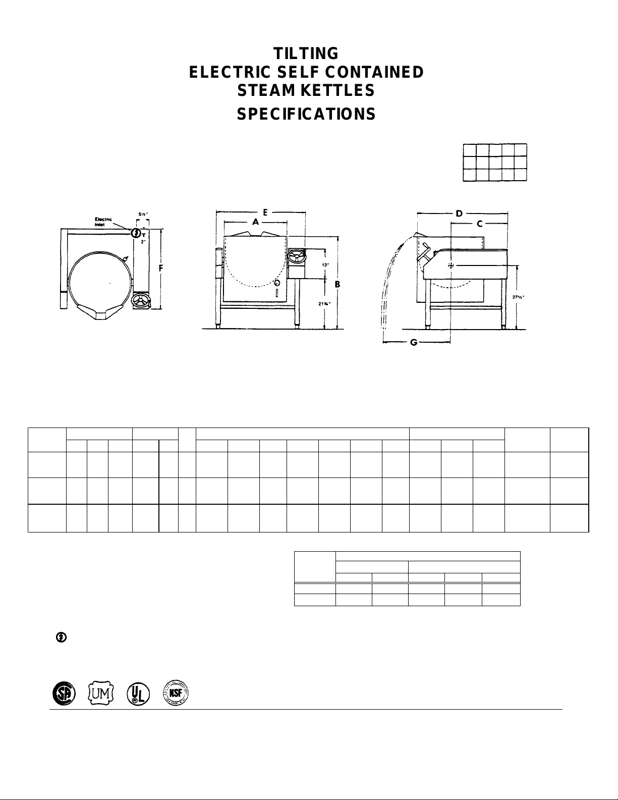
ELECTRIC SELF CONTAINED
STEAM KETTLES
SPECIFICATIONS
TOP VIEW FRONT VIEW SIDE VIEW
Not For Scale For Dimensional
Purposes Only
DIMENSIONS: ( ) = Millimeters
MODEL
KTLE-20 20 75 17 50 345 12
KTLE-40 40 150 34 50 345 24
KTLE-60 60 225 50 50 345 24
CAPACITY MAX DIMENSIONS CRATE SIZE
US. Liter Imp. Lb./in. KPa
(537)
(689)
(791)
UTILITY INFORMATION:
ELECTRIC — KTLE-20, KTLE-40, KTLE.60
STANDARD: 208/60/1 or 3 phase 240/60/1 or 3 phase
?
OPTIONAL: 480/60/3 (50 cycle - no charge)
Total maximum kilowatts: KTLE-20 - 12 KW; KTLE-40 - 24
KW; KTLE-60 - 24 KW.
ELECTRIC CONNECTION
APPROVALS:
A B C D E F G Width Depth Height
40"
(1016)
40"
(1016)
42"
(1067)
(502)
(591)
25.5"
(648)
31.25"
(1041)
32.25"
(794)
37"
38.25"
(940)
41"
42.25"
(1073)
TOTAL
K.W.
CONN.
24 116 100 67 58 29
31.25"
(819)
(972)
(794)
34.75"
(883)
(940)
SINGLE PHASE THREE PHASE
37"
23"
(584)
28"
(711)
32"
(813)
40"
(1016)
43"
(1092)
46"
(1168)
(914)
(1041)
(1168)
36"
41"
46"
50"
(1270)
50"
(1270)
52"
(1321)
CUBIC
VOLUME
42 cu. ft.
1.19cu. m.
51 cu. ft.
1.44 cu. m.
64 cu ft.
1.81 cu. m.
CRATED
WEIGHT
400 lbs.
181.4 kg.
530 lbs.
240.4 kg.
600 lbs.
272.2kg.
TILTING & STATIONARY ELECTRIC STEAM KETTLES
SECTION ONE — INSTALLATION
PAGE 1
Page 4
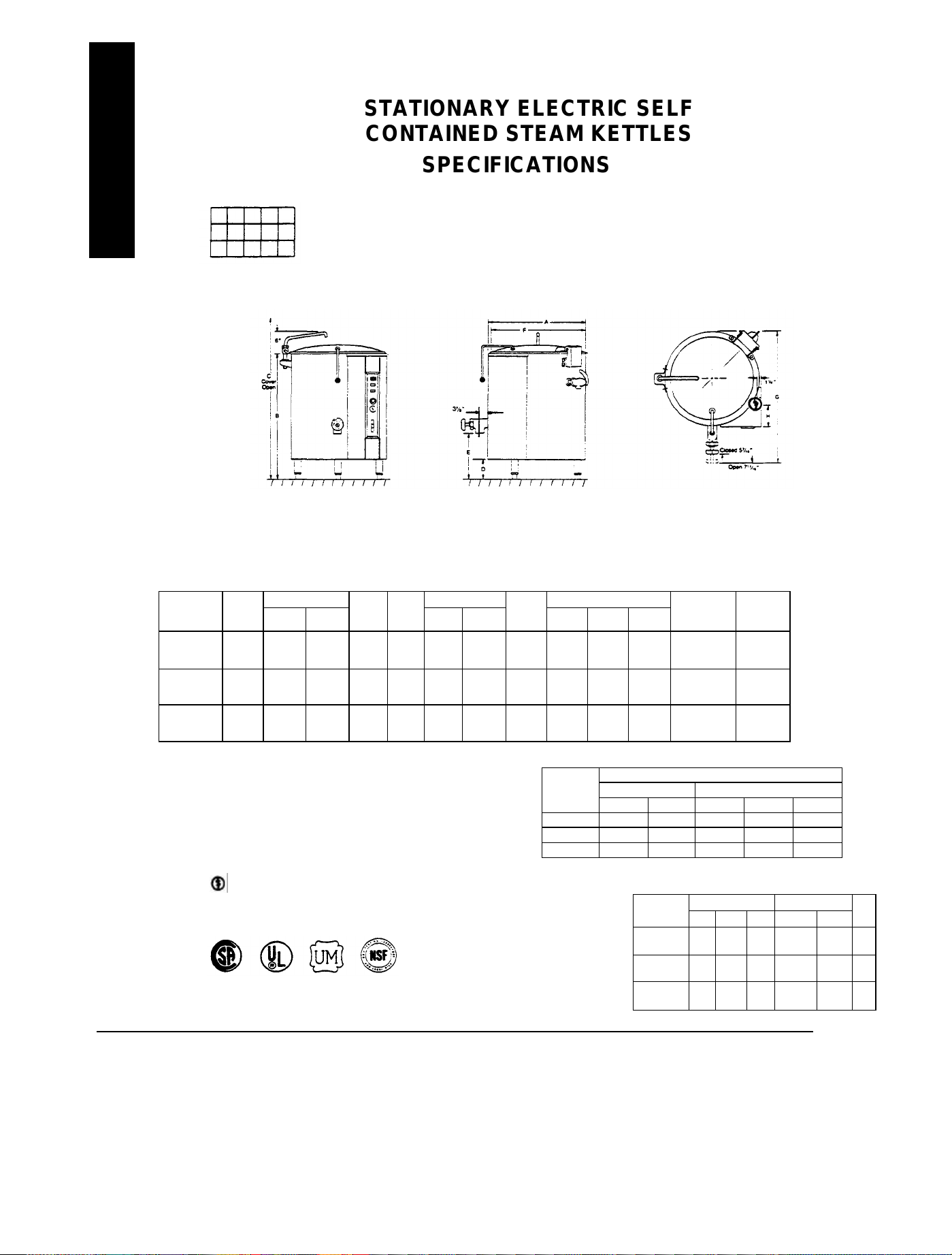
INSATALLATION
APPROVALS:
STATIONARY ELECTRIC SELF
CONTAINED STEAM KETTLES
SPECIFICATIONS
FRONT VIEW SIDE VIEW
Not For Scale For
Dimensional Purposes Only
DIMENSIONS: ( ) = Millimeters
33"
43"
Elec.
Conn.
H
6"
(152)
7"
(178)
8"
(203)
Width Depth Height
32"
(813)
(1016)
(1092)
TOTAL
K.W.
CONN.
32"
(813)
40"
40"
(1016)
43"
43"
(1092)
12 58 50 34 29 15
24 116 100 67 58 29
36 N.A. N.A. 100 87 44
40"
(1016)
48"
(1219)
58"
(1473)
TOTAL CONNECTED AMPS
SINGLE PHASE THREE PHASE
208V 240V 208V 240V 480V
MODEL
KSLE-20 20 75 17 50 345 12
MODEL
? KSLE-20
? KSLE-40
? KSLE-60
Width
A
22"
(559)
28"
(711)
32"
(813)
HEIGHT DEPTH CRATE SIZE
B C
37"
60.75"
(939)
(1543)
39"
68.25"
(991)
(1734)
42"
(1067)
75.75"
(1924)
D E
8.5"
(216)
6"
(152)
6"
(152)
16.5"
(419)
14.88"
(378)
15.13"
(384)
F G
21"
(533)
27"
(686)
31"
(787)
(838)
38.56"
(979)
(1092)
UTILITY INFORMATION:
ELECTRIC — KSLE-20, KSLE-40, KSLE-60
? STANDARD: 208/60/1 or 3 phase 240/60/1 or 3 phase (50 cycle
-no charge)
? OPTIONAL: 480/60/3 (50 cycle - no charge)
Total maximum kilowatts: KSLE-20 - 12 KW, KSLE-40 - 24
KW. KSLE-60 - 36 KW.
ELECTRIC CONNECTION
TOP VIEW
CUBIC
VOLUME
23.7 cu. ft.
.67 cu. m.
44.4 cu. ft.
1.25 cu. m.
62.1 cu. ft.
1.76 cu. m.
CAPACITY MAX.PRESS.
Liter
U.S.
CRATED
WEIGHT
360 lbs.
163.3 kg.
425 lbs.
192.8 kg.
500 lbs.
226.8 kg.
Imp. Lb./in.2 KPa
KW
TILTING & STATIONARY ELECTRIC STEAM KETTLES
SECTION ONE — INSTALLATION
PAGE 2
KSLE-40 40 150 34 50 345 24
KSLE-60 60 225 50 50 345 36
Litho in U.S.A.
4-88
Page 5
INSTALLATION
will relieve such vacuum. In case of unsatisfactory performance on any appliance, check with the exhaust fan in the
air openings, as well as for serviceability.
GENERAL:
THE UNIT WHEN INSTALLED MUST BE ELECTRICALLY GROUNDED AND COMPLY WITH LOCAL
CODES, OR IN THE ABSENCE OF LOCAL CODES, WITH THE NATIONAL ELECTRICAL CODE ANSI
NFPA 70-1984.
CANADIAN INSTALLATION MUST COMPLY WITH CSA STANDARD C22.1-CANADIAN ELECTRICAL
CODE PART 1.
EXHAUST FANS AND CANOPIES: Canopies are set over ranges, ovens, kettles, etc,, for ventilation purposes.
It is recommended that a canopy extend 6" past appliance and be located 6'6" from the floor. Filters should be
installed at an angle to 45° or more with the horizontal. This position prevents dripping of grease and facilitates
collecting the run-off grease in a drip pan, usually installed with the filter. A strong exhaust fan tends to create a
vacuum in the room and may interfere with performance. Makeup air openings approximately equal to the fan area
"OFF" position.
WALL EXHAUST FAN: The exhaust fan should be installed at least 2 feet above the vent opening at the top of
the unit.
CLEARANCES: Adequate clearance must be provided in aisle and at the side and back. Adequate clearances for
WARNING:
THESE PROCEDURES MUST BE FOLLOWED BY QUALIFIED PERSONNEL OR WARRANTY
CAN BE DECLARED VOID.
TO INSTALL:
1. Uncrate carefully. Report any hidden freight damage to the freight company immediately.
Set the unit in place. Be certain to maintain the following minimum clearances to combustible construction:
2.
3.
4. The pressure relief valve is located at the right rear of the unit. This area should be kept clear and should not be in an area
5. Check the pressure gauge on the front panel before operating. If the pressure gauge does not indicate 20 to 30 inches of
6.
SIDES — 2 Inches BACK — 2 Inches (at the flue box) FLOOR — 2 Inches
Allow enough clearance around the kettle for cleaning and maintenance.
To level the unit use a spirit level in all directions on the top of kettle (lid up).
A.
Units with legs — Adjust the bottom foot on each leg to overcome an uneven floor.
B.
Units with casters — Loosen the locking nuts, turn casters in or out as required and tighten locking nuts.
where operators will normally stand. The elbow on the relief valve should be turned toward the floor. A maximum 3 foot,
3/4" diameter pipe may be used to extend to the floor, but must not be piped directly to a drain. It must vent to the
atmosphere.
mercury column vacuum, see "Re-establishing Vacuum" section under SERVICE after completing installation
instructions.
This unit was shipped from the factory with a full charge of chemically pure water. This can be checked in two ways:
A.
Viewing water level through sight glass.
B.
When kettle is turned on, "Low Water" light will come on if water level is too low.
In either case, if the water level is low, the proper procedure is to remove the safety valve of the unit and fill with
chemically pure water to the right level looking thru sight glass. Replace safety valve securely.
In either case, the proper procedure would be to remove pressure relief valve and attach a 3/4" NPT elbow pointing
upward.
Using pure distilled water only, pour the water into the open end of the elbow (a funnel will be helpful). Water will enter
the kettle slowly, as air must escape through the same hole. Water should be added until the water level at the sight glass
is half way between the minimum and maximum levels.
TILTING & STATIONARY ELECTRIC STEAM KETTLES
SECTION ONE — INSTALLATION
PAGE 3
Page 6
INSTALLATION
Litho in U.S.A.
7. When sufficient water has been added, remove elbow and replace pressure relief valve. Be sure to seal
threads with a pipe joint compound suitable for steam at 50 psi.
8. The vacuum must now be re-established. See following section.
For reference, the total amount of distilled water contained in each unit is listed below:
RE-ESTABLISHING VACUUM:
With the kettle completely cold a vacuum of 25 to 30 inches mercury column (M.C.) should be maintained as
indicated by the pressure gauge on the front control panel. If at any time the vacuum is less than 25 inches M.C. the
vacuum should be re-established.
With the kettle empty, turn the thermostat knob to the highest temperature. When the pressure gauge reaches 20 psi,
turn thermostat off, open the pressure relief valve until manometer reads 1 psi, then sharply release it. This should
remove the air and any loss in performance should return.
Should the kettle fail to maintain a vacuum after repeated attempts to establish it, further checks should be made to
see if the pressure relief valve is leaking or if there are any leaks in the pressure relief valve piping, copper lines
going to the pressure switch, pressure gauge or thermostat fitting.
ELECTRICAL CONNECTIONS:
208/240 Single and Three Phase: I.
To connect to supply wires, route supply wire through hole in bottom of control compartment and connect to
contactor. Be sure to refer to wiring diagram and rating plate on each unit for proper connection, voltage and
amperage.
KTLE-20 1.5 gals. U.S. KSLE-20 7.2 gals. U.S.
KTLE-40 2.5 gals. U.S. KSLE-40 15.6 gals. U.S.
KTLE-60 3.0 gals. U.S. KSLE-60 22.8 gals. U.S.
480 Three Phase: II.
Units with this electrical rating are factory equipped with a transformer to control voltage to control circuit. Refer
to wiring diagram and rating plate on each unit for proper connection, voltage and amperage.
WATER CONNECTION:
On units equipped with an optional water fill valve connect a water line (minimum 1/4 ") to the valve with a 1/4" NPT
female fitting. Units with dual (hot & cold) valves must have the hot water line connected to the side with the hot water
valve (Red) and cold water valve (Blue). Plastic or rubber hose is not recommended, as it may melt against the hot
kettle side.
UNITS WITH CASTERS:
For a unit equipped with casters, the installation shall be made with a gas connector that complies with the standard
for connectors for movable gas appliances, ANSI Z 21.69-1979. Adequate means must be provided to limit the
movement of the unit, without depending on the connector and any quick disconnect device or its associated piping to
limit the unit's movement. If disconnection of this restraint is necessary to move the appliance for cleaning, etc.,
reconnect it when the appliance is moved to its originally installed position. A flexible conduit and adequate strain
relief must also be provided for the power supply connection.
If the unit is also equipped with an optional water fill valve, it too must be installed with a flexible water supply tube, a
quick disconnect, and strain relief.
WARNING:
DO NOT ALLOW ANY TAMPERING OR ADJUSTMENT OF ANY CONTROL OR WIRING. THE
UNIT IS FACTORY SET. ADJUSTMENT OF ANY INTERNAL COMPONENT, OTHER THAN THE
FIELD TERMINAL BLOCK, CAN VOID THE WARRANTY.
TILTING & STATIONARY ELECTRIC STEAM KETTLES
SECTION ONE — INSTALLATION
PAGE 4
4-88
Page 7
INSTALLATION
PERFORMANCE CHECK:
The following items should be checked before or within the first 30 days of operation by a qualified service technician.
1. Verify correct voltage, cycle and phase.
2. Check internal electrical connections.
3. Thermostat — cycle for operation check.
4. Check tilt mechanism if applicable.
5. Check hinge and lid assembly.
6. Draw-off valve — check operation if applicable.
7. Pressure gauge — check for operation.
8. Advise user on cleaning procedures.
TILTING & STATIONARY ELECTRIC STEAM KETTLES
SECTION ONE — INSTALLATION
PAGE 5
Page 8
TILTING AND STATIONARY
ELECTRIC SELF CONTAINED
STEAM KETTLES
LIMITED WARRANTY
Southbend warrants that the equipment, as supplied by the factory to the original purchasers, is free from defects in materials and workmanship.
Should any part thereof become defective as a result of normal use within the period and limits defined below, then at the option of Southbend such
parts will be repaired or replaced by Southbend or its Authorized Service Agency. This warranty is subject to the following conditions:
If upon inspection by Southbend or its Authorized Service Agency it is determined that this equipment has not been used in an appropriate manner,
has been modified, has not been properly maintained, or has been subject to misuse or misapplication, neglect, abuse, accident, damage during
transit or delivery, fire, flood, riot or Act of God, then this warranty shall be void.
Specifically excluded under this warranty are claims relating to installation; examples are improper utility connections and improper utilities supply.
Claims relating to normal care and maintenance are also excluded; examples are calibration of controls, and adjustments to pilots and burners.
Equipment failure caused by inadequate water quality is not covered under the warranty. WATER QUALITY must not exceed the following limits;
Total Dissolved Solids (TDS) - 60 PPM (Parts Per Million), Hardness - 2 Grains or 35 PPM, PH Factor - 7.0 to 7.5. Water pressure 30 PSI
minimum, 60 PSI Maximum. Boiler maintenance is the responsibility of the owner and is not covered by warranty.
This equipment is intended for commercial use only. Warranty is void if equipment is installed in other than commercial application.
Repairs under this warranty are to be performed only by a Southbend Authorized Service Agency. Southbend can not be responsible for charges
incurred from other than Authorized Southbend Agencies.
THIS WARRANTY MUST BE SHOWN TO AN AUTHORIZED SERVICE AGENCY WHEN REQUESTING IN-WARRANTY SERVICE WORK. THE
AUTHORIZED SERVICE AGENCY MAY AT HIS OPTION REQUIRE PROOF OF PURCHASE DATE.
This warranty does not cover services performed at overtime or premium labor rates nor does Southbend assume any liability for extended delays
in replacing or repairing any items in the equipment beyond the control of Southbend. "Southbend shall not be liable for consequential or special
damages of any nature that may arise in connection with such product or part." Should service be required at times which normally involve overtime
or premium labor rates, the owner shall be charged for the difference between normal service rates and such premium rates.
In all circumstances, a maximum of one hundred miles in travel and two and one half hours (2.5) travel time shall be allowable. In all cases the
closest Southbend Authorized Agency must be used.
The actual warranty time periods and exceptions are as follows:
This warranty only covers product shipped into the 48 Contiguous United States and Hawaii, one year labor, one year parts effective from the date
of original purchase. There will be no labor coverage for equipment located on any island not connected by roadway to the mainland.
Exceptions to standard warranty, effective within above limitations:
Glass Windows, Door Gaskets, Rubber Seals, Light Bulbs, Ceramic Bricks,
Sight Glasses, Cathodic Descalers or Anodes .................................................................................................................... 90 days material and labor.
Stainless Steel Fry Pot ................................................................................................. 4 years extended material warranty on fry pot only - No labor.
Stainless Steel Open Top Burners ............................................................................. 4 years extended material warranty on burners only - No labor.
Pressure Steam Boiler Shell ................................................................................. Prorated 4 years extended warranty on boiler shell only - No labor.
(Boiler shells which have not been properly maintained will not be covered by warranty.)
In all cases parts covered by a five year warranty will be shipped FOB the factory after the first year.
Our warranty on all replacement parts which are replaced in the field by our Authorized Service Agencies will be limited to three months on labor,
six months on materials (parts) effective from the date of installation. See LIMITED WARRANTY - REPLACEMENT PARTS for conditions and
limitations.
If the equipment has been changed, altered, modified, or repaired by other than a qualified service technician during or after the one year limited
warranty period, then the manufacturer shall not be liable for any damages to any person or to any property which may result from the use of the
equipment thereafter.
"THE FOREGOING WARRANTY IS IN LIEU OF ANY AND ALL OTHER WARRANTIES EXPRESSED OR IMPLIED INCLUDING ANY IMPLIED
WARRANTY OF MERCHANTABILITY OR FITNESS, AND CONSTITUTES THE ENTIRE LIABILITY OF SOUTHBEND. IN NO EVENT DOES THE
LIMITED WARRANTY EXTEND BEYOND THE DURATION OF ONE YEAR FROM THE EFFECTIVE DATE OF SAID WARRANTY."
SOUTHBEND - Effective February 1, 1990
TILTING & STATIONARY ELECTRIC STEAM KETTLES
SECTION TWO - USER'S GUIDE
PAGE 1
Page 9

OPERATION
tion must be followed
THEORY OF OPERATION:
One BTU (British Thermal Unit) is defined as the amount of heat required to raise one pound of water through one
degree Fahrenheit. Therefore, for one pound of water at room temperature, it takes 212° - 70° or 132 BTUs to bring
water to 212° F, the boiling point of water. However, in order to change this same pound of water at 212° F to steam at
212° F requires another 970 BTUs. This 970 BTUs is called the "heat of vaporization."
Upon contact with a cooler surface, this "heat of vaporization" is immediately given up.
Since a large amount of heat is given up at such a low temperature, 212° F, food is cooked quickly with relatively less
shrinkage and the foods valuable nutrients are retained.
In steam jacketed kettles, the steam is produced by the small amount of water between the jacket. This allows for fast,
uniform heating of the inner jacket and therefore, the product.
An additional advantage of this low temperature is that most foods won't stick to the sides. This transmits into reduced
labor costs since most foods do not require constant stirring.
DAILY OPERATION:
All equipment must be installed correctly to insure proper operation and reliable service. Installa
by a qualified technician.
Before you turn the unit on, be sure that you have: Power to the unit and any required waste drains plumbed in.
Set the thermostat to the desired temperature. The "Cooking" light will come on indicating that the heating elements
within the kettle are on. When the desired temperature is reached, the "Cooking" light will go out.
NOTE: IT IS ALWAYS A GOOD IDEA TO PREHEAT THE KETTLE EMPTY. DOING THIS WILL IMPROVE
PERFORMANCE.
Add product; thermostat will automatically cycle.
To turn the unit off, turn thermostat knob to "OFF" position.
Clean as required.
NOTE: Whenever kettle is tilted, power to the heating elements is turned off.
TILTING & STATIONARY ELECTRIC STEAM KETTLES
SECTION TWO — USER'S GUIDE
PAGE 2
Litho in
U.S.A
4-88
Page 10

OPERATION
4.
FRONT PANEL CONTROLS:
1. Power Switch — This switch turns the main power to the unit on and off. It must be turned on to heat the kettle. It should
be turned off when the kettle will not be in use for long periods.
2. (Red) Cooking Light — This light is on whenever the electric element is on.
3. (Amber) Low Water light — All kettles are supplied with sufficient distilled water in the pressurized jacket. If at any time
the water level falls below that required for proper operation, the kettle will not heat and this light will come on. See
"Adding Water" section of SERVICE instructions.
4. Thermostat — The thermostat selects the desired internal kettle operation temperature.
5. Pressure Gauge — The pressure gauge indicates the internal operating pressure of the kettle. When cold, the gauge should
indicate 25 to 30 inches mercury column vacuum. If it does not, refer to "Re-establishing Vacuum" section of SERVICE
instructions. Under normal operation with the kettle empty (thermostat set to 298° F) the pressure should be between 40
and 45 psi. When loaded the pressure may be considerably less.
6. Sight Glass — The sight glass indicates the minimum and maximum water level within the kettle. If water level falls
below minimum level more distilled water should be added. See "Adding Water" section of SERVICE instructions.
7. Pressure Relief Valve — The pressure relief valve is a safety device which prevents the internal kettles pressure from
ever exceeding 50 psi. It should never be tampered with.
COOKING HINTS
END USER TIPS:
It is a good idea to preheat the empty kettle EXCEPT when cooking milk and egg products.
When preparing foods containing vinegar or tomatoes, or which have a high salt content, clean the kettle immediately after
using to prevent pitting.
Do not use salt to clean the kettle. This will scratch the surface.
If using salt water to cook shellfish, be sure to rinse and wash the kettle thoroughly.
Grease the tilting mechanism on the KTLE about once a year with a non-toxic lubricant.
Bring milk and egg products slowly up to temperature in a cold kettle to prevent product from adhering to the sides.
Install a faucet or a hose to make the kettle easier to clean.
When planning actual cooking capacity, allow room at top for stirring without spilling.
When food is cooked it should be removed immediately to prevent overcooking and difficulty in cleaning.
If the pointer on the pressure gauge is between -25 and -30 and the kettle is at room temperature, the vacuum inside the kettle is
good.
ENERGY SAVING TIPS:
1.
Turn off when not in use.
2.
Set thermostat correctly.
3.
Use lid.
Maintain equipment.
TILTING & STATIONARY ELECTRIC STEAM KETTLES
SECTION TWO — USER'S GUIDE
PAGE 3
Page 11

MAINTENANCE
Litho in U.S.A.
Southbend equipment is sturdily constructed of the best quality materials and is designed to provide desirable service
when treated with ordinary care.
NOTE:
Your Southbend steam jacket kettle must be thoroughly cleaned at least once every day.
Certain foods containing salt, vinegar or tomato base additive may cause the inner surface of the kettle to
pit. The kettle should be thoroughly cleaned after each use when these types of food additives are used.
Before adding any food to your new Southbend kettle, it should be thoroughly cleaned to remove any trace of dirt or
oils left over from the manufacturing, storage or transportation of this unit.
TO CLEAN: Add about one gallon of warm water to the kettle. Using a mild detergent, thoroughly wash the inside
food contact surface. Drain and flush with clean water to remove any trace of detergent. Dry thoroughly and buff with
a dry cloth to bring out the luster of the stainless steel.
NOTE: Dismantle sanitary valve every day to clean the draw-off and the valve itself.
CAUTION: DO NOT USE VINEGAR OR ANY CORROSIVE CLEANER.
Following daily and periodic maintenance procedures will enhance long-life for your equipment. Climatic conditions —
salt air — may require more thorough and frequent cleaning or the life of the equipment could be adversely affected.
STAINLESS STEEL: To remove normal dirt, grease, or product residue from stainless steel use ordinary soap and
water (with or without detergent) applied with a sponge or cloth. Dry thoroughly with a clean cloth. Never use vinegar
or any corrosive cleaner.
To remove grease and food splatter or condensed vapors that have baked on the equipment, apply cleanser to a
damp cloth or sponge and rub cleanser on the metal in the direction of the polishing lines on the metal. Rubbing
cleanser as gently as possible in the direction of the polished lines will not mar the finish of the stainless steel. NEVER
RUB WITH A CIRCULAR MOTION. Soil and burnt deposits which do not respond to the above procedure can usually
be removed by rubbing the surface with SCOTCH-BRITE scouring pads or STAINLESS scouring pads. DO NOT USE
ORDINARY STEEL WOOL, as any particles left on the surface will rust and further spoil the appearance of the finish.
NEVER USE A WIRE BRUSH, STEEL SCOURING PADS (EXCEPT STAINLESS), SCRAPER, FILE OR OTHER
STEEL TOOLS. Surfaces which are marred collect dirt more rapidly and become more difficult to clean. Marring also
USER’S GUIDE
increases the possibility of corrosive attack. Refinishing may then be required.
TO REMOVE HEAT TINT: Darkened areas sometimes appear on stainless steel surfaces where the area has been
subjected to excessive heat. These darkened areas are caused by thickening of the protective surface of the stainless
steel and are not harmful. Heat tint can normally be removed by the foregoing, but tint which does not respond to this
procedure calls for a vigorous scouring in the direction of the polish lines, using SCOTCH-BRITE scouring pads or a
STAINLESS scouring pad in combination with a powdered cleanser. Heat tint action may be lessened by not applying
or by reducing heat to equipment during slack periods.
All food contact surfaces must be thoroughly drained and flushed prior to cooking in the kettle.
CONTROL PANEL: The textured control panel should be cleaned with warm water and mild soap. Never use an
abrasive cloth or steel wool. Never use cleaning solvents with a hydrocarbon base.
VENT SYSTEM: At least twice a year the unit venting system should be examined and cleaned.
END USER TIPS:
For easier cleaning add cold water to the kettle immediately after removing contents.
When preparing foods containing vinegar and/or tomatoes or those which have a high salt content, clean the kettle
immediately after using to prevent pitting.
Do not use salt to clean the kettle. This will scratch the surface.
If using salt water to cook shellfish, be sure to rinse and wash the kettle thoroughly.
Bring milk and egg products slowly to temperature in a cold kettle to prevent product adhering to the sides.
When planning actual cooking capacity, allow room at top for stirring without spilling.
When preparing puddings from a mix, place the powder in a cold kettle, add a small amount of the liquid, and stir to
form a thin paste. Turn on the kettle and add the remainder of the liquid. Continue as per recipe instructions.
When browning meat, bring the kettle up to temperature before adding the meat. This seals the juices in the meat.
TILTING & STATIONARY ELECTRIC STEAM KETTLES
SECTION TWO — USER'S GUIDE
PAGE 4
4-88
Page 12

TILTING AND STATIONARY
2.
2.
ELECTRIC SELF CONTAINED
STEAM KETTLES
SERVICE
ADJUSTMENTS
WARNING:
ADJUSTMENTS AND SERVICE WORK MAY BE PERFORMED ONLY BY A QUALIFIED
TECHNICIAN WHO IS EXPERIENCED IN, AND KNOWLEDGEABLE WITH, THE OPERATION
OF COMMERCIAL ELECTRIC COOKING EQUIPMENT HOWEVER, TO ASSURE YOUR
CONFIDENCE, CONTACT YOUR AUTHORIZED SERVICE AGENCY FOR RELIABLE SERVICE,
DEPENDABLE ADVICE OR OTHER ASSISTANCES, AND FOR GENUINE FACTORY PARTS.
All units are adjusted at the factory. In the case of problems at initial installation, check the supply voltage and compare with
information listed on the serial plate.
LOSS OF
VACUUM:
If the pointer on the pressure gauge is between -25 and -30 and the kettle is at room temperature,
the vacuum inside the kettle is good.
If the pointer on the pressure gauge is between -25 and 0 and the kettle is at room temperature,
the vacuum between the inner and outer jacket has been lost. This results in slow and inefficient
heat transfer, thereby, poor performance.
TO RE-ESTABLISH VACUUM: With the kettle empty, turn the thermostat knob to the highest temperature. When the
pressure gauge reaches 5 to 10 psi, open the pressure relief valve for 5 to 10 seconds, then sharply release it. This should
remove the air and any loss of performance should return.
Should the kettle fail to maintain a vacuum after repeated attempts to establish it, further checks should be made to see if the
pressure relief valve is leaking or if there are any leaks in the pressure relief valve piping, copper lines going to the pressure
switch, pressure gauge or thermostat fitting.
NOTE: Let unit cycle a few times to make sure that the thermostat is working properly.
THERMOSTAT:
The thermostat adjustment should not be changed until it is determined to be out of adjustment. Check the following before
changing the thermostat adjustment:
1. With kettle cold, the pressure on the pressure gauge should read 25 to 30 inches mercury column vacuum. If not, see "Re-
establishing Vacuum" section.
The pressure switch is not set too high or too low and causing the out of adjustment condition. A voltmeter should be used
by a properly trained serviceman to determine if the pressure switch or thermostat is actually cycling the elements. If the
pressure switch is found to be the problem, see "Pressure Switch" section.
Once the pressure switch is found to be operating properly, the thermostat should be set as follows:
1. Be certain kettle is empty.
Turn kettle on with thermostat set to 298° F.
3. Allow kettle to cycle two times.
TILTING & STATIONARY ELECTRIC STEAM KETTLES
SECTION THREE — SERVICE
PAGE 1
Page 13

ADJUSTMENTS
4. Using a voltmeter, determine if the elements are being cycled by the pressure switch or by the thermostat:
A. If the pressure switch is cycling the unit, the thermostat should be adjusted to a lower temperature. Turn the
5. Remove knob from dial shaft "B" in diagram below.
6. Increase kettle pressure by turning adjustment screw "A" counterclockwise. Decrease kettle pressure by turning adjustment
7. Turn adjustment screw slowly and allow kettle to cycle after each adjustment.
8. Replace thermostat knob.
PRESSURE SWITCH:
The pressure switch should not be adjusted until it is
determined to be the cause of an operating pressure
difficulty. See "Thermostat" section to determine if the
source of difficulty is the pressure switch or thermostat.
The major difficulties caused by pressure switch
misadjustment are:
thermostat adjustment lower until the thermostat is cycling the unit.
B. If the thermostat is cycling the unit, but the pressure reading on the gauge is too low, the thermostat adjustment may
be increased. Be certain, however, that it is not increased to the point where the pressure switch is cycling the unit.
screw clockwise.
1. Pressure relief valve opening, especially on preheat
from a cold start to 298° F (pressure switch set too
high).
2. Pressure in kettle is too low and elements are being shut down by the pressure switch (not thermostat).
The pressure switch is preset for proper operation from the factory. It is adjusted to the maximum pressure which will prevent the
pressure relief valve from opening. This setting will be slightly different on different kettle due to variations in the pressure relief
valves. During preheat to the maximum thermostat setting (298° F), from either a cold condition or a lower temperature setting,
the temperature may overshoot the thermostat setting and be shut down by the pressure switch.
This is normal, however, after the kettle has cycled several times (empty) the thermostat will begin cycling the unit.
TO ADJUST PRESSURE SWITCH:
1. With the kettle empty and completely cold, turn kettle on and set thermostat to maximum setting (298° F).
2. Pressure in kettle (read pressure gauge on front panel) should reach a maximum pressure of 40 to 45 psi and pressure relief
SERVICE
valve should not open. Kettle pressure may rise 3 or 4 psi even after elements shut down.
3. If relief valve does not open and kettle pressure is 40 psi or greater, pressure switch setting is satisfactory.
4. If relief valve opens, reduce setting on pressure switch, cool kettle completely by running cold water through it and repeat
this procedure.
5. If pressure in kettle is below or equal to 40 psi increase setting of pressure switch, cool kettle completely by running cold
water through it, and repeat this procedure.
6. To obtain access to the pressure switch the front panel must be removed. Remove the screws on either side of the panel. Be
sure to support the panel to avoid excessive strain on the wiring.
7. To increase the pressure switch setting, turn the white ribbed knob clockwise; to decrease turn it counterclockwise. Use the
center of the black ring as an indicator.
8. Replace the front panel when adjustment is complete.
TILTING & STATIONARY ELECTRIC STEAM KETTLES
SECTION THREE — SERVICE
PAGE 2
Litho in U.S.A.
4-88
Page 14

ADDING WATER:
SERVICE
1. Unit should be completely cold and off.
2. Lift handle of pressure relief valve to release vacuum in kettle (relief valve is at right rear of kettle).
3. Remove pressure relief valve and attach a 3/4" NPT elbow pointing upward.
4. Using pure distilled water only, pour the water into the open end of the elbow (a funnel will be helpful). Water will enter
the kettle slowly, as air must escape through the same hole. Water should be added until the water level at the sight glass
is half way between the minimum and maximum levels.
5. When sufficient water has been added, remove elbow and replace pressure relief valve. Be sure to seal threads with a
pipe joint compound suitable for steam at 50 psi.
6. The vacuum must now be re-established. See following section.
For reference, the total amount of distilled water contained in each unit is listed below:
RE-ESTABLISHING VACUUM:
With the kettle completely cold a vacuum of 25 to 30 inches mercury column (M.C.) should be maintained as indicated by the
pressure gauge on the front control panel. If at any time the vacuum is less than 20 inches M.C. the vacuum should be re-
established.
KTLE-20 1.5 gals. U.S. KSLE-20 7.2 gals. U.S.
KTLE-40 2.5 gals. U.S. KSLE-40 15.6 gals. U.S.
KTLE-60 3.0 gals. U.S.
KSLE-60 22.8 gals. U.S.
With the kettle empty, turn the thermostat knob to the highest temperature. When the pressure gauge reaches 5 to 10 psi, open
the pressure relief valve for 5 to 10 seconds, then sharply release it. This should remove the air and any loss in performance
should return.
Should the kettle fail to maintain a vacuum after repeated attempts to establish it, further checks should be made to see if the
pressure relief valve is leaking or if there are any leaks in the pressure relief valve piping, copper lines going to the pressure
switch, pressure gauge or thermostat fitting.
TILTING & STATIONARY ELECTRIC STEAM KETTLES
SECTION THREE — SERVICE
PAGE 3
Page 15

SERVICE
to occur. The kettle will have to
FIRST DISCONNECTING ALL POWER TO UNIT.
TROUBLE SHOOTING GUIDE:
SYMPTOM POSSIBLE CAUSE CORRECTION
No heat.
No power.
Low water. Fill with distilled water. See procedure on nameplate.
Is power to unit?
Is junction box on wall on?
Does voltage and phase match that of nameplate?
Is kettle in upright position (KTLE)?
Loose connections.
Low water light on.
Slow heating.
pressure relief valve.
Steam escapes
through pressure
relief valve.
NOTE:
Steam release over a long period of time will cause a low water condition
be recharged with distilled water.
NO REPAIRS INVOLVING THE ELECTRICAL SYSTEM SHOULD BE UNDERTAKEN WITHOUT
Loss of vacuum in steam jacket. Cook kettle to run temp. If vacuum is between 0 & 25, re-establish
Defective thermostat. Check if contact opens freely.
Wrong pressure switch setting. Adjust to 40 psi. Replace switch if found defective. Steam escapes from
Thermostat setting too high. Adjust thermostat. Replace if found defective.
Foreign matter under seat.
Check water level in sight glass. If low, fill with distilled water.
See procedure on nameplate.
vacuum.
Check nameplate for correct voltage and phase. Wrong voltage or phase.
Check amperage.
With kettle heated to 5 to 10 psi, open valve and release sharply
several times. If this fails to dislodge material, replace the valve.
NOTE: Under no circumstances should an attempt be made to
remove seat.
TILTING & STATIONARY ELECTRIC STEAM KETTLES
SECTION THREE — SERVICE
PAGE 4
Litho in U.S.A.
4-88
Page 16

SERVICE
TILTING & STATIONARY ELECTRIC STEAM KETTLES
SECTION THREE — SERVICE
PAGE 5
Page 17

SERVICE
Litho in U.S.A.
SERVICE
TILTING & STATIONARY ELECTRIC STEAM KETTLES
SECTION THREE — SERVICE
PAGE 6
4-88
Page 18

SERVICE
TILTING & STATIONARY ELECTRIC STEAM KETTLES
SECTION THREE — SERVICE
PAGE 7
Page 19

SERVICE
SERVICE
TILTING & STATIONARY ELECTRIC STEAM KETTLES
SECTION THREE — SERVICE
PAGE 8
Litho in U.S.A.
4-88
Page 20

SERVICE
TILTING & STATIONARY ELECTRIC STEAM KETTLES
SECTION THREE — SERVICE
PAGE 9
Page 21

TILTING AND STATIONARY
necessary, please consult Southb
end Parts Department for assistance.
ELECTRIC SELF CONTAINED
STEAM KETTLES
PARTS
WARNING:
INSTALLATION OF OTHER THAN GENUINE SOUTHBEND PARTS WILL VOID THE
WARRANTY ON THIS EQUIPMENT.
The serial plate is located:
ON TILTING UNITS — on the rear of the console in the bottom right-hand corner;
ON STATIONARY UNITS - on the lower right side.
Replacement parts may be ordered either through a Southbend Authorized Parts Distributor or a Southbend
Authorized Service Agency.
When ordering parts please supply the Model Number, Serial Number, Part Number, Description, plus Finish and
Electrical Characteristics, as applicable.
For parts not listed consult a Southbend Authorized Parts Distributor or Southbend Authorized Service Agency. If
TILTING MODEL
— Please refer to Parts List Charts for proper Key Number identification. —
TILTING & STATIONARY ELECTRIC STEAM KETTLES
SECTION FOUR — PARTS
PAGE 1
Page 22

PARTS
TILTING MODEL
— Please refer to Parts List Charts for proper Key Number identification.
STATIONARY MODEL
— Please refer to Parts List Charts for proper Key Number identification.
TILTING & STATIONARY ELECTRIC STEAM KETTLES
SECTION FOUR — PARTS
PAGE 2
Litho in U.S.A.
4-88
Page 23

MODEL: KTLE (Tilting Models)
PORCELAIN INSULATOR
- 6KW.
240V
(6600656)
PARTS
USAGE
208/1
208/3
208/1
208/3
208/1
208/3
240/1
240/3
240/1
KEY
PART NO.
NO.
9 PE-123 RED PILOT LIGHT - 250V RECT. (1161515) 1 1 1 1 1 1 1 1 1 1 1 1 1 1 1
8 PE-124 AMBER PILOT LIGHT - 250V RECT. (1167450) 1 1 1 1 1 1 1 1 1 1 1 1 1 1 1
4 1166562 THERMOSTAT 1 1 1 1 1 1 1 1 1 1 1 1 1 1 1
5 PE-126 THERMOSTAT KNOB (1167451) 1 1 1 1 1 1 1 1 1 1 1 1 1 1 1
10 PP-694 CHROME SAFETY VALVE (1167456) 1 1 1 1 1 1 1 1 1 1 1 1 1 1 1
2 PE-120 LOW WATER CONTROL (1167447) 1 1 1 1 1 1 1 1 1 1 1 1 1 1 1
PE-121 PROBE FOR LOW WATER (1167448) 1 1 1 1 1 1 1 1 1 1 1 1 1 1 1
6 PP-637 PRESSURE/VACUUM GAUGE (6600280) 1 1 1 1 1 1 1 1 1 1 1 1 1 1 1
7 PM-097 SIGHT GLASS (1166460) 1 1 1 1 1 1 1 1 1 1 1 1 1 1 1
PP-688 PRESSURE CONTROL SWITCH (1167455) 1 1 1 1 1 1 1 1 1 1 1 1 1 1 1
PM-012 BULLET FOOT -2" (1166490) 4 4 4 4 4 4 4 4 4 4 4 4 4 4 4
PM-023 HANDLE KNOB (6600358) 1 1 1 1 1 1 1 1 1 1 1 1 1 1 1
3 PE-005 CONTACTOR - 75A. 208/240 (6600052) 1
3 PE-006 CONTACTOR - 40A. 208/240 (6600054) - 1 - - - 1 - 1 - - 1 1 1 1 1
1 PE-023 TERMINAL BLOCK (1167335) 3 3 - 3 - 3 3 3 - 3 - 3 3 3 3
1 PE-024 TERMINAL BLOCK END (1167446) 1 1 - 1 - 1 1 1 - 1 - 1 1 1 1
PE-169
1-0189-2 HEATING ELEMENT - 4KW. 240V (6600178) - - - - - - 3 3 6 6 6 6 - - -
1-0189-5 HEATING ELEMENT - 4KW. 208V (1167458) 3 3 6 6 6 6 - - - - - - - - -
1-0189-7
1-0189-9
1-0189-10
TERMINAL BLOCK HIGH 150 AMP. 600V
HEATING ELEMENT - IMMERSION
PORCELAIN INSULATOR - 4KW, 480V (6600654)
HEATING ELEMENT - IMMERSION
PORCELAIN INSULATOR - 6KW, 208V (6600655)
HEATING ELEMENT - IMMERSION
DESCRIPTION
20
40
GAL.
GAL.
2 1 2 1 1 - 2 1 1 1 - - -
- - 1 - 1 - - - 1 - 1 - - - -
- - - - - - - - - - - - 3 6 6
- - - - - - - - - - - - - - -
- - - - - - - - - - - - - - -
GO
GAL.
20
GAL.
240/3
40
GAL.
240/1
60
GAL.
480V, 3 PH
240/3
20 G40 G60
GA
PE-152
PM-100 CLEANING BRUSH FOR 2" DRAWOFF (6600658) 1 1 1 1 1 1 1 1 1 1 1 1 1 1 1
1-0188-2 STRAINER FOR 2" DRAWOFF 1 1 1 1 1 1 1 1 1 1 1 1 1 1 1
PP-641 DRAWOFF VALVE - 2" 1 1 1 1 1 1 1 1 1 1 1 1 1 1 1
HAMMOND TRANSFORMER
- 240-480/120-240V (6600657)
- - - - - - - - - - - - 1 1 1
TILTING & STATIONARY ELECTRIC STEAM KETTLES
SECTION FOUR — PARTS
PAGE 3
Page 24

PARTS
MODEL: KSLE (Stationary Models)
KEY
PART NO. DESCRIPTION
NO.
USAGE
480V, 3 PH
20 GAL. 40 GAL.
PE-123 RED PILOT LIGHT - 250V RECT. (1161515) 1 1 1 1 1 1 1 1 1 1 1 1 1
PE-124 AMBER PILOT LIGHT - 250V RECT. (1167450) 1 1 1 1 1 1 1 1 1 1 1 1 1
2 1166562 THERMOSTAT 1 1 1 1 1 1 1 1 1 1 1 1 1
3 PE-126 THERMOSTAT KNOB (1167451) 1 1 1 1 1 1 1 1 1 1 1 1 1
12 PP-694 CHROME SAFETY VALVE (50 PSI) (1167456) 1 1 1 1 1 1 1 1 1 1 1 1 1
8 PE-120 LOW WATER CUT OFF (1167447) 1 1 1 1 1 1 1 1 1 1 1 1 1
9 PE-149 PROBE FOR LOW WATER (1166452) 1 1 1 1 1 1 1 1 1 1 1 1 1
5 PP-637 PRESSURE/VACUUM GAUGE (6600280) 1 1 1 1 1 1 1 1 1 1 1 1 1
7 PM-097 SIGHT GLASS ASSY. (1166460) 1 1 1 1 1 1 1 1 1 1 1 1 1
4 PP-688
PM-012 BULLET FOOT - 2" (6600363) 3 3 3 3 3 3 3 3 3 3 3 3 3
PM-023 HANDLE KNOB (6600358. 1166497) 1 1 1 1 1 1 1 1 1 1 1 1 1
1 PE-005 CONTACTOR - 75A. 208/240 (6600052) 1 - 2 1 2 1 - 1 1 2 - - 1 PE-006 CONTACTOR - 40A, 208/240 (6600054) - 1 - - - - 1 1 - - 1 1 1
10 PE-023 TERMINAL BLOCK (1167445) 3 3 - 3 - 3 3 - 3 - 3 3 3
10 PE-024 TERMINAL BLOCK END (1167446) 1 1 - 1 - 1 1 - 1 - 1 1 1
PE-169
6 1-0189-2 HEATING ELEMENT - 4KW. 240V (6600178) - - - - - 3 3 6 6 - - - -
6 1-0189-5
6 1-0189-7
6 1-0189-9
6 1-0189-10
PE-152
PM-100 CLEANING BRUSH FOR 2" DRAWOFF (6600658) 1 1 1 1 1 1 1 1 1 1 1 1 1
1-0188-2 STRAINER FOR 2" DRAWOFF (1167528) 1 1 1 1 1 1 1 1 1 1 1 1 1
11 PP-641 DRAWOFF VALVE - 2" (6600277) 1 1 1 1 1 1 1 1 1 1 1 1 1
PRESSURE CONTROL SWITCH (1167455.
TERMINAL BLOCK HIGH 150 AMP, 600V
HEATING ELEMENT - IMMERSION
PORCELAIN INSULATOR - 4KW. 208V (1167458)
HEATING ELEMENT - IMMERSION
PORCELAIN INSULATOR - 4KW, 480V (6600654)
HEATING ELEMENT - IMMERSION
PORCELAIN INSULATOR - 6KW. 208V (6600655)
HEATING ELEMENT - IMMERSION
PORCELAIN INSULATOR - 6KW. 240V (6600656)
HAMMOND TRANSFORMER
- 240-480/120-240V (6600657)
1 1 1 1 1 1 1 1 1 1 1 1 1
- - 1 - 1 - - 1 - 1 - - -
3 3 6 6 - - - - - - - - -
- - - - - - - - - - 3 6 6
- - - - 6 - - - - - - - -
- - - - - - - - - 6 - - -
- - - - - - - - - - 1 1 1
60
20 GAL 40 GAL.
GAL
60
GAL.
20
GAL
40
GAL
TILTING & STATIONARY ELECTRIC STEAM KETTLES
SECTION FOUR — PARTS
PAGE 4
60
GAL
Litho in U.S.A.
4-88
Page 25

southbend
A MIDDLEBY COMPANY
1100 Old Honeycutt Road
Fuquay-Varina. NC 27526
(919) 552-9161
FAX (919) 552-9798
(800) 348-2558
Convection ovens
Cook & hold convection ovens
Bake 6, roast ovens
Pizza ovens
Ranges
Fryers
Special S. custom equipment
Convection steamers
Steam kettles
Tilting braising pans
Cooker/mixer kettles
Floor model broilers
Under fired broilers
Salamander broilers
Cheese melters
Page 26

TILTING AND STATIONARY
A
PART NUMBER A44
-
00008
ELECTRIC SELF CONTAINED
STEAM KETTLES
A product with the Southbend name incorporates the best in durability and low
maintenance. We all recognize however, that replacement parts and occasional
professional service may be necessary to extend the useful life of this unit. When
service is needed, contact a Southbend Authorized Service Agency, or your dealer. To
avoid confusion, always refer to the model number, serial number, and type of your
unit.
MIDDLEBY COMPANY
southbend
Fuquay-Vanna. NC 27526
(919) 552-9161
1100 Old Honeycutt Road
FAX (919) 552-9798 (800)
348-2558
Litho in USA
 Loading...