

Page 1
IMPORTANT
MODELS: KECT
-
06
FOR FUTURE REFERENCE
Please complete this information
and retain this manual for the life
o( the equipment.
MODEL #
SERIAL #
DATE PURCHASED
OPERATOR'S MANUAL
INSTALLATION
OPERATION AND MAINTENANCE INSTRUCTIONS
SELF-GENERATING STEAM JACKETED COUNTER TILTING KETTLE
KECT-10
KECT-12.
1100 Old Honeycutt Road • Fuquay-Varina, NC 27526• (919)552-9161• FAX (919) 552-9798 •(800) 348-2558
Middleby Corp. Service Hot Line (800)238-8444 (after hours)
Page 2
INSTALLATION AND OPERATION
PAGE
It is recommended that this manual be read thoroughly and that all
instructions be followed carefully. This manual should be retained
for future reference.
DO NOT ATTEMPT TO OPERATE THIS UNIT IN THE EVENT OF A
POWER FAILURE
ADEQUATE CLEARANCES MUST BE MAINTAINED FOR SAFE AND
PROPER OPERATION
INDEX
DESCRIPTION
INDEX .............................................................................. 1
INSTALLATION AND SERVICE CONNECTIONS ............................................... 2
INSTALLATION INSTRUCTIONS .......................................................... 3
INTRODUCTION ....................................................................... 4
OPERATION INSTRUCTIONS ............................................................. 5
CLEANING INSTRUCTION ............................................................... 6
TROOBLESHOOTING .................................................................... 7
Page 3
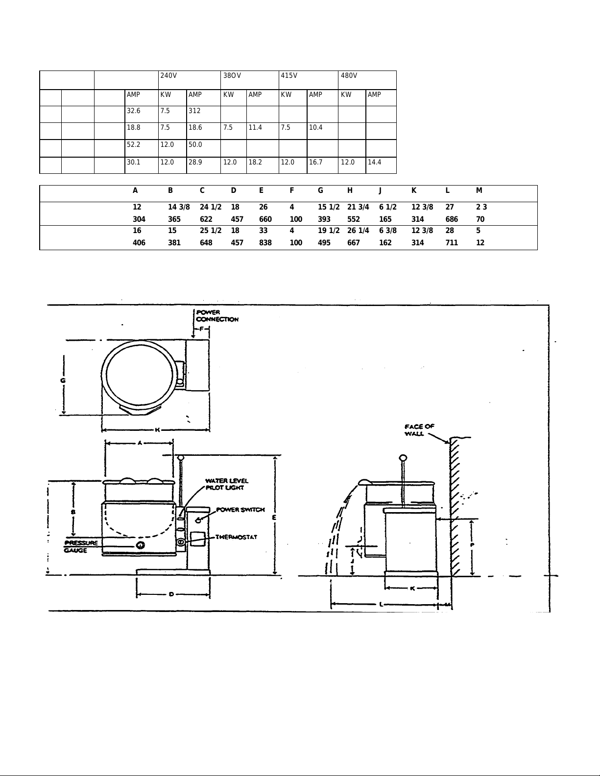
208V 230V 240V 38OV 415V 480V
KW AMP KW AMP KW AMP KW AMP KW AMP KW AMP
36.0 7.5 32.6 7.5 312
7.5 20.8 7.5 18.8 7.5 18.6 7.5 11.4 7.5 10.4
12.0 57.6 12.0 52.2 12.0 50.0
12.0 33.3 12.0 30.1 12.0 28.9 12.0 18.2 12.0 16.7 12.0 14.4
Capacity
U.S. gal inches 12 14 3/8 24 1/2 18 26 4 15 1/2 21 3/4 6 1/2 12 3/8 27 2 3/4 12 3/8
9 liter mm 304 365 622 457 660 100 393 552 165 314 686 70 314
U.S. gal inches 16 15 25 1/2 18 33 4 19 1/2 26 1/4 6 3/8 12 3/8 28 5 14 3/4
8 liter mm 406 381 648 457 838 100 495 667 162 314 711 127 374
A B C D E F G H J K L M P
As a continued product improvement is a policy of SouthBend, specifications are subject to change without notice.
Page 4

[NSTALLATION
Installation
Position kettle on counter allowing sufficient rear clearance from wall to tilt freely and completely
without obstruction.
Mark four corner locations of kettle base/ as shown below.
Remove kettle from counter and locate position of 4 holes as per above drawing. Drill four 7/6" diameter
holes.
Apply a continuous bead of Silastic or other equivalent sealant along the complete perimeter
edge of the kettle base.
Use 5/16-18 x 1/2" Hex Cap Screws with suitable flat washers to bolt down.
Wipe off excess sealant.
A Control Box with power supply equivalent to Electrical Rating of kettle should be located
conveniently nearby.
A waterproof electrical connection for power supply to console housing must be provided.
Ground kettle to terminal provided inside console housing.
Turn power ON and check for proper operation.
Page 5

INTRODUCTION
Description
Models KECT-06 gallon capacity and KECT-10 (10 gallon capacity) are electrically powered, selfcontained, counter-top, tilting Kettles.
This model has a jacket of double-wall construction forming a reservoir around the lover two-thirds of the
kettle. The reservoir is charged with water and anti-freeze solution. Kettles equipped with a removable
electric heating element and controls, including a low water cutoff device for protection of the heating
element. Both models are of identical construction, except kettle size-and element, heating capacity.
c Functioning •
Self-contained kettles operate by generating steam in the kettle reservoir. The sequence of operation is as
follows:
Operator flips the power switch to the ON position and sets the temperature control dial at the desired
setting from 1 to 10 (90 degrees fahrenheit to 300 degrees fahrenheit, 32 agrees celsius to 149 degrees
celsius, jacket temperature).
Control circuit is normally completed to the temperature controller if the following conditions exist:
Water level in the kettle reservoir is adequate to prevent circuit interruption by the low water cutoff
device. An activated cutoff is indicated by the amber low water light turning on, and the heating element
shut off.
Kettle is in vertical position with circuit completed through the tilt interlock switch (Micro switch).
Thermostatic control contacts close to energize contactor coils.
Power is supplied to the elements through closed power contactors.
As the temperature of water rises in the kettle reservoir, increase in steam pressure is indicated on the
pressure gauge.
When the temperature of steam in the reservoir reaches the setting shown on the temperature control
dial, the temperature, controller opens to break the contacts and shut
of the heating element. On/off cycles will occur as required to maintain temperature control.
Page 6

OPERATION INSTRUCTIONS
Ensure that the external electrical shut-off to kettle is on.
Check pressure gauge for correct cold kettle reading. Reading should be 25-30 in. Hg (84-100 k/Pa) of
vacuum. If reading is not low enough follow VENTING procedure prior to using kettle.
Place power switch in ON position.
Preheat kettle by placing thermostat knob at '10' arid wait until TEMPERATURE light goes off.
NOTE: Preheating should not be used when cooking milk
and egg food products, which adhere to hot cooking
surfaces. These foods should be placed into kettle
before heating is begun.
Add food to be cooked into kettle.
Place thermostat knob at required temperature setting from 1° to 10° coinciding with a temperature range
from roughly 90 degrees Fahrenheit to 300 degrees Fahrenheit (32 degrees Celsius to 149 degrees
Celsius in the reservoir. Approximate cooking temperatures with water at various thermostat settings are
as follows:
THERMOSTAT SETTING
APPROXIMATE TEMPERATURE (WATER)
F C
4
5
6
7
8
9
10
90 Degrees
125 Degrees 52 Celsius
160 Degrees 71 Celsius
195 Degrees 91 Celsius
231 Degrees 110 Celsius
273 Degrees
300 Degrees 149 Celsius
32 Celsius
134 Celsius
When cooking is finished set thermostat knob and power switch to OFF position.
Pour finished product from kettle using tilt handle. Be careful to avoid splashing.
Add water to kettle for cleaning purposes. Wash kettle thoroughly. See CLEANING procedure.
Page 7

Cleaning Instructions
The kettle interior and exterior should be thoroughly washed after each use in preparation of a different food.
1. Add water and mild detergent to the kettle immediately after use.
2. Scrub kettle interior with a nylon brush.
NOTE: Never scrape the inside of the kettle with metal tools, steel scouring pads, or abrasive cleaners.
Scratches will result which will spoil the kettle's general appearance and make it harder to clean and
maintain a sanitary condition.
3. Loosen food which is stuck to kettle by allowing it to soak:
at a low temperature setting.
4. Rinse with clear water and dry.
WARNING: Do not hose down until under any condition. Failure to comply will void warranty.
5. Wipe down exterior, rinse and dry.
WARNING
It is NOT RECOMMENDED to use cleaning agents that are corrosive.
Use of cleaning agents that contain chloride, acids or salts are corrosive and may cause pitting and corrosion
when used over a period of time; this will reduce the life of the appliance.
Should pitting or corrosion occur this is not covered by warranty.
Follow the recommended cleaning instructions. Use mild detergent, warm water and rinse thoroughly.
Page 8

TROUBLESHOOTING
SELF-GENERATING STEAM JACKETED
TILTING COUNTER TOP KETTLE
GENERAL MAINTENANCE
Some general maintenance is required other than adhering to the Cleaning Procedure instructions.
WATER LEVEL
Upper water level must be maintained within the jacket for the kettle to operate. Depletion of water may
occur from excessive opening of, or leakage through the safety relief valve.
water is below required operating level, either initially at startup or during use, the kettle will automatically
shut off, use to operate and the LOW WATER signal light will come on.
In order for the kettle to operate, the following procedure must be followed:
Trip the safety relief valve lever to relieve all pressure from the kettle jacket.
At exterior rear of kettle jacket remove nut from Air Vent.
Insert funnel into Air Vent opening and slowly add the indicated amount of clean water for:
KECT-6 Add 50 oz. (1.5 Litres)
KECT-10 Add 100 oz. (3 Litres)
Replace Air Vent nut.
Follow Air Venting Instructions below.
Continue normal Operating Procedure of kettle.
Page 9

Cleaning Instruction
Check vacuum/pressure gauge when kettle is cold. Gauge should be the vacuum zone between 25-30 in.
Hg (84-100k/Pa). If not, air present, which must be vented (removed) for proper heating. Use following
procedures to vent air.
Place power switch in ON position; kettle empty.
Set temperature control thermostat to '10'. Heat kettle until heat indicator light goes off.
Using a 7/16" wrench, open bleed vent one full turn for 10 seconds and close.
Cool kettle. Check for proper vacuum of 25-30 in. Hg (84-100k/Pa). If reading is not low enough, repeat
entire procedure, steps 1-3.
 Loading...