

Page 1
PARTS MANUAL
G & SL-Series
E
LECTRIC
C
ONVECTION OVENS
SLEB/10CCH
SL-Series Models
SLEB/10SC
SLEB/20CCH
SLEB/20SC
SLES/10CCH
SLES/10SC
SLES/20CCH
SLES/20SC
EB/10CCH
G-Series Models
EB/10SC
EB/20CCH
EB/20SC
ES/10CCH
ES/10SC
ES/20CCH
ES/20SC
Model ES/10SC Model ES/20SC
1100 Old Honeycutt Road, Fuquay-Varina, NC 27526
www.southbendnc.com
Copyright © 2013 by Southbend. All rights reserved. Published in the United States of America.
M
ANUAL
1198301
FULL SIZE
ELECTRIC CONVECTION OVENS
Page 2
I
INFOR MATION
NFORMATION
Replacement parts may be ordered either through a Southbend Authorized Parts Distributor or a
Southbend Authorized Service Agency. It is recommended to verify part numbers with a Southbend
Authorized Parts Supplier or the Southbend Parts/Service Dept. prior to ordering parts.
F
ULL SIZE
E
LECTRIC CONVECTION OVENS
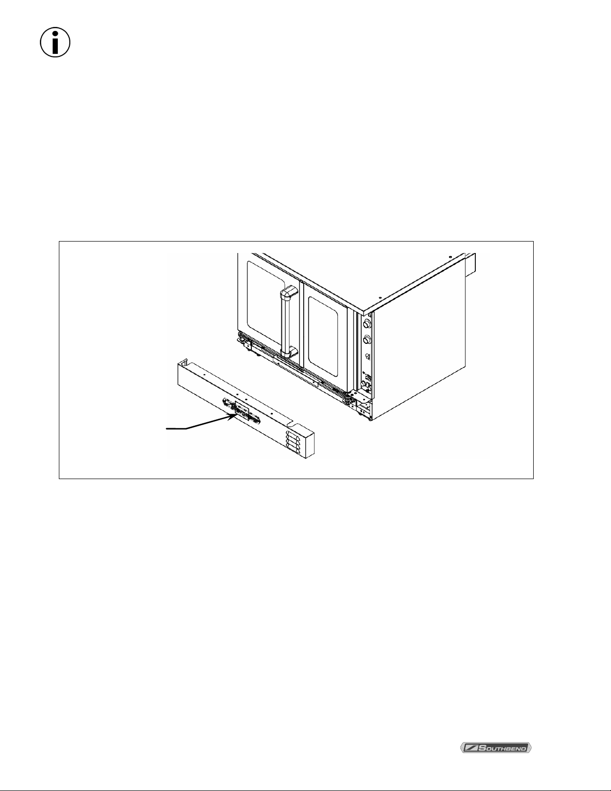
When ordering parts, you will need to supply the Model Number, Serial Number,
Part Number, Description, Finish, and Electrical Characteristics as applicable to
the unit.
The serial plate is located on the interior side of the lower front panel, as shown below.
Serial plate
(inside panel)
P
AGE
2 P
ARTS MANUAL
1198301
Page 3
FULL SIZE ELECTRIC CONVECTION OVENS INFORMATION
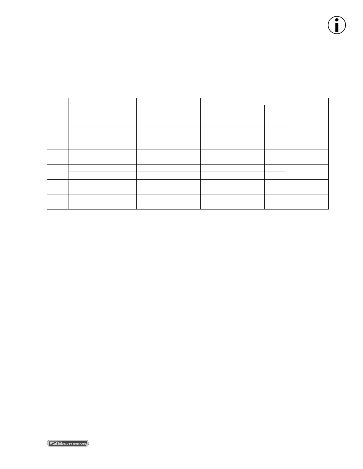
SPECIFICATIONS
ELECTRICITY SUPPLY
The following table lists the electricity supply requirements PER OVEN (double for dual-oven models).
Supply
Voltage
480
415
380
240
220
(50Hz)
208
Oven Component
Heating Elements 11.00 3.67 3.67 3.67 13.2 13.2 13.2 22.9
Motor & Controls 0.90 0.00 0.00 0.00 2.2 0.0 2.2 2.2
Heating Elements 11.00 3.67 3.67 3.67 15.3 15.3 15.3 45.9
Motor & Controls 0.90 0.00 L3-N 0.90 0.0 0.0 3.8 3.8
Heating Elements 11.00 3.67 3.67 3.67 16.7 16.7 16.7 28.9
Motor & Controls 0.90 0.00 L3-N 0.90 0.0 0.0 4.1 4.1
Heating Elements 11.00 3.67 3.67 3.67 26.4 26.4 26.4 45.8
Motor & Controls 0.90 0.00 0.00 0.90 3.8 0.0 3.8 3.8
Heating Elements 9.25 3.10 3.10 3.10 24.2 24.2 24.2 42.0
Motor & Controls 0.90 0.00 0.00 0.90 4.1 0.0 4.1 4.1
Heating Elements 11.00 3.67 3.67 3.67 30.5 30.5 30.5 52.9
Motor & Controls 0.90 0.00 0.00 0.90 4.3 0.0 4.3 4.3
Total
3-Phase Loading (kW/phase)
kW
L1-L2 L2-L3 L1-L3 L1 L2 L3
Nominal Amperes per Line-Wire
3-Phase
1-Phase
Total
Minimum Supply
Wire (AWG) Size
3-Phase 1-Phase
12 10
12 6
12 8
8 6
8 6
8 4
An electrical diagram is located on the side of the control panel assembly (see drawing on page 5).
Electrical diagrams can also be found in the Operator's manual.
The appliance, when serviced, must be electrically grounded in accordance with local codes, or in the
absence of local codes, with the National Electrical Code, ANSI/NFPA 70, or the Canadian Electrical Code,
CSA C22.2, as applicable.
Use 167°F (75°C) wire for all supply lines.
Ovens are shipped wired for either single-phase or three-phase operation, depending on which was
specified on the factory order. If necessary an oven can be field-converted. Reference Operator's Manual
for wiring connection information.
INFOR MATION
The electrical connections are made directly to the terminals of the heating-element contactor, which is
located inside the control-panel compartment on the right side of the oven. A circular opening sized for a
strain-relief fitting is located on the back of the oven near the right side (on right as seen from the front of
the oven, see illustration on page 4). Models with two stacked ovens have a separate electrical connection
for each oven.
PARTS MANUAL 1198301 PAGE 3
Page 4
I
INFOR MATION
NFORMATION
F
ULL SIZE ELECTRIC CONVECTION OVENS
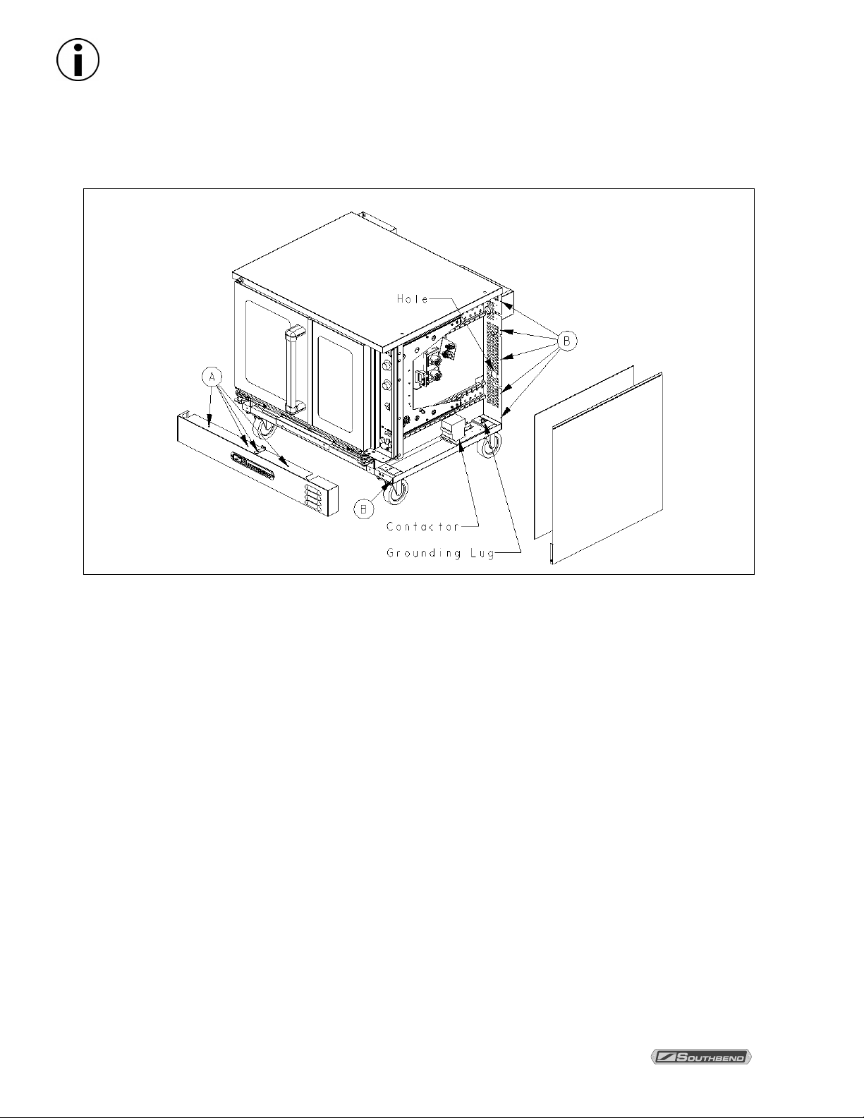
Connecting Electrical Supply
The following drawing shows the locations of items for the 208-240V electrical supply. Reference Owners
manual for other voltage options.
E
LECTRICAL CONNECTION ACCESS
1. CHECK THAT THE POWER SUPPLY CIRCUIT BREAKER IS OPEN.
2. Locate and remove the four screws that secure the lower front panel (items “A” in the drawing above).
Lift up the panel and pull it forward to remove it, then set it aside.
3. Locate and remove the front screw (item “B” in the drawing above), that secures the lower front corner
of the side panel.
4. Locate and remove the five rear screws that secure the back edge of the side panel to the oven (items
“B” in the drawing above). Remove the side panel and insulation and set them aside.
5. Route the supply wires and the grounding wire through the hole on the back of the oven. Use a strainrelief fitting.
6. Attach each supply wire to the appropriate terminal of the contactor (according to wiring diagram).
7. Insert the ground wire into the grounding lug and tighten the screw.
8. Check that all connections match the wiring diagram and are tight.
9. Reattach the right-side panel and insulation; and front panel using screws removed in steps 1 thru 4.
P
AGE
4 P
ARTS MANUAL
1198301
Page 5
FULL SIZE ELECTRIC CONVECTION OVENS
I
NFORMATION
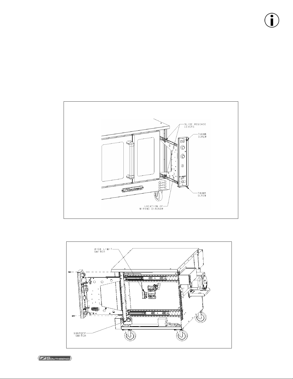
CONTROL PANEL ACCESS AND SHUT-OFF SWITCH
To access the control panel components, remove the remove the two thumbs screws at the top and bottom
of the control panel and slide the control panel out (see 1ST picture). A wiring diagram for the oven is
located on the side of the control panel assembly When the control panel is slid out, all power to the
control panel is cut off by a shut down switch that is located directly inside the opening and below
the control panel (see 2ND picture). To re-energize the controls for troubleshooting, pull the white plunger
on the shut down switch up.
To fully remove Control Panel, disconnect temp probe wires and harness connectors prior to pulling up on
slide release levers and removing.
Accessing Control Panel Components
INFOR MATION
Accessing Control Panel Components
P
ARTS MANUAL
1198301 P
AGE
5
Page 6
P
PARTS
P
ARTS
ARTS
F
ULL SIZE ELECTRIC CONVECTION OVENS
NOTICE
INSTALLATION OF OTHER THAN GENUINE SOUTHBEND PARTS WILL VOID THE WARRANTY
ON THIS EQUIPMENT.
The serial plate with voltage, model, and serial information is located inside the lower front panel of the
oven.
Replacement parts may be ordered either through a Southbend Authorized Parts Distributor or a
Southbend Authorized Service Agency. It is recommended to verify part numbers with a Southbend
Authorized Parts Supplier or the Southbend Parts/Service Dept. prior to ordering parts.
When ordering parts, you will need to supply the Model Number, Serial Number, Part Number,
Description, Finish, and Electrical Characteristics as applicable to the unit.
For parts not listed, contact a Southbend Authorized Parts Distributor or Southbend Authorized Service
Agency. You can find an Authorized Parts Distributor or Service Agency in your area by going to
www.southbendnc.com/service.html. If this information is not available, contact the Parts/Service Dept. at
Southbend to obtain specific part availability and information.
Index of Parts Diagrams
Page Number Description
7 Front Panel and Vent Cover Parts
8 Door Parts
9 Door Chain Mechanism Parts
10 Control Panel Parts for Models with Standard Controls (SC Models)
12 Control Panel Parts for Cycle/Cook and Hold Models (CCH Models)
14 Oven Interior and Fan Motor Parts
15 Oven Light Parts
16 Side Compartment Parts
17 Leg Parts for Single-Deck SilverStar Models
17 Leg Parts for Single-Deck Marathoner Gold Models
18 Storage Rack Parts
19 Double-Deck Oven Stacking Parts
20 Leg Parts for Double-Deck Ovens
P
AGE
6 P
ARTS MANUAL
1198301
Page 7
FULL SIZE ELECTRIC CONVECTION OVENS PARTS
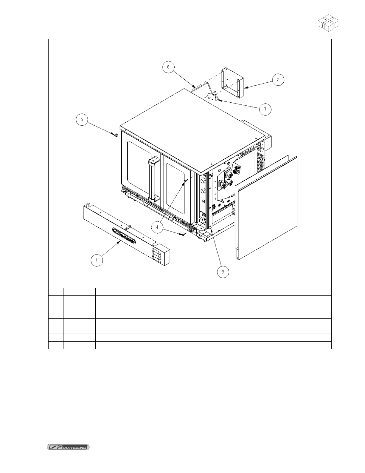
Front Panel and Vent Cover Parts
Key Part Number Qty Description
1 11 7 7 8 6 7 1 Panel, front louver, co
2 11 7 5 2 8 1 1 Cover, Vent
3 11 9 7 7 9 9 1 Control Panel Sealing Plate Assembly
4 11 7 9 7 0 3 2 Thumbscrew for control panel
5 11 7 5 4 0 1 1 Knob, Moisture vent
6 11 8 1 9 7 4 1 Cont rod, vent
7 11 7 5 2 7 7 1 Plate, vent
PARTS MANUAL 1198301 PAGE 7
PARTS
Page 8

PARTS FULL SIZE ELECTRIC CONVECTION OVENS
PARTS
Door Parts
Key Part Number Qty Description
1 11 9 7 2 6 9 1 Handle (part of left door assembly)
2 11 9 7 2 8 2 2 End Cap (part of left door assembly)
3 11 6 4 5 2 7 4 Bushing, bronze
4 11 6 4 5 4 7 2 Spacer, Door shaft
5 11 9 7 5 3 7 1 Center door seal, left door (60%)
6 11 9 7 5 3 8 1 Center door seal, right door (40%)
7 11 9 8 0 5 6 1 Door assembly, left, 60%, window, CO
1197732 1 Door assembly, left, 60%, solid, CO
8 11 9 8 0 5 7 1 Door assembly, right, 40%, window, CO
1197736 1 Door assembly, right, 40%, solid, CO
9 11 8 1 8 6 5 2 Door seal, left & right, CO
10 1 1 9 1 4 4 4 1 Door seal, bottom, metal, CO
11 1 1 9 7 5 0 6 1 Door seal assembly, bottom, CO
12 1 1 9 7 5 0 2 1 Door seal assembly, top, CO
13 1 1 9 7 7 2 3 1 Door Stop, bottom
PAGE 8 PARTS MANUAL 1198301
Page 9

FULL SIZE ELECTRIC CONVECTION OVENS PARTS
Door Chain Mechanism Parts
Key Part Number Qty Description
1 1179937 1 Door Chain assembly
2 1172326 2 Screw, #4-40 x 3/4, zinc plated
3 1177567 1 Switch, door, spdt, 15 amp
4 1172327 2 Nut #4-40, zinc plated, hex
5 1181956 1 Bracket, door switch
PARTS
PARTS MANUAL 1198301 PAGE 9
Page 10

PARTS FULL SIZE ELECTRIC CONVECTION OVENS
PARTS
Control Panel Parts for Models with Standard Controls (SC Models)
See drawing on following page.
Key Part Number Qty Description
- 1198034 1 Control panel s/a, SC, 60Hz, G-Series, 208/380/415V (assembled, w/o wiring harness)
- 1198035 1 Control panel s/a, SC, 60Hz, G-Series, 480V (assembled, w/o wiring harness)
- 1198036 1 Control panel s/a, SC, 60Hz, S-Series, 208/380/415V, w/lights (assembled, w/o wiring harness)
- 1198038 1 Control panel s/a, SC, 60Hz, S-Series, 208/380/415V, w/o lights (assembled, w/o wiring harness)
1198040 1 Control panel s/a, SC, 50Hz, S-Series, 208/380/415V, w/lights (assembled, w/o wiring harness)
- 1198041 1 Control panel s/a, SC, 50Hz, S-Series, 208/380/415V, w/o lights (assembled, w/o wiring harness)
- 1198037 1 Control panel s/a, SC, 60Hz, S-Series, 480V, w/lights (assembled, w/o wiring harness)
- 1198039 1 Control panel s/a, SC, 60Hz, S-Series, 480V, w/o lights (assembled, w/o wiring harness)
* 1179593 1 Wiring harness, SC
1 1197782 1 Frame Assembly, Std., Slide
2 1198001 1 Polypanel, G-Series
1198000 1 Polypanel, SL-Series
3 1177541 1 Rocker switch-DPST- (on-off)
4 1177540 2 Rocker switch-SPDT (on-on)
5 1170350 1 Light, amber, 240V, signal
6 6600334 2 Screw, 6-32, 3/8, Self-tapping
7 1170424 2 Fuse holder
8 1170425 2 Fuse, 12 amp #LP-CC-12 low peak
9 1177789 1 Rocker switch-SPST momentary (for models with the optional oven light)
1177642 1 Plug, square (for models without the optional oven light)
10 1 1 9 8 0 8 4 1 Push mount wire tie
11 1 1 7 0 3 3 6 1 Marker strip
12 1 1 7 0 3 3 5 1 Terminal block (supplied w/harness)
13 2 0 0 1 3 4 7 3 Locknut, 8-32
14 1 1 4 6 3 9 7 3 Screw 8-32 x 5/8 s/steel pan head
15 1 1 8 1 9 9 8 1 Temperature control board/analog potentiometer
16 1 1 7 5 7 0 8 1 Buzzer, adjustable, 240VAC
17 1 1 7 6 4 1 6 1 Timer, motorized, 240V, 60Hz
1176436 1 Timer, motorized, 240V, 50Hz
* 1181996 1 Temperature probe
18 1 1 7 0 3 3 7 2 Knob for temperature control bd. and timer
19 1 1 4 6 3 1 9 1 Screw 6-32 x 1/2 round head
* 1062100 1 Wire nut (for models without the optional oven light)
* 1166609 10 Ties, cable, ty-rap, 4"
* not shown on drawing.
PAGE 10 PARTS MANUAL 1198301
Page 11

F
ULL SIZE ELECTRIC CONVECTION OVENS
P
Control Panel Parts for Models with Standard Controls (SC Models)
See parts list on previous page.
ARTS
P
ARTS MANUAL
1198301 P
AGE
PARTS
11
Page 12

PARTS FULL SIZE ELECTRIC CONVECTION OVENS
PARTS
Control Panel Parts for Cycle/Cook and Hold Models (CCH Models)
See drawing on following page.
Key Part Number Qty Description
- 1198010 1 Control panel s/a, CCH, 60Hz, G-Series, 220/380/415V (assembled, w/o wiring harness)
- 1198011 1 Control panel s/a, CCH, 60Hz, G-Series, 480V (assembled, w/o wiring harness)
- 1198012 1 Control panel s/a, CCH, 60Hz, S-Series, 220/380/415V, w/lights (assembled, w/o wiring harness)
- 1198014 1 Control panel s/a, CCH, 60Hz, S-Series, 220/380/415V, w/o lights (assembled, w/o wiring harness)
- 1198013 1 Control panel s/a, CCH, 60Hz, S-Series, 480V, w/lights (assembled, w/o wiring harness)
- 1198015 1 Control panel s/a, CCH, 60Hz, S-Series, 480V, w/o lights (assembled, w/o wiring harness)
* 1180484 1 Wiring harness, CCH
1 1197783 1 Frame Assembly, CCH, Slide
2 1177540 2 Rocker switch-SPDT (on-on)
3 1198003 1 Polypanel, CCH, G-Series
1198002 1 Polypanel, CCH, S-Series
4 1177541 1 Rocker switch-DPST- (on-off)
5 1170424 2 Fuse holder
6 1170425 2 Fuse, 12 amp #LP-CC-12 low peak
7 1177789 1 Rocker switch-SPST momentary (for models with the optional oven light)
1177642 1 Plug, square (for models without the optional oven light)
8 1198084 1 Wire Tie, push mount
9 1170336 1 Marker strip
10 1 1 7 0 3 3 5 1 Terminal block
11 2 0 0 1 3 4 7 4 Locknut, 8-32
12 1 1 4 6 3 9 7 4 Screw 8-32 x 5/8 s/steel pan head
13 1 1 8 0 4 0 4 4 Spacer, control
14 1 1 8 0 4 0 7 1 Control, CCH
15 1 1 4 6 4 0 0 4 Nut, #6-32 hex
16 1 1 8 0 4 9 9 1 Relay, 208/240V
1181996 1 Temperature probe
* 1166609 10 Ties, cable, ty-rap, 4"
* not shown on drawing.
PAGE 12 PARTS MANUAL 1198301
Page 13

F
ULL SIZE ELECTRIC CONVECTION OVENS
P
Control Panel Parts for Cycle/Cook and Hold Models (CCH Models)
See parts list on previous page.
ARTS
P
ARTS MANUAL
1198301 P
AGE
PARTS
13
Page 14

PARTS FULL SIZE ELECTRIC CONVECTION OVENS
PARTS
Oven Interior and Fan Motor Parts
Key Part Number Qty Description
1 11 6 0 2 8 9 4 Thumb screw 1/4-20 x 3/4
2 11 8 1 9 7 7 1 Baffle, oven, cr, Elec., C/O
3 11 6 6 8 1 9 4 Nut, 1/4 x 20, speed
4 11 7 5 4 1 2 2 Bracket, baffle mtg
5 11 7 5 7 1 5 1 Bracket, baffle locating
6 11 7 5 2 6 3 1 Element asm. 208V
1175264 1 Element asm. 240V
1175414 1 Element asm. 380V
1175265 1 Element asm. 480V
7 11 8 9 8 2 1 5 Rack, oven, shallow, mg
1189860 5 Rack, oven, bakery. mg
8 11 8 9 8 2 0 2 Rack guide, 11 pos, shallow
1189822 2 Rack guide, 11 pos, bakery
9 66 6 0 8 Clip, side rack support
10 1 1 7 5 1 4 6 1 Bolt, carriage, 3/8, ss
11 1 1 7 5 4 0 7 1 Tube, w/a, moisture vent
1080303 1 Gasket, silicone, .062 ga.
12
13 1 1 7 9 1 0 4 1 Blower wheel, G & E series
* 1 1 7 9 1 0 0 ** Puller disk
14 1 1 7 5 1 4 6 4 Nut, 3/8, ss
15 1 1 7 5 7 0 5 1 Pocket w/a, blower motor
16 1 1 9 5 4 3 9 2 Insulation, elements
17 1 1 7 5 2 5 6 1 Cover, rear, elements
18 1 1 7 5 5 6 8 1 Motor, 2sp, 230V, 50/60 cycle
19 1 1 4 6 2 6 4 4 Screw, 1/4-20 x 2
* not shown on drawing.
** SERVICE TOOL; may be needed to remove blower wheel.
PAGE 14 PARTS MANUAL 1198301
Page 15

FULL SIZE ELECTRIC CONVECTION OVENS PARTS
Oven Light Parts
Key Part
Number
1 1 1 8 1 8 0 6 1 Retainer, glass, co
2 1 1 8 1 8 0 7 1 Glass, bulb cover, co
1197730 1 Seal, Teflon
3
4-10 11 8 1 8 2 8 1 Oven light subassembly, co (parts 3 through 7, assembled)
4 1 1 6 0 0 0 9 2 Bulb, oven light, 40 watt, clear
5 P 6 4 9 7 2 Gasket, Teflon, white
6 1 1 8 1 8 0 5 1 Light box, co
7 1 1 6 0 0 3 2 2 Gasket, light socket, .062 ga
8 1 1 4 6 3 2 2 4 Screw,8-32X1 round head
9 2 0 0 1 3 4 7 4 Nut, Locking, KEPS
10 1160010 2 Socket, oven light asm
* not shown on drawing.
Qty Description
PARTS
PARTS MANUAL 1198301 PAGE 15
Page 16

PARTS FULL SIZE ELECTRIC CONVECTION OVENS
PARTS
Side Compartment Parts
Key Part Number Qty Description
1 11 9 7 8 0 5 2 Slide mounting asm. (std depth)
1197806 2 Slide mounting asm. (bakery depth)
2 11 9 7 7 7 7 2 Shim,Slide support
3 11 8 8 5 2 5 4 Bolt, Hex, flng hd 1/4-20 x 1.00 lg, ss
4 11 6 1 9 9 8 1 Switch, High limit
5 11 7 9 6 8 0 1 Contactor, element power
6 11 7 5 7 2 4 2 Mntg brkt, contactor
7 11 7 5 5 4 7 1 Lug, grounding
8 11 7 7 5 6 6 1 Switch, shutdown, SPDT, 15 amp
9 11 9 7 5 8 6 1 Brkt, switch mount
10 1 1 9 7 7 5 6 1 Pivot, S/O Switch
11 1 1 9 8 0 0 6 1 Spacer, pivot
12 1 1 9 8 0 0 4 1 Bolt, shoulder, 5/16 x 1-1/2 lg. (1/4-20 thread)
13 1 1 8 1 9 9 6 1 Probe, Thermostat
14 1 1 7 0 3 2 8 1 Brkt, probe
15 1 1 7 1 7 1 0 1 Clamp brkt, probe
16 1 1 9 7 7 9 9 1 Sealing plate asm.
17 1 1 7 0 3 7 3 1 Transformer, (480V units ONLY)
18 P E - 0 2 4 1 Term block end (380V & 415V units ONLY)
19 P E - 0 2 3 3 Term block (380V & 415V units ONLY)
PAGE 16 PARTS MANUAL 1198301
Page 17

FULL SIZE ELECTRIC CONVECTION OVENS PARTS
Leg Parts for Single-Deck Models
Key Part Number Qty Description
1 1177850 4 Single deck leg (for legs with feet or casters)
2 1174266 4 Adjustable foot for leg
* 1173584 4 Flanged foot (optional replacement for adjustable foot 1174266)
3 1174264 2 Caster with brake
4 1174263 2 Caster without brake
* 1174265 1 Set of four casters (two with brake, two without brake)
* 1146213 20 3/8 x 16 x 1 hex head bolt
* 1146513 20 3/8 lock washer
* 1146522 20 3/8 flat washer
* not shown on drawing.
PARTS MANUAL 1198301 PAGE 17
PARTS
Page 18

PARTS FULL SIZE ELECTRIC CONVECTION OVENS
PARTS
Storage Rack Parts
Key Part Number Qty Description
- 11 8 4 0 4 4 1 Cooling pan kit, with shelf, bakery depth
- 11 8 4 0 4 6 1 Cooling pan kit, with shelf, shallow depth
1 11 8 4 0 2 2 2 Rack hanger, G/E ser co
2 11 8 4 0 2 5 1 Stop channel
3 66 6 0 8 Clip, side rack support
4 11 7 5 4 3 8 2 Rack guide, 11 pos. shallow
1175439 2 Rack guide, 11 pos. bakery
5 11 8 4 0 1 9 1 Shelf, open rack, shallow
1184023 1 Shelf, open rack, bakery
* 1 1 4 6 3 0 4 18 10 x 1/2 Phillips screw
* not shown on drawing.
PAGE 18 PARTS MANUAL 1198301
Page 19

FULL SIZE ELECTRIC CONVECTION OVENS PARTS
1
2
Double-Deck Oven Stacking Parts
Key Part Number Qty Description
1 11 4 6 2 1 3 2 Bolts
2 11 7 5 0 8 5 1 Tie bracket
PARTS
PARTS MANUAL 1198301 PAGE 19
Page 20

PARTS FULL SIZE ELECTRIC CONVECTION OVENS
PARTS
121
3
4
Leg Parts for Double-Deck Ovens
Key Part Number Qty Description
1 11 7 2 7 8 8 4 Leg pad
2 11 7 4 2 5 9 4 SS leg, 3/4" stud
* 1 1 7 4 2 6 0 1 Leg package (set of four legs only)
3 11 7 4 2 6 4 2 Caster with brake
4 11 7 4 2 6 3 2 Caster without brake
* 1 1 7 4 2 6 5 1 Set of four casters (two with brake, two without brake)
* 1 1 4 6 2 1 3 16 3/8 x 16 x 1 hex head bolt
* 1 1 4 6 5 1 3 16 3/8 lock washer
* 1 1 4 6 5 2 2 16 3/8 flat washer
* not shown on drawing.
PAGE 20 PARTS MANUAL 1198301
Page 21

F
ULL SIZE ELECTRIC CONVECTION OVENS
User & Maintenance Notes:
P
ARTS MANUAL
1198301 P
AGE
21
Page 22

F
PARTS MANUAL
G & SL-SERIES
ELECTRIC CONVECTION OVENS
ULL SIZE ELECTRIC CONVECTION OVENS
A product with the Southbend name incorporates the best in durability and low maintenance. We
all recognize, however, that replacement parts and occasional professional service may be
necessary to extend the useful life of this unit. When service is needed, contact a Southbend
Authorized Service Agency, or your dealer. To avoid confusion, always refer to the model number,
serial number, and type of your unit.
Southbend
1100 Old Honeycutt Road, Fuquay-Varina, NC 27526
www.southbendnc.com
P
AGE
22 P
ARTS MANUAL
1198301
 Loading...