

Page 1
IMPORTANT FOR FUTURE REFERENCE
Please complete this information and retain this
manual for the life of the equi pment:
Model #: __________________________
Serial #: __________________________
Date Purchased: ___________________
OPERATOR’S MANUAL
Super Simple Steam
SEZ Series Countertop Steamers
Models SEZ-3 & SEZ-5
Model SEZ-3
! WARNING
Improper installation, operation, service, or maintenance can cause property damage, injury, or death.
Read this manual thoroughly before installing and operating this equipment.
1100 Old Honeycutt Road, Fuquay-Varina, NC 27526
(800) 348-2558 or (919) 552-9161 • FAX (800) 348-2558 or (919) 552-9798
MANUAL 1181587
$18.00
COUNTERTOP STEAMER
MANUAL SECTION ST
Page 2
SEZ SERIES COUNTERTOP STEAMERS
SAFETY PRECAUTIONS
Before installing a nd opera ting this equipm ent, be sure e ver yone invol ved in its operat ion is f ully tr ained and
aware of precautions. Accidents and problems can be caused by failure to follow fundamental rules and
precautions.
The following s ymbols, found throughout this manual, alert you to potentia lly dangerous conditions to the
operator, service personnel, or to the equipment.
! DANGER
! WARNING
! CAUTION
NOTICE
This symbol warns of im mediate hazards which will result in severe injury or
death.
This symbol refers to a p otential hazard or uns afe practice wh ich could result in
injury or death.
This symbol refers to a p otential hazard or uns afe practice wh ich could result in
injury, product damage, or property damage.
This symbol refers to information that needs special attention or must be fully
understood, even though not dangerous.
! WARNING
FIRE HAZARD
For your safety, do n ot store or use gasol ine or other flamm able vapors and liquids in the vicinit y of
this or any other appliance.
Keep area around appliances free and clear of combustibles.
! WARNING
SHOCK HAZARD
Do not open panels that require use of tools.
Unit must be cleaned daily and properly maintained to reduce chances of unsafe operating
conditions.
! WARNING
BURN HAZARD
Stand back when opening doors - hot steam or hot water may escape from steamer.
NOTICE
Be sure this Operator’s Man ual and important papers ar e given to the proper authorit y to retain for
future reference.
PAGE 2OPERATOR’S MANUAL 1181587
Page 3

SEZ SERIES COUNTERTOP STEAMERS TABLE OF CONTENTS
Congratulations! You have purchased on e of the finest p ieces of heav y-duty comm ercial cook ing equipm ent
on the market.
You will find that your new equipm ent, like all Southbend equipment, has been desig ned and m anufactured
to meet the toughest standards in the indus try. Each piece of Southbend equipm ent is carefully eng ineered
and designs are verified through laboratory tests and field installations. With proper care and field
maintenance, you will experience years of reliable, trouble-free operation. For best results, read this
manual carefully.
RETAIN THIS MANUAL FOR FUTURE REFERENCE.
Table of Contents
Specifications..........................................................................................................................4
Installation...............................................................................................................................6
Operation ..............................................................................................................................12
Cooking Hints........................................................................................................................13
Cleaning................................................................................................................................16
Troubleshooting ....................................................................................................................18
Parts......................................................................................................................................40
Read these instructions carefully before attempting installation. Installation and initial startup should be
performed by a qualified installer. Unless the installation instructions for this product are followed by a
qualified service tech nician (a person experienced in and knowledge able with the insta llation of comm ercial
gas an/or electric cooking equipm ent) then the terms and conditi ons on the Ma nufactur er’s Lim ited W arranty
will be rendered void and no warranty of any kind shall apply.
In the event you have questions concerning the installation, use, care, or service of the product, write to:
Technical Service Department
Southbend
1100 Old Honeycutt Road
Fuquay-Varina, North Carolina 27526 USA
The serial plate is located on the right side of the unit near the back and top.
OPERATOR’S MANUAL 1181587 PAGE 3
Page 4
SPECIFICATIONS SEZ SERIES COUNTERTOP STEAMERS
SPECIFICATIONS
SPECIFICATIONS
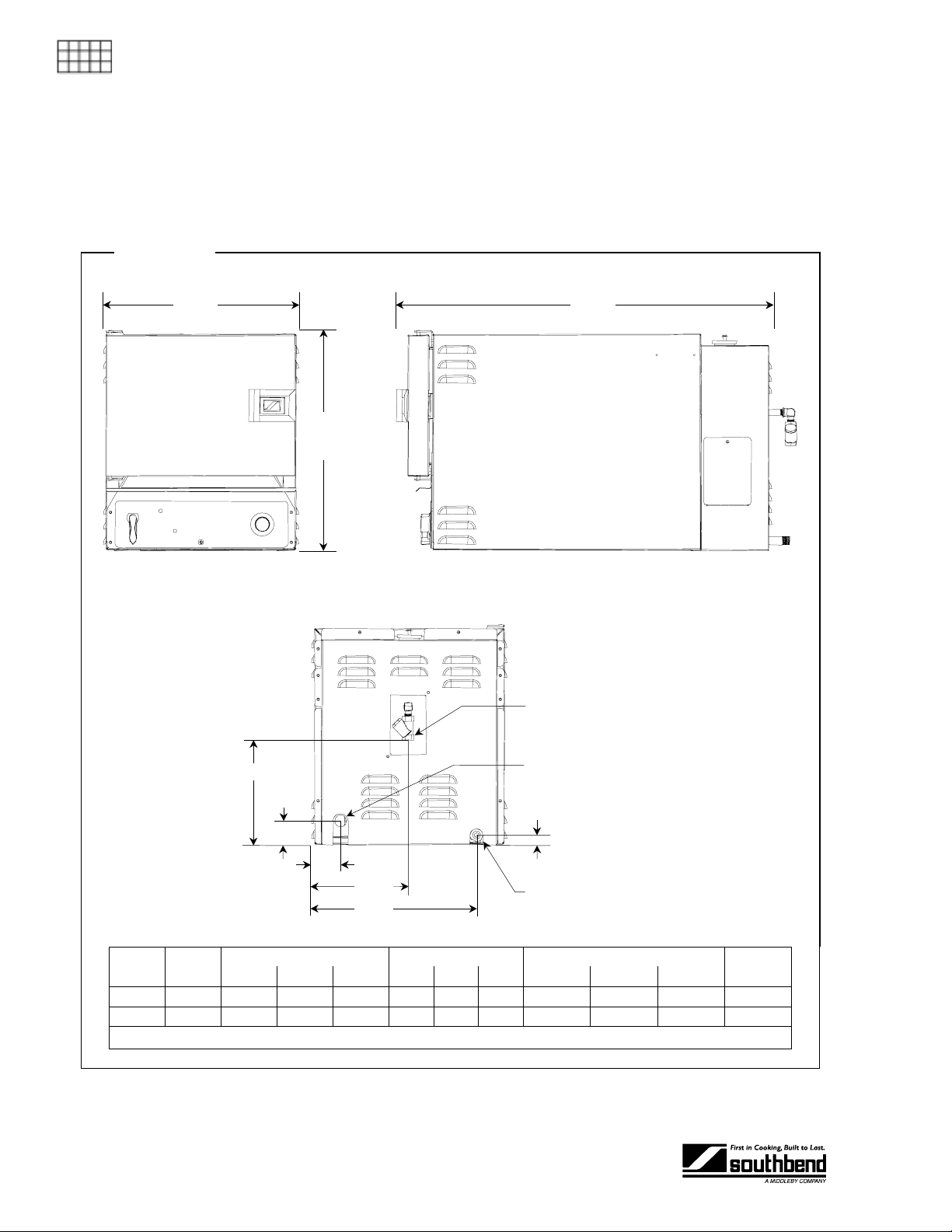
DIMENSIONS
Figure 1
16.3"
33.5"
See
table
below
SIDE VIEWFRONT VIEW
REAR VIEW
Water Inlet
8.8"
2.0"
2.4"
8.1"
13.6"
Model
SEZ-3 18.1" 13.5" 22.0" 9.5" 6 3 2 19.5" 31.5" 28.5" 150 lbs.
SEZ-5 24.1" 13.5" 22.0" 15.5" 9 5 3 19.5" 31.5" 34.5" 175 lbs.
* “Pan Capacity” is the number of 1", 2.5", or 4" high standard pans (12" wide x 20" deep) that the steamer will hold.
PAGE 4OPERATOR’S MANUAL 1181587
Overall
Height
Interior Dimensions Pan Capacity* Crate Dimensions
Width Depth Height 1" 2.5" 4" Width Depth Height
Electric Connection
0.8"
Water Drain
Crated
Weight
Page 5
SEZ SERIES COUNTERTOP STEAMERS SPECIFICATIONS
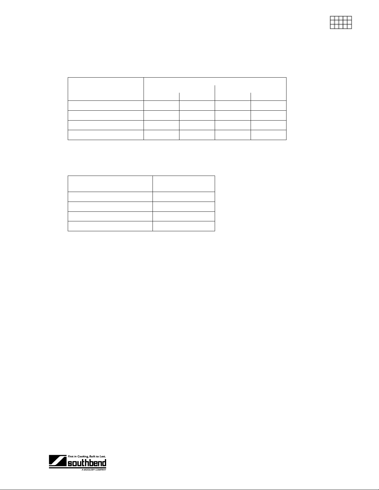
ELECTRIC REQUIREMENTS
One electric connection is required to the f use block of the steam er. All units shipped per customer order,
three phase or single phase (a kit is available f or field conversion to thr ee phase or single phase) . Circuit
must be wired for the maximum amps at required voltage.
Total Connected Amps
Voltage
208 V 44 25 57 33
220 V 41 24 54 31
240 V 38 22 49 29
480 V 19 11 25 15
Model SEZ-3 Model SEZ-5
1 Phase 3 Phase 1 Phase 3 Phase
WATER REQUIREMENTS
To meet warranty requirements, the water supply must be as follows:
SPECIFICATIONS
Connection
Pressure 30 to 60 PSI
Total Dissolved Solids (TDS) 60 PPM
Hardness 2 grains or 35 PPM
pH 7.0 to 7.5
1/4" NPT (female)
cold water
Typical usage is 0.02 gpm. Maximum instantaneous usage is 0.12 gpm.
In order to minimize service problems and to meet the warranty requirements, a water treatment system
(softener) is recommended when water quality does not meet the limits stated above.
DRAIN REQUIREMENTS
The drain outlet has a 3/8" NPT (male) c onnector. DO NO T direc tly connect th e drain to a plum bing system
unless you also install an “open funnel” downstream of this connection. There must be no back-flow or backpressure into the drain connection!
CONSTRUCTION SPECIFICATIONS
Exterior: Type 304 stainless steel with #3 sanitary finish.
Interior: #304 stainless steel.
Power Source: One electric power sourc e for controls and heating e lements, as well as one ground wire.
A positive ground connection is essential.
Cooking Compartment: Fully insulated.
CONTROLS
ON/OFF Lever: In the “OFF” position, the po wer is of f and the dr ain valve is open. In the “ON” position, the
power is on and the drain valve is closed.
60 Minute Timer: Tim e can be set between 1 and 60 minutes. W hen time expires, b uzzer so unds. Buzzer
can be disabled b y turning th e knob t o manual position . Tim er has no ef fect on the operatio n of the
steamer.
“SERVICE REQUEST” Light: Unit signals when service is needed.
“ON” Light: Indicates power is on.
OPERATOR’S MANUAL 1181587 PAGE 5
Page 6
INSTALLATION SEZ SERIES COUNTERTOP STEAMERS
INSTALLATION
Do not locate unit adjacent t o any high heat or greas e pr od uc in g p iece of eq ui pment, such as a range
top, griddle, fryer, etc., t hat could allow radia nt heat to raise the ex terior temperature of the steamer
body above 130°F (54°C). DO NOT MOUNT ABOVE OTHER COOKING EQUIPMENT.
INSTALLATION
These installation procedures must be followed by qualified personnel or warranty will be void.
Local codes regarding install ation var y greatly from one area to an other. T he National F ire Protec tion
Association, Inc. states in its NFPA 96 latest edition that local codes are the “authority having
jurisdiction” when it com es to installation r equirements for equipment. Theref ore, installations shou ld
comply with all local codes.
The unit, when installed, must be electrically grounded and comply with local codes, or in the
absence of local codes with the National El ec tr ical Code ANSI /NF P A 70-lat es t edit ion .
! CAUTION
NOTICE
Canadian installation must comply with CSA-Standard (C22.2 No. 109-M1981 General
Requirements-Canadian Electrical Code, Part II. 109-M1981) Commercial Cooking Appliances.
NOTICE
EXHAUST FANS AND CANOPIES: It is recommended that the steamer be installed under a
ventilation hood. Consult local codes for proper installation of hoods. Proper ventilation is the owner’s
responsibility. Any problem due to improper ventilation will not be covered by warranty.
LEVELING: Unit must be level to assure maximum performance. Improper leveling may void
warranty.
Step 1: Unpacking
IMMEDIATELY INSPECT FOR SHIPPING DAMAGE
All containers shou ld be examined for dam age before and during unlo ading. The freight car rier has
assumed responsibility for its safe transit and delivery. If damaged equipment is received, either
apparent or concealed, a claim must be made with the delivering carrier.
Apparent damage or l oss m u st be noted on the freight b ill at the t im e of deliver y. T he f reight bi ll m ust
then be signed by the c arrier representative (Dr iver). If the bill is not s igned, the carrier ma y refuse
the claim. The carrier can supply the necessary forms.
A request for insp ection must be m ade to the carrier within 15 da ys if there is concea led damage or
loss that is not apparent until after the equipment is uncrated. The carrier should arrange an
inspection. Be certain to hold all contents plus all packing material.
PAGE 6OPERATOR’S MANUAL 1181587
Page 7
SEZ SERIES COUNTERTOP STEAMERS INSTALLATION
Step 2: Installation
1. Uncrate carefully. Report any hidden damage to the freight carrier IMMEDIATELY.
2. Do not remove any tags or labels until unit is installed and working properly.
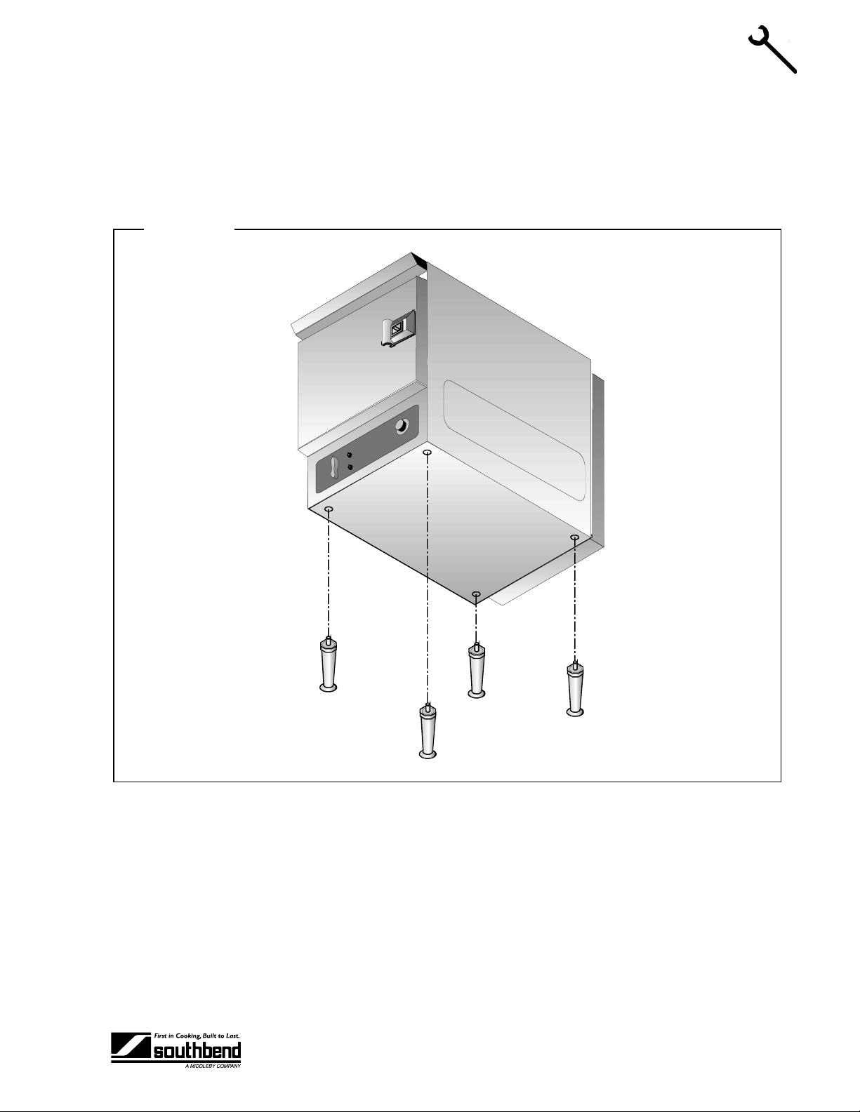
3. If unit is to be installed on legs, locate legs and install as shown in Figure 2 below.
Figure 2
INSTALLATION
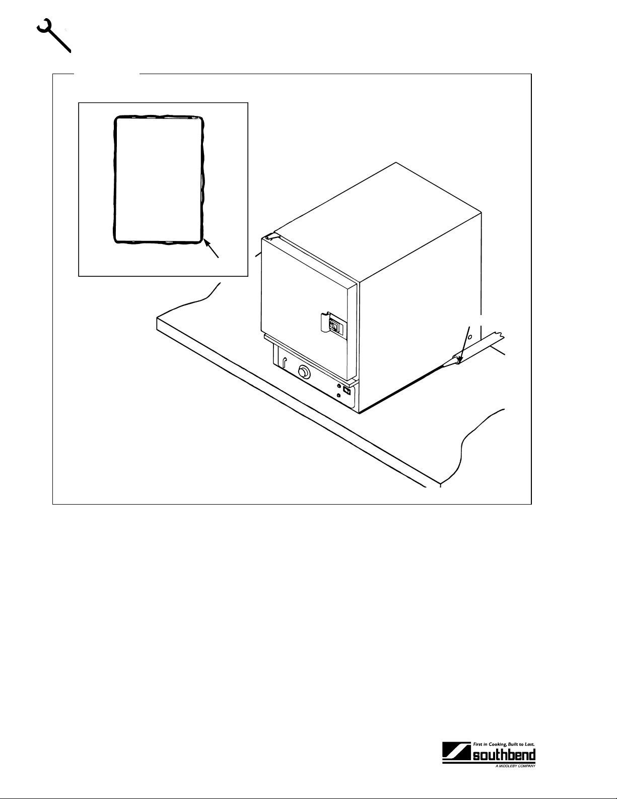
4. If the un it is to b e i ns talled on a counter top or oth er s ur f ac e with out using l egs , th e u nit must be sealed
to the surface to prevent any water , grease, etc., from accumulating under the s teamer. The steam er
can be bolted to the co unter but wi ll st ill h ave to be s eale d. T he instal ler m a y use G .E. or Do w Cor ning
RTV type sealant. Consult local code for exact requirements. See Figure 3 below.
OPERATOR’S MANUAL 1181587 PAGE 7
Page 8
INSTALLATION
INSTALLATION SEZ SERIES COUNTERTOP STEAMERS
Figure 3
Steamer
BOTTOM VIEW
Sealer
Sealant
PAGE 8OPERATOR’S MANUAL 1181587
Page 9
SEZ SERIES COUNTERTOP STEAMERS INSTALLATION
Step 3: Electric Connection
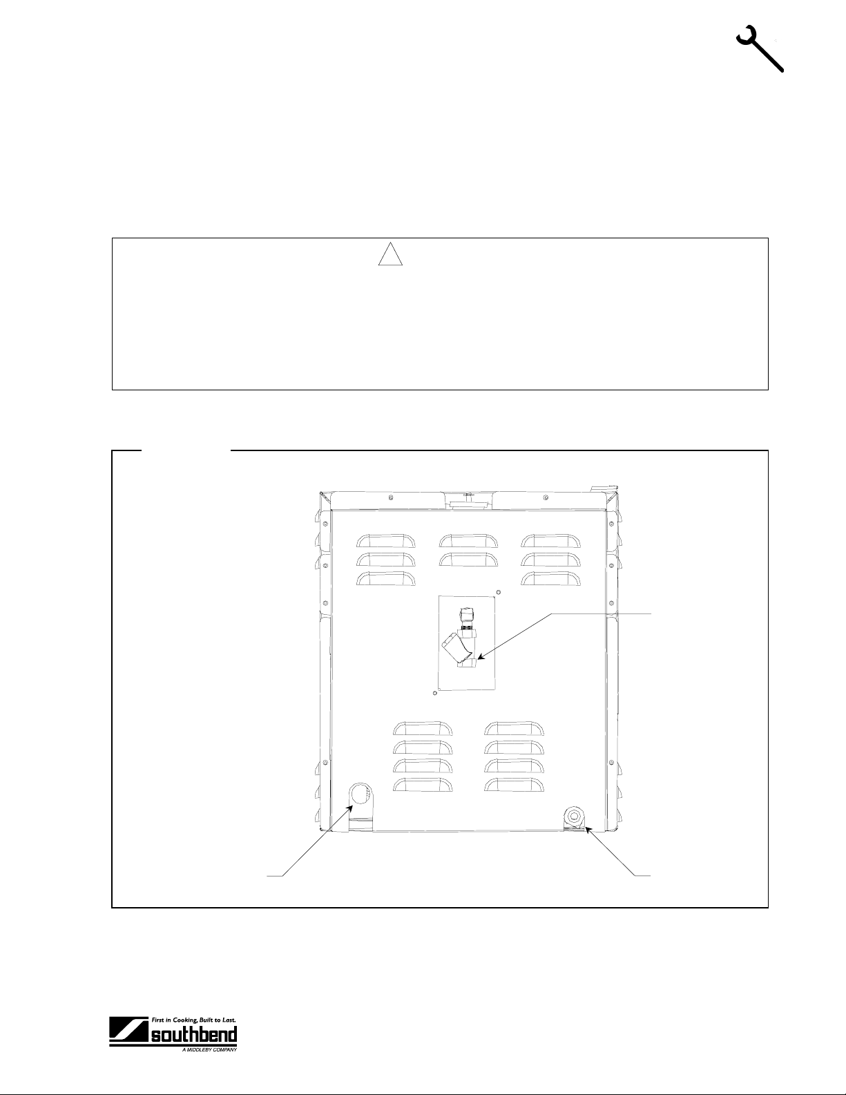
A field connection Fuse Block is located at the rear of the unit, lower left side when facing the back of the unit
(see Figure 4 below). A hole is provided for a 3/ 4" conduit fitting (solid or flex). The rear cover m ust be
removed to gain access to fuse block (see Figure 9 on page 26).
Be sure that the input voltage matches the requirement on the serial plate. The unit is factory wired per
customer order.
! WARNING
A POSITIVE GROUND CONNECTION IS ESSENTIAL. DO NOT ALLOW ANY TAMPERING OR
ADJUSTMENT OF ANY CONTROL OR WIRING. T HE UNIT IS FACTORY SET. ADJUSTING ANY
INTERNAL COMPONENT OTHER THAN THE MAIN FUSE BLOCK CAN VOID THE WARRANTY.
THIS UNIT REQUIRES A KIT TO BE FIELD CONVERTED FROM THREE-PHASE TO SINGLEPHASE OR VICE-VERSA. CONSULT FACTORY FOR PHASE CHANGES.
All 208-220-240 and 480 volt units will h ave three fuse bl ock sections , “L1-L2-L3”, for us e with either 3-wir e
3-phase or 2-wire, single-phase, 50 or 60 Hz.
Figure 4
INSTALLATION
Electric Connection
Water Inlet
REAR VIEW
Water Drain
OPERATOR’S MANUAL 1181587 PAGE 9
Page 10
INSTALLATION SEZ SERIES COUNTERTOP STEAMERS
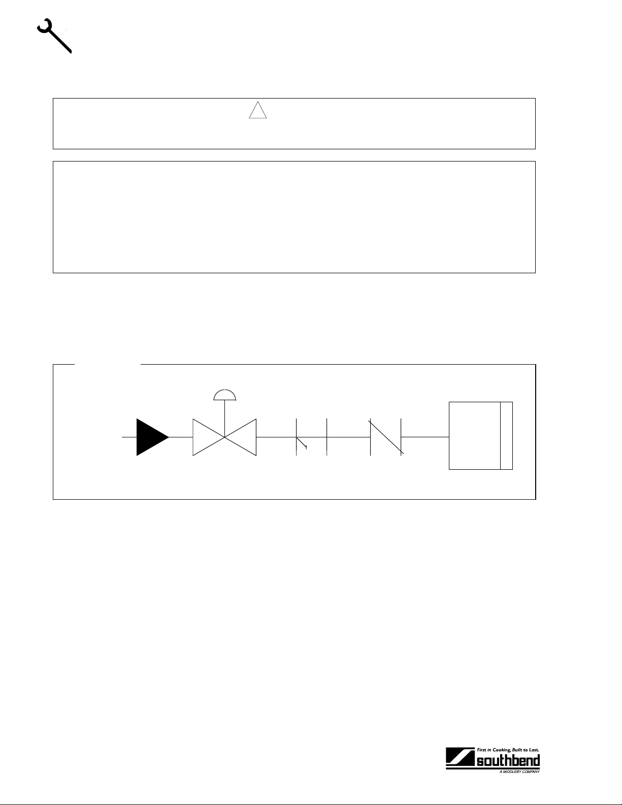
Step 4: Water Connection
! WARNING
Do not connect steamer to a hot water line. A hot water connection will damage the steamer.
NOTICE
To meet warranty requirements, the supply water must meet the following specifications:
INSTALLATION
Connect a cold water line to the water inlet strainer on the back of the steamer, as shown in Fig ure 4 on
page 9. The connector on the unit is 1/4" NPT female.
NOTE: To facilitate cleaning , and allo w acces s to rear of un it, f lexi ble c onn ec tio ns are r ec om mended. A shut
off valve at (or near) the rear of the unit is highly recommended. See Figure 5 below.
Pressure 30 to 60 PSI
Total Dissolved Solids (TDS) 60 PPM
Hardness 2 grains or 35 PPM
pH 7.0 to 7.5
Figure 5
Cold
Water
Supply
Shut Off
Valve
Filter
Steamer
Check
Valve
PAGE 10 OPERATOR’S MANUAL 1181587
Page 11
SEZ SERIES COUNTERTOP STEAMERS INSTALLATION
A
A
A
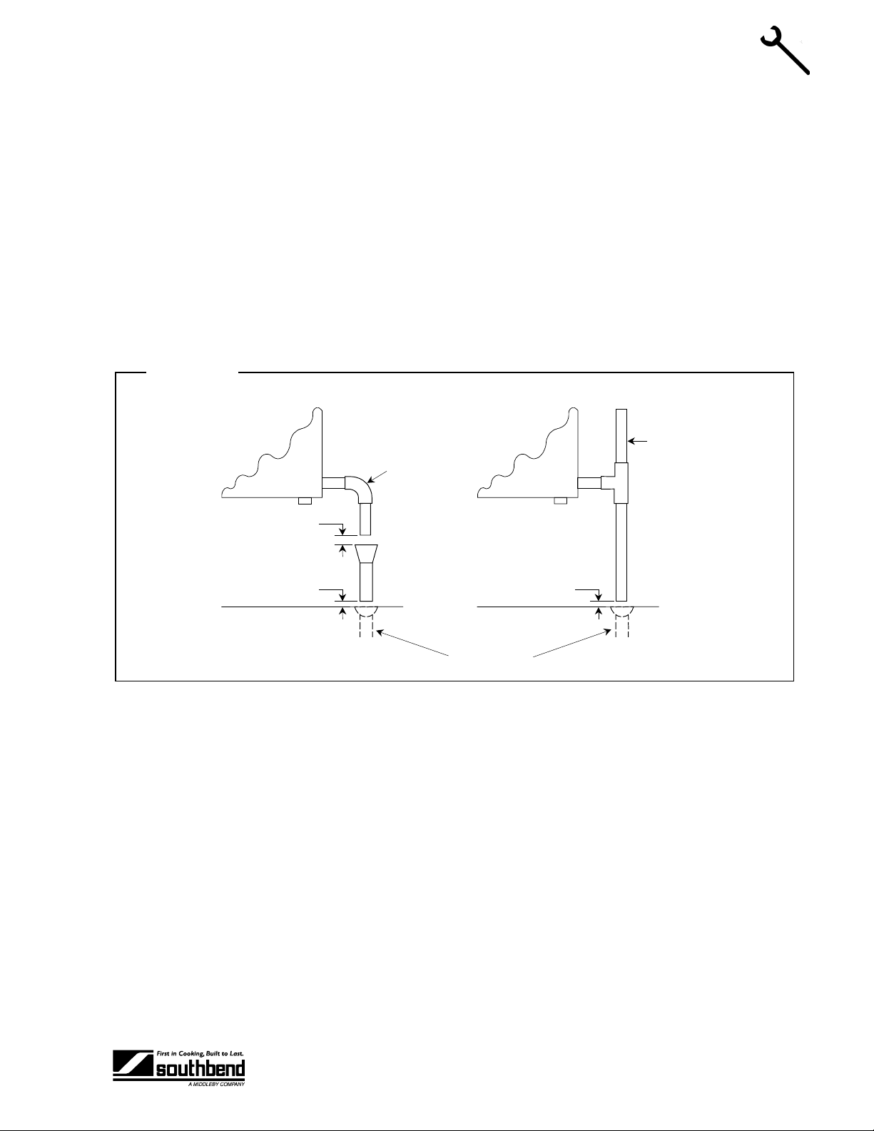
Step 3: Drain Connection
The drain outlet is located on the back of the st eam er, as shown i n Figur e 4 on page 9. T h e drain c onnector
on the unit is 3/8" NPT male.
Position the unit near, but not on top of , an open floor drain. DO NOT directly plum b to the unit unl ess you
also install an “open funnel” do wnstream of this connecti on in the drai n system . Mak e the dr ain l ine fr om the
unit to the air gap above the “open funnel” as short as possible. There should be no horizontal piping
between the unit and the air gap abo ve the “open funnel.” The “ope n funnel” is intended to elim inate any
water from entering the steamer because of a blocked drain, and it also pr events any back pr essure within
the steamer cavity. Any connectio n that a llows the build- up of bac k press ure in the un it (s uch as a red uctio n
in pipe size to a line smaller than 3/8", or more than one 9 0- degre e a ngle in the line pr ior to the “ ope n f unne l”
drain discharge point) m a y cause pers o nal or prop er ty damage and will t heref or e voi d th e warra nty. The unit
is a pressureless , free-ventin g steam c ooker and will not operate properly unles s the drain l ine is shor t, at a
steep angle, and open! See Figure 6 below.
Figure 6
Stand
Pipe
90°
INSTALLATION
ir Gap
ir Gap
ir Gap
Floor Drains
OPERATOR’S MANUAL 1181587 PAGE 11
Page 12
OPERATION SEZ SERIES COUNTERTOP STEAMERS
OPERATION
STARTUP
1. Turn lever to “ON” position.
2. Unit will fill automatically and be ready for operation in 15 minutes.
To meet warranty requirements, supply water must meet the following specification:
OPERATION
OPERATION
NOTICE: WATER SPECIFICATION
Total Dissolved Solids (TDS) ...........60 PPM
Hardness ..........................................2 Grains or 35 PPM
pH Factor..........................................7.0 to 7.5
! CAUTION
HOT STEAM WILL ESCAPE WHEN DOOR IS BEING OPENED. TO PREVENT BURNS KEEP
HANDS AND FACE AWAY FROM STEAM.
If “SERVICE REQU EST” light illuminates during op eration, contact your authori zed service agency
immediately.
1. Suggested cooking times for various foods are shown in the table in the following section.
2. Pan specifications are shown on specifications page (page 4).
3. The door may be opened or closed at any time.
4. Timer can be used as desired, but it has no effect on the operation of the unit!
5. Unit will autom aticall y idle at opera ting temperature when a nd if the door is cl osed a nd there is no f ood
in the cavity.
SHUTDOWN
1. Turn lever to the “OFF” position.
2. Remove pan guides.
3. Clean all interior surfaces with soap, water, and a non-metallic pad. Occasional use of a deliming
solution such as Lime-A-Way is recommended. RINSE THOROUGHLY WITH CLEAN WATER.
4. Ens ure dr ai n open ing is clear .
5. Replace pan guides.
6. Leave the door open at night after cleaning to prolong the life of the gasket.
NOTICE
DO NOT USE high-chlorine or bleach solution for cleaning the door gasket.
DO NOT USE steel wool or other metallic pads in the steamer.
PAGE 12 OPERATOR’S MANUAL 1181587
Page 13

SEZ SERIES COUNTERTOP STEAMERS COOKING HINTS
COOKING HINTS
COOKING TIPS
Schedule cooking of fresh vegetables so that they will be served soon after they are cooked. If it is
necessary to prepare t hem in advance, they can be plun ged into cold water, dr ained thoroughly and hel d
under refrigeration until needed for service.
Five pounds of c old cooked vege tables can be r eheated in the steam er in 5 to 10 m inutes, depe nding upo n
the variety.
SUGGESTED COOKING TIMES
Timer settings are for general gu idance only. Differenc es in food quality, size, sha pe, freshness, load si ze,
and desired degree of doneness must be taken into consideration and adjustments made in time, if
necessary.
Cooking Time
Product Weight Portions
(minutes) Pan Used
COOKING HINTS
Asparagus
Fresh
Frozen Spears (Thawed)
Beans
Green - Frozen, Cut
Green - Fresh
Wax - Frozen
Lima - Frozen
Broccoli
Spears -Fresh
Spears - Frozen (Thawed)
Brussel Sprouts
Fresh
Fresh
Carrots
Frozen - Whole Baby
Fresh - ¼-inch Bias Cut
Cabbage
Green, Cut Into Wedges
Red, Cut Into Wedges
Cauliflower
Fresh, Whole
Fresh, Whole
Frozen, Flowerettes
3½ lbs.
5 lbs.
5 lbs.
5 lbs.
5 lbs.
5 lbs.
4 lbs.
5 lbs.
5 lbs.
5 lbs.
5 lbs.
5 lbs.
2 lbs.
2 lbs. 12 oz.
5 lbs.
14 (4 oz.)
20 (4 oz.)
20 (4 oz.)
20 (4 oz.)
20 (4 oz.)
20 (4 oz.)
16 (4 oz.)
20 (4 oz.)
20 (4 oz.)
20 (4 oz.)
20 (4 oz.)
20 (4 oz.)
24
16
8 (4 oz.)
11 (4 oz.)
20 (4 oz.)
8-10
9
12
15-17
13
10
10-12
8
15-17
13
12
12
15
18-20
9-10
15
10-12
Full/Perforated
Full/Perforated
Full/Perforated
Full/Perforated
Full/Perforated
Full/Perforated
Full/Perforated
Full/Perforated
Full/Perforated
Full/Perforated
Full/Perforated
Full/Perforated
Full/Perforated
Full/Perforated
Full/Perforated
Full/Perforated
Full/Perforated
Corn
Fresh, Cob, 4-5 Inch Ears
Frozen - Whole Kernel
Frozen - Cob, 6 Inch Ears
Table continues on next page.
5½ lbs.
5 lbs.
9 lbs.
OPERATOR’S MANUAL 1181587 PAGE 13
15
20 (4 oz.)
14
13-15
8
12-14
Full/Perforated
Full/Perforated
Full/Perforated
Page 14

COOKING HINTS SEZ SERIES COUNTERTOP STEAMERS
Table continuing from previous page.
Cooking Time
Product Weight Portions
Mixed Vegetables
Frozen 5 lbs. 20 (4 oz.) 12 Full/Perforated
Peas
Frozen 5 lbs. 20 (4 oz.) 8 Full/Perforated
Potatoes
Red Bliss - Whole
Russetts - Whole
Russetts - Peeled
Russetts 1-Inch Cubes
Spinach
Fresh, Leaf
Frozen, Chopped
Zucchini
Fresh - Slices ¼-inch Thick 5 lbs. 20 (4 oz.) 6-8 Full/Perforated
Broccoli
Spears -Fresh
Spears - Frozen (Thawed)
7 lbs.
8 lbs.
5 lbs.
5 lbs.
2½ lbs.
6 lbs.
4 lbs.
5 lbs.
28
20
12
20 (4 oz.)
10 (4 oz.)
24 (4 oz.)
16 (4 oz.)
20 (4 oz.)
(minutes) Pan Used
35
25-35
20
17
5
35
10-12
8
Full/Perforated
Full/Perforated
Full/Perforated
Full/Perforated
Full/Perforated
Full/Perforated
Full/Perforated
Full/Perforated
Eggs
Large - Hard Cooked 12 lbs. 12 15-16 ½ Perforated
Meats
COOKING HINTS
Corned Beef
Hot Dogs, Thawed
Hot Dogs, Frozen
Fowl
Boneless Chicken Breast 4½ lbs. 12 (6 oz.) 15 Full/Perforated
Tamales, Frozen
Tortilla, Frozen 8-Inch
Beef Ravioli, Frozen 48 Ravioli
Elbow Macaroni 2 lbs.
Spaghetti
Egg Noodles 2 lbs.
Converted Rice 2 lbs.
6¾ lbs.
5 lbs.
5 lbs.
3 lbs.
4 Tortillas
(1 lb. 8 oz.)
Uncooked
2 lbs.
Uncooked
Uncooked
2½ Qts. Water
+ Oil & Salt
18 (6 oz.)
40 (2 oz.)
40 (2 oz.)
12 (4 oz.)
4
8 5-6 Full/Perforated
32 (2 oz.) 7 In Perforated Pan
32 (2 oz.) 14
32 (2 oz.) 10 Full/Perforated
2 hours
5
10
20
45 Seconds
25 Full/Perforated
Full/Perforated
Full/Perforated
Full/Perforated
Half/Perforated
Nested in Solid Pan
Full/Perforated
Full
In 4-Inch
Navy Beans
Place beans in pan and cover with 3-quarts hot tap
water. Steam for 2 minutes; remove from steamer
and cover for 1 hour. Remove cover and place back
in steamer for 40 minutes.
Table continues on next page.
PAGE 14 OPERATOR’S MANUAL 1181587
2 lbs. Full/Perforated
Page 15

SEZ SERIES COUNTERTOP STEAMERS COOKING HINTS
Table continuing from previous page.
Cooking Time
Product Weight Portions
(minutes) Pan Used
Black Eyed Peas
Place beans in pan and cover with 3-quarts hot tap
water. Steam for 2 minutes; remove from steamer
and cover for 1 hour. Remove cover and place back
in steamer for 35 minutes.
Oysters 5 lbs. 16 Count 12 Perforated Pan
Shrimp, Fresh, Medium, Heads Removed 5 lbs. 6-7 Full/Perforated
Shrimp, Frozen, Large, Peeled & Deveined 5 lbs. 8 Full/Perforated
Lobster 1¾ lbs. 8 Full/Perforated
Alaskan King Crab Legs 1 lb. 4-5 Full/Perforated
Cherrystone Clams 5 lbs. 12 7 Full/Perforated
Fish Fillets 7½ lbs. 12 (10 oz.) 18 Full/Perforated
• For eggs cooked in the shell, adding salt to the cooking water increases cooking efficiency and decreases cooking
time. If the egg cracks, the white is cooked at the crack and is sealed right away.
• To avoid green yolk (which is a deposit of iron sulfide) chill the eggs immediately after removing from the steamer by
plunging them into a cold water bath (preferably containing ice).
• A quick and easy way to cook eggs for a salad mixture is to crack them directly into a solid steam table pan which has
been lightly coated with salad oil. Do not mix. Steam until they are hard cooked. Remove and chop as you would for
egg salad. The job of peeling is eliminated.
• Transfer steamed hot chicken to deep pan, cover with Cacciatore Sauce and finish in oven. Bake 20 to 30 minutes.
May be held on steam table.
• Chicken, sausage, and/or fish may be browned in Infra-Red or Radiant Broiler after steaming by brushing with melted
margarine mixed with salad oil to give a golden brown color.
• Save juices from steamed chicken or turkey to make soups, sauces, or casserole dishes.
• Chicken may be steamed in advance and refrigerated for next day’s use. Be sure to bring product back to 180°F
before serving.
• Save the juice from the corned beef. After the cabbage has been steamed, place it in a solid pan and add the juice for
flavoring and holding on a steam table.
• Steami ng brisk et is a defi nite time sa ver. Boil ing in wa ter take s 40 to 50 mi nutes pe r pound. Using the st eamer c an
save 50% in cooking time.
• Cabbage, when steamed, retains its color and wedge identity. It will not break apart as it does when boiled in an open
pot.
• When removing items prepared in a perforated pan, place a solid pan underneath the perforated pan with the cooked
food in order to prevent dripping on the floor.
• The steamer is designed to accept standard 12" x 20" pans. Fractional size pans and dishes can be used as well with
the optional perforated shelf.
• For stirring, the pan does not have to be removed from the steamer. Pull pan 1/3 way out of the cavity and the entire
surface is accessible.
• The door may be opened at any time during operation to remove or add food.
2 lbs. Full/Perforated
Nested in Full Pan
2½-Inch Deep
Nested in Full
Hotel Pan
COOKING HINTS
OPERATOR’S MANUAL 1181587 PAGE 15
Page 16

CLEANING SEZ SERIES COUNTERTOP STEAMERS
CLEANING
Southbend equipment is constructed with the best quality materials and is designed to provide durable
service when properl y maintained. To expect the b est performance, your equipment must be m aintained in
good condition and cleaned dail y. Naturally, the frequenc y and extent of cleaning depends on the amount
and degree of usage.
Following daily and more extensi ve peri odic maintenance proced ur es will incr e as e th e l if e of your equ ipment.
Climatic conditions (i.e., sa lt air, seas o ni ngs, and water q ua lity) may result in the nee d f or more thorough and
more frequent cleaning in order to keep equipment performing at optimal levels.
! WARNING: BURN HAZARD
For proper and safe operation, this steamer must be cleaned daily as described in this manual.
Failure to do so could result in serious injury or damage.
Drains must be kept clean and clear of debris.
CLEANING
DAILY CLEANING
1. Turn lever to the “OFF” position.
2. Remove pan guides.
3. Clean all interior surfaces with soap, water, and a non-metallic pad. Occasional use of a deliming
solution such as Lime-A-Way is recommended. RINSE THOROUGHLY WITH CLEAN WATER.
4. Ens ure dr ai n open ing is clear .
5. Replace pan guides.
6. Leave the door open at night after cleaning to prolong the life of the gasket.
DO NOT USE high-chlorine or bleach solution for cleaning the door gasket.
DO NOT USE steel wool or other metallic pads in the steamer.
! WARNING: SHOCK HAZARD
DO NOT GET WATER IN THE CONTROLS.
This could result in expensive repairs and/or electrical shock.
De-energize all power to equipment before cleaning the equipment.
NOTICE
PERIODIC CLEANING
• If lime or mineral deposits start to buil d up in th e interi or, cle an the u nit by using Southbend “des caler ” or
other non-caustic de liming solution. Fol low manufacturer’s r ecommended procedures. T horoughly rinse
out unit with clean water.
• To remove normal dirt, grease, or product residue from stainless steel, use ordinary soap and water
applied with a sponge or cloth. Dr y thoroughly with a clean cloth. Nev er use vinegar o r any corrosiv e
cleaner.
PAGE 16 OPERATOR’S MANUAL 1181587
Page 17

SEZ SERIES COUNTERTOP STEAMERS CLEANING
• To remove grease and food splatter or condensed vapors that have baked on the equipment, apply
cleanser to a dam p cloth or sponge and r ub cleanser on the metal in th e direction of the po lishing lines
on the metal. Rubbing cleanser as gent l y as possi ble in the direction of the po lis hed lines will not ma r the
finish of the stainles s steel. NEVER RUB WITH A CIRCU LAR MOTION. So il and burnt de posits which
do not respond to the above procedure can usually be remove d by rubbing the surfac e with SCOTCHBRITE scouring pads . DO NOT USE ORDINAR Y ST EEL WOOL, as any par tic les lef t on t he s urf ace will
rust and further spoil the appearance of the finish. NEVER USE A W IRE BRUSH, STEEL SCOURING
PAD, SCRAPER, FILE OR OT HER ST EEL T OOLS. Surf aces whic h ar e m arred c ollect dir t m ore rapi dl y
and become more difficult to c lean. Marring also incr eas es t he possibility of c orr os ive attack. Refinishing
may then be required.
SEMIANNUAL CLEANING
At least twice a year, have your Southbend Authorized Service Agency or another qualified service
technician clean and adjust the unit for maximum performance. Semiannual cleaning should include the
following:
1. Add two gallons of deliming solution through the door into the cavity.
2. Turn unit on, let run for 30 minutes.
3. Turn unit off and drain all solution from the cavity.
4. Fill unit with clean water and drain. Repeat 2 times.
Consult the Southbend Authorized P arts/Servic e Distributor list for th e Authorized Service Representat ive in
your area or contact Southbend at 1-800-348-2558 for this information.
CLEANING
OPERATOR’S MANUAL 1181587 PAGE 17
Page 18

TROUBLESHOOTING SEZ SERIES COUNTERTOP STEAMERS
TROUBLESHOOTING
This section cont ains a tr oubl eshootin g k ey and r eferenc ed f lowchar ts to as sist a qua lifie d serv ice tech nic ian
in the servicing of an SEZ Series Countertop Steamer. Please note that the unit has a “SERVICE
REQUEST” light that illuminates in the event of certain water supply problems. Also note that when
the unit is turned on, there is an eight-minute time delay before the heating elements come on to
allow time for filling. Therefore, some procedures call for a waiting period w hen reconnecting pow er
to the unit or turning the unit on.
TROUBLESHOOTING KEY
Find the symptom below that corresponds to the malfunction, then tur n to t he c orr esponding figure and pag e.
Follow the flowchart on that page until the problem is solved.
Symptom Page
Unit Not Heating Up, “ON” Light Not Lit 19
Unit Not Heating Up Properly or Not Cooking Properly, “ON” Light Lit 20
Excessive Steam Coming from Pressure Relief Vent 21
“Service Request” Light Comes On During Operation 22
Buzzer Does Not Come On 23
TROUBLESHOOTING FIGURES AND PROCEDURES
Figure and/or Procedure
Voltage Check at Control Panel Fuse Block 24
Heating Element Resistance Check (at Contactor) 25
Main Fuse Replacement 26
Power Switch Continuity Check 27
Contactor and MOV Check 28
Timer and Buzzer Check 29
Door Switch Continuity Check 30
Float Switch Continuity Check 31
Controller Check 32
Inlet Float Valve Check 33
Pressure Switch Check 34
High-Limit Thermostats Check 35
Electric Schematic for 208-240 Volt 60 Hz or 220 Volt 50 Hz Model SEZ-3 36
TROUBLESHOOTING
Electric Schematic for 480 Volt Model SEZ-3 37
Electric Schematic for 208-240 Volt 60 Hz or 220 Volt 50 Hz Model SEZ-5 38
Electric Schematic for 480 Volt Model SEZ-5 39
Page
PAGE 18 OPERATOR’S MANUAL 1181587
Page 19

SEZ SERIES COUNTERTOP STEAMERS TROUBLESHOOTING
Unit Not Heating Up, “ON” Light Not Lit
Unit not heating up, “ON” light not lit.
Check that circuit breaker is ON and that proper voltage
DISCONNECT POWER AT CIRCUIT BREAKER.
Remove control panel without disconnecting plug.
Turn lever to “ON” position. Actuate door switch.
Check voltage between A and B on control panel fuse
DISCONNECT POWER AT CIRCUIT BREAKER.
Check resistance between contactor terminals
No
Replace elements
and main fuses
(see Figure 9 on page
(see Figure 8 on page 25).
Is
measured resistance
consistent with the table
in Figure 8 on
page 25)?
Check main fuse s and
replace as needed
(see Figure 9 on page
26).
is available at main fuse block.
block (see Figure 7 on page 24).
No Yes
Yes
26).
Reconnect power.
Does voltage
match serial plate
voltage?
Check voltage on side C and D on control panel
fuse block (see Figure 7 on page 24).
Yes No
Check voltage across
terminals 1 and 6 of
terminal block (see
Figure 7 on page 24).
Does voltage
match serial plate
voltage?
Check for short circuit in
power switch (see
Figure 10 on page 27),
contactor and MOV
(see Figure 11 on page
28), and buzzer (see
Figure 12 on page 29).
Replace as necessary.
Replace control panel
fuses.
No Yes
Test power switch or adjust so
that it is actuated properly by
cam on valve shaft. Replace
switch as necessary
(see Figure 10 on page 27).
Does voltage
match serial plate
voltage?
Replace “ON” light;
continue on next page.
OPERATOR’S MANUAL 1181587 PAGE 19
TROUBLESHOOTING
Page 20

TROUBLESHOOTING SEZ SERIES COUNTERTOP STEAMERS
Unit Not Heating Up Properly or Not Cookin g Properly, “ON” Light Lit
Unit not heating up properly or not cooking properly, “ON” light lit.
DISCONNECT POWER AT THE CIRCUIT BREAKER.
Check all three main fuses; replace as necessary (see Figure 9 on page 26).
Reconnect power to unit.
Turn unit on. WAIT 9 MINUTES.
Open door; depress and hold door switch.
Does contactor
No
DISCONNECT POWER AT CIRCUIT BREAKER. DISCONNECT POWER AT CIRCUIT BREAKER.
“click” on and stay on
for at least 2
minutes?
Yes
Remove control panel.
Check door switch for continuity (see Figure 13 on
No Yes
Replace door switch.
page 30).
Continuity?
No Yes
Replace pressure switch.
Reconnect door switch
lead wires.
Remove rear cover.
Check pressure switch for
proper operation (see
Figure 17 on page 34).
Pressure switch OK?
Check resistance between contactor terminals and
replace elements as necessary (see Figure 8 on
Check and replace
contactor (see Figure 11
on page 28) and/or
controller (see Figure 15
on page 32),
as necessary.
Remove control panel.
page 25).
TROUBLESHOOTING
PAGE 20 OPERATOR’S MANUAL 1181587
Page 21

SEZ SERIES COUNTERTOP STEAMERS TROUBLESHOOTING
Excessive Steam Coming from Pressure Relief Vent
Excessive steam coming from pressure relief vent.
DISCONNECT POWER AT CIRCUIT BREAKER.
Check pressure switch for proper operation (see Figure 17 on page 34).
Yes
Remove control panel, but leave plug connected.
Check controller (see Figure 15 on page 32).
Yes No
Check contactor and
replace as necessary
(see Figure 11 on page
Replace as necessary.
Reconnect power.
Wait 20 minutes.
Excessive steam?
Reinstall control panel,
reconnect power.
28).
Pressure switch OK?
No
Replace pressure switch.
OPERATOR’S MANUAL 1181587 PAGE 21
TROUBLESHOOTING
Page 22

TROUBLESHOOTING SEZ SERIES COUNTERTOP STEAMERS
“Service Request” Light Comes On During Operation
“Service Request” light comes on during operation.
Turn unit off and check that unit drains fully.
Open door. Turn unit back on and wait 30 minutes.
Is water level
Yes No
at or above normal level
in cavity?
DISCONNECT POWER AT CIRCUIT BREAKER.
Yes No
Shut water off as close to steamer as possible.
Remove rear cover from unit.
Disconnect water inlet assembly at
Attach pressure gauge to copper tube and check
pressure downstream of regulator.
Yes No
Adjust or replace
pressure regulator.
Does water
level exceed normal
level?
Check high-limit
thermostats (see Figure
18 on page 35) and
replace as necessary.
Disconnect water supply.
compression fitting.
Pressure above
3 psig?
Check float valve (see
Figure 16 on page 33).
Clean or replace as
necessary.
Check for adequate water pressure to unit.
DISCONNECT POWER AT CIRCUIT BREAKER.
Remove control panel, but leave plugged in.
Leave all wires connected to R1 relay, but pull back
connectors enough to allow meter-probe access.
Check resistance between terminal block position 1
and NO terminal on R1 relay (where wire B72 is
Yes No
Replace solenoid valve.
Reconnect power to unit. WAIT 9 MINUTES.
Check voltage across R1 coil (where wires B42 and
Yes No
Check voltage between NO and C
terminals on R1 relay (where wires
B72 and B71 are connected).
connected).
Is resistance
over 1000 ohms?
B70 are connected).
Does voltage
match serial plate
voltage?
Check float switch and
replace as necessary
(see Figure 14 on page
31).
Yes
Replace R1 relay
TROUBLESHOOTING
(part # 1181545).
Remove screen from strainer and clean or replace as necessary. Reassembl e, reconnec t, and
recheck the steamer. If the Service Request light still comes on, examine the following for obstructions
or deposits: pressure regulator, solenoid, and float valve. Clean or replace as necess a ry.
Does voltage
match serial plate
voltage?
DISCONNECT POWER AT CIRCUIT BREAKER.
Shut off water supply as close to steamer as possible.
PAGE 22 OPERATOR’S MANUAL 1181587
No
Page 23

SEZ SERIES COUNTERTOP STEAMERS TROUBLESHOOTING
Buzzer Does Not Come On
Buzzer does not come on.
DISCONNECT POWER AT CIRCUIT BREAKER.
Remove control panel.
Set timer for five minu tes.
Yes
Remove buzzer lead wires from timer.
Check timer (see Figure 12 on page 29).
Yes No
Replace buzzer.
Continuity?
Replace timer (see
Figure 12 on page 29).
Does timer
time down?
No
Replace timer.
OPERATOR’S MANUAL 1181587 PAGE 23
TROUBLESHOOTING
Page 24

TROUBLESHOOTING SEZ SERIES COUNTERTOP STEAMERS
Figure 7
Voltage Check at Control Panel Fuse Block
Door Switch
“ON” Light
Terminal Block
“SERVICE REQUEST”
Light
1. DISCONNECT POWER AT CIRCUIT BREAKER.
2. Remove control panel without disconnecting plug.
3. Turn lever to “ON” position.
4. Reconnect power.
Control Panel Fuse Block
Power Switch
5. Place leads as shown.
6. Check voltage.
TROUBLESHOOTING
PAGE 24 OPERATOR’S MANUAL 1181587
Page 25

SEZ SERIES COUNTERTOP STEAMERS TROUBLESHOOTING
Figure 8
Heating Element Resistance Check (at Contactor)
C
B
A
Contactor
(top view)
1. DISCONNECT POWER AT CIRCUIT BREAKER.
2. Remove control panel.
3. DO NOT REMOVE HEATING ELEMENT LEAD WIRES FOR THIS TEST.
4. Place test leads between terminals A and C on left side of contactor.
5. Check the resistance and compare to the allowable range in the following table:
Model SEZ-3 Model SEZ-5
Voltage
A-B or B-C A-C A-C A-B or B-C A-C A-C
208 10 to 12 14 to 16 5 to 6 8 to 10 11 to 13 4 to 5
220 12 to 13 15 to 18 6 to 7 9 to 11 13 to 15 5 to 6
240 14 to 16 18 to 21 7 to 9 11 to 13 15 to 17 6 to 7
480 55 to 64 73 to 85 29 to 34 45 to 52 60 to 70 24 to 28
Allowable Resistance (Ohms) Allowable Resistance (Ohms)
Three-Phase Single-Phase Three-Phase Single-Phase
6. For three-phase units, chec k resistance between ter minals A and B an d between term inals B and
C similarly.
TROUBLESHOOTING
OPERATOR’S MANUAL 1181587 PAGE 25
Page 26

TROUBLESHOOTING SEZ SERIES COUNTERTOP STEAMERS
Figure 9
Main Fuse Replacement
Shown with Rear Cover Removed
3/4" Conduit
Fitting Hole
1. DISCONNECT POWER AT CIRCUIT BREAKER.
2. Remove rear cover from unit.
3. Check fuses for continuity.
4. Replace as necessary.
TROUBLESHOOTING
PAGE 26 OPERATOR’S MANUAL 1181587
Fuse Block
Water Inlet
Connection
Drain Connection
Page 27

SEZ SERIES COUNTERTOP STEAMERS TROUBLESHOOTING
Figure 10
Power Switch Continuity Check
Control Panel
Fuse Block
Power Switch
“ON” Light
1. DISCONNECT POWER AT CIRCUIT BREAKER.
2. Remove control panel.
3. Turn Lever t o “ON” fr om “OFF” and to “O FF” from “ON” ens uring that the po wer switch is prop erly
actuated.
4. Remove power switch lead wires from fuse block (note wire locations).
5. Place test leads on “C” and “NO” lead wires as shown.
6. Check for continuity with lever in “OFF” position (there should be no continuity).
7. Check for continuity with lever in “ON” position (there should be continuity).
8. Repeat steps 5 - 7 with test leads between other pair of “C” and “NO” lead wires.
9. Place test lead on “NO” lead wire and other test lead on other “NO” lead wire.
10. Check for continuity with lever in “ON” position (there should be no continuity).
11. Reconnect wires or replace switch as necessary.
TROUBLESHOOTING
OPERATOR’S MANUAL 1181587 PAGE 27
Page 28

TROUBLESHOOTING SEZ SERIES COUNTERTOP STEAMERS
A
r
Figure 11
Contactor and MOV Check
ctuato
C
B
A
TOP VIEW
1. DISCONNECT POWER AT CIRCUIT BREAKER.
2. Remove control panel and disconnect nine-pin plug PL1.
3. Depress actuator on top of contactor. Actuator should travel freely and spring back when released.
4. Check for continuity between contacts A and D as shown in top view. There should be no
continuity.
5. Repeat Step 4 for contacts B and E and for contacts C and F.
F
E
D
MOV
LEFT SIDE VIEW
6. Remove wire C16 from contactor coil.
7. Place test leads on contactor coil terminal as shown in left side view.
8. Check resistance.
9. If resistance is not in the range 350 to 425 ohms, remove MOV and recheck coil resistance.
If resistance is now in the range 350 to 425 ohms, replace MOV, otherwise replace contactor.
10. Reconnect all wires.
TROUBLESHOOTING
PAGE 28 OPERATOR’S MANUAL 1181587
Page 29

SEZ SERIES COUNTERTOP STEAMERS TROUBLESHOOTING
r
r
Figure 12
Timer and Buzzer Check
Buzze
Time
1. DISCONNECT POWER AT CIRCUIT BREAKER.
2. Remove control panel.
3. Set timer for one minute and allow to time out. If timer does not run, then replace.
4. Remove buzzer lead wires from timer and terminal block position 6.
5. Place test leads between positions 1 and 3 on the timer.
6. Check for continuity. If no continuity, replace timer.
7. Place test leads in terminals of buzzer lead wires.
8. Check that resistance is approximately 3.4 Kohms. Otherwise, replace buzzer.
TROUBLESHOOTING
OPERATOR’S MANUAL 1181587 PAGE 29
Page 30

TROUBLESHOOTING SEZ SERIES COUNTERTOP STEAMERS
r
Figure 13
Door Switch Continuity Check
Door Switch
5
Controlle
9
8
7
312
Terminal Block
215436
1. DISCONNECT POWER AT CIRCUIT BREAKER.
2. Remove control panel.
3. Depress and release door switch actuator rod to make sure door switch is properly actuated.
4. Remove door switch lead wires from terminal block position 1 and terminal 8 of the controller.
5. Place test leads as shown inside the terminal connectors of the lead wires.
6. Check for continuity - (there should be NO continuity).
7. Depress door switch actuator rod and check for continuity - (there should be continuity).
8. Replace as necessary.
TROUBLESHOOTING
PAGE 30 OPERATOR’S MANUAL 1181587
Page 31

SEZ SERIES COUNTERTOP STEAMERS TROUBLESHOOTING
A
Figure 14
Float Switch Continuity Check
Pressure Switch
Float Box Lid
Float Switch
ir Vent
1. DISCONNECT POWER AT CIRCUIT BREAKER.
2. Remove rear cover from unit.
3. Disconnect float switch lead wires from wires B40 and B42.
4. Disconnect wires B73 and B74 from the pressure switch.
5. Remove lid from float box.
6. Make sure float travels freely along stem of float switch.
TROUBLESHOOTING
7. Place test leads in float switch terminals as shown.
8. Hold lid in same orientation as when installed.
9. Check continuity. There should be continuity. Replace as necessary.
10. Flip lid over.
11. Check for continuity. There should be no continuity. Replace as necessary.
OPERATOR’S MANUAL 1181587 PAGE 31
Page 32

TROUBLESHOOTING SEZ SERIES COUNTERTOP STEAMERS
r
Figure 15
Controller Check
Jumper Wire
Terminal Block
Controlle
1. DISCONNECT POWER AT CIRCUIT BREAKER.
2. Remove control panel, but leave plugged in.
3. Disconnect wires C98 and C99 from terminals 7 and 9 on the controller. Place a jumper wire
between these two terminals.
4. Reconnect power. Turn unit on. WAIT 9 MINUTES.
5. Place test leads between terminal 5 of controller and terminal block position 6, as shown.
TROUBLESHOOTING
6. Use a spacer to hold door switch in closed position and simultan eously check voltage. Vo ltage
should match serial plate voltage for 60 seconds, then drop.
7. If controller fails these tests, replace controller.
PAGE 32 OPERATOR’S MANUAL 1181587
Page 33

SEZ SERIES COUNTERTOP STEAMERS TROUBLESHOOTING
Figure 16
Inlet Float Valve Check
Bushing Seat
Sealing Ball
Float
Pivot Pin
1. DISCONNECT POWER AT CIRCUIT BREAKER.
2. Remove rear cover.
3. Loosen water inlet compression fitting and rotate water inlet assembly out of the way.
4. Remove lid from float box.
5. Remove 1/8" pipe plug from the rear of the box on the left side (facing unit from rear).
6. Check inlet float valve mechanism (on left side facing unit from rear) for proper actuation.
7. Slide pin out of assembly through hole created by removal of the pipe plug.
8. Inspect sealing ball and bushing seat for debris and deposits.
9. Ensure that float has no leaks or deposits that would prevent it from floating properly.
10. Clean all parts in a container of descaling solution, or replace as necessary.
11. Reassemble all parts.
TROUBLESHOOTING
NOTICE
If the entire float valve assembly is replaced, new Teflon washers must be used and
silicone must be used on the bushing seat threads and under the hex head.
OPERATOR’S MANUAL 1181587 PAGE 33
Page 34

TROUBLESHOOTING SEZ SERIES COUNTERTOP STEAMERS
A
Figure 17
Pressure Switch Check
Pressure Switch
Float Box Lid
ir Vent
1. DISCONNECT POWER AT CIRCUIT BREAKER.
2. Remove rear cover.
3. Remove wires B73 and B74 from pressure switch “COM” and “NO” terminals.
4. Open door.
5. Place test leads on “COM” and “NO” terminals as shown.
TROUBLESHOOTING
6. Check continuity. There should NOT be continuity. Replace as necessary.
7. Remove pressure switch from lid.
Float Switch
8. With test leads on “COM” and “N O” terminals as before, ge ntly blow into pressur e port and check
continuity. There SHOULD be continuity. Replace as necessary.
PAGE 34 OPERATOR’S MANUAL 1181587
Page 35

SEZ SERIES COUNTERTOP STEAMERS TROUBLESHOOTING
Figure 18
High-Limit Thermostats Check
1. Note: Allow cavity bottom to cool before performing this test.
2. Disconnect left thermostat lead wire from NO position of R1 relay.
3. Disconnect right thermostat lead wire from wire B58.
4. Disconnect remaining thermostat lead wires from each other.
5. Test each thermostat for continuity. Replace as necessary.
6. Reconnect all thermostat lead wires.
OPERATOR’S MANUAL 1181587 PAGE 35
TROUBLESHOOTING
Page 36

TROUBLESHOOTING SEZ SERIES COUNTERTOP STEAMERS
Figure 19
Electric Schematic for 208, 220, and 240 Volt Model SEZ-3
TROUBLESHOOTING
PAGE 36 OPERATOR’S MANUAL 1181587
Page 37

SEZ SERIES COUNTERTOP STEAMERS TROUBLESHOOTING
Figure 20
Electric Schematic for 480 Volt Model SEZ-3
OPERATOR’S MANUAL 1181587 PAGE 37
TROUBLESHOOTING
Page 38

TROUBLESHOOTING SEZ SERIES COUNTERTOP STEAMERS
Figure 21
Electric Schematic for 208, 220, and 240 Volt Model SEZ-5
TROUBLESHOOTING
PAGE 38 OPERATOR’S MANUAL 1181587
Page 39

SEZ SERIES COUNTERTOP STEAMERS TROUBLESHOOTING
Figure 22
Electric Schematic for 480 Volt Model SEZ-5
OPERATOR’S MANUAL 1181587 PAGE 39
TROUBLESHOOTING
Page 40

PARTS SEZ SERIES COUNTERTOP STEAMERS
PARTS
NOTICE
INSTALLATION OF OTHER THAN GENUINE SOUTHBEND PARTS WILL VOID T HE WARRANTY
ON THIS EQUIPMENT.
The serial plate with volta ge, model, an d serial inform ation is locate d on the right sid e of the steam er cavity
on the upper rear cor ner. On single units a sec ond tag is located on t he face of the door which will show
only model and serial number. On tandem units, a second ta g is on t he r i ght s ide of the r i ght un it a nd t he lef t
side of the left unit.
Replacement parts may be ordered either thr ough a Southbend Auth orized Parts Dis tributor or a S outhbend
Authorized Service Agency.
When ordering parts, please suppl y the Model Number, Serial Number, Part Num ber, Description, Finish,
and Electrical Character istic s as appl icab le.
For parts not listed, consult a Southbend Authorized Parts Distributor or Southbend Authorized Service
Agency. Consult the Southbend Authori zed Parts/Servic e Distributor list f or the Authorized P arts supplier in
your area. If this list is not available, call Southbend at 1-800-348-2558 to obtain this list.
Index of Parts Diagrams
Page Number Description
41 Cavity and Heater Parts
42 Control Panel Parts (Rear View)
44 Control Panel Parts (Front and Isometric Views)
45 Water Inlet and Drain Parts
46 Door Assembly Parts
47 Float Tank Parts
PARTS
PAGE 40 OPERATOR’S MANUAL 1181587
Page 41

SEZ SERIES COUNTERTOP STEAMERS PARTS
Cavity and Heater Parts
1
3
2
6
7
5
4
Key
1 1181601 1181601 1 Retaining Ring
2 1181544 1181544 1 Flap, backflow, weld assembly
3 1181522 1181522 1 Plate, cavity vent
4 1181508 1181771 6 Heater, cartridge, 208V (1500W for SEZ-3, 1834W for SEZ-5)
5 1181011 1181011 3 Thermostat, 2 00C, 600V
6 1178668 1178678 1 Side, rack, left
7 1178663 1178679 1 Side, rack, right
Part Number
Model SEZ-3 Model SEZ-5
1181509 1181772 6 Heater, cartridge, 220V (1500W for SEZ-3, 1834W for SEZ-5)
1181510 1181773 6 Heater, cartridge, 240V (1500W for SEZ-3, 1834W for SEZ-5)
1181511 1181774 6 Heater, cartridge, 480V (1500W for SEZ-3, 1834W for SEZ-5)
Qty Description
PARTS
OPERATOR’S MANUAL 1181587 PAGE 41
Page 42

PARTS SEZ SERIES COUNTERTOP STEAMERS
Control Panel Parts (Rear View)
See drawing on following page.
NOTE: The entire Control Panel Assembly can be ordered as part number 1181543.
Key Part Number Qty Description
1 6600430 6 Locknut
2 1181533 1 Controller
3 1181524 1 Bracket, on/off switch
4 1178642 1 Gasket, control
5 1178549 1 Screw, set
6 1178535 1 Switch, power
7 1178391 1 Fuse block, controls
8 1178341 1 Timer, with mounting screw
9 1178330 1 Light, indi cating, red clip lens
10 1178329 1 Light, indicating, amber clip lens
11 1178276 1 Cam actuator, steame r
12 1177865 1 Nut, 5/8-18
13 1177396 6 Locknut, 6-32 ss
14 1175712 1 Buzzer assembly
15 1170336 1 Marker strip
16 1170335 1 Block, terminal
17 1146398 2 Screw, 6-32x3/8, ss, phil pan hd
18 1146320 4 Screw, 6-32x1
PARTS
PAGE 42 OPERATOR’S MANUAL 1181587
Page 43

SEZ SERIES COUNTERTOP STEAMERS PARTS
Control Panel Parts (Rear View)
See parts list on previous page.
16
13
18
7
17
6
3
12
5
11
10
9
15
2
4
1
8
14
OPERATOR’S MANUAL 1181587 PAGE 43
PARTS
Page 44

PARTS SEZ SERIES COUNTERTOP STEAMERS
Control Panel Parts (Front and Isometric Views)
2
10
1
4
11
3
7
9
8
6
5
NOTE: The entire Control Panel Assembly can be ordered as part number 1181543.
Key Part Number Qty Description
1 1181529 1 Panel, control, weld assembly
2 1181513 1 Polypanel with timer
3 1179932 1 Spring, retaining
4 1178388 1 Valve lever weld assembly
5 1178347 2 Seal, shaft
6 1178339 1 Washer
7 1178338 1 Retaining ring
8 1178331 1 Switch, door
9 1178270 1 Switch, actuator rod
10 1177770 1 Valve lever bushing
PARTS
11 1170337 1 Knob
PAGE 44 OPERATOR’S MANUAL 1181587
Page 45

SEZ SERIES COUNTERTOP STEAMERS PARTS
Water Inlet and Drain Parts
8
12
10
17
2
1
5
6
7
15
14
16
Key Part Number Qty Description
1 PP-285 1 Fitting, 1/4 NPT male
2 1181607 1 Valve, solenoid
3 1181591 1 Hose, 1/2 I.D.
4 1181590 1 Fitting, 3/8 MPT x
5 1181589 1 Tube, water inlet
6 1181579 1 Elbow 1/4CC X
7 1181578 2 Coupling, 1/2-UNC X
8 1181563 1 Regulator, water
9 1181562 1 Nipple, 3/8" NPT, X
10 1181559 1 Nipple, 1/4-NPT
11 1181557 1 Nipple, 3/8 NPT
12 1181556 1 Water inlet weld assembly
13 1181551 1 Nipple, close
14 1181528 1 Elbow, 3/8 NPT
15 1181526 1 Valve 3/8 drain
16 1180956 1 Tee, 3/8 brass
17 1173428 1 Strainer, Y in-line
18 1161048 4 Elbow, 1/4
11
18
13
3
4
9
PARTS
OPERATOR’S MANUAL 1181587 PAGE 45
Page 46

PARTS SEZ SERIES COUNTERTOP STEAMERS
Door Assembly Parts
6
7
5
4
3
1
Key
1 1177317 1177317 1 Latch assembly
2 1177080 1177080 1 Cast striker
3 1178171 1181018 1 Door insulation block
4 1178105 1181016 1 Panel assembly, inner door
5 1178096 1181010 1 Gasket, door
6 1178106 1181001 1 Gasket rtnr pnl
7 1173224 1173224 1 Screw, 1/2-20 x 5/8 s, slot trs
PARTS
1-7 1178167 1181015 1 Complete door assembly
PAGE 46 OPERATOR’S MANUAL 1181587
Part Number
Model SEZ-3 Model SEZ-5
Qty Description
2
Page 47

SEZ SERIES COUNTERTOP STEAMERS PARTS
Float Tank Parts
10
7
1
2
3
11
6
5
9
Key Part Number Qty Description
1 PP-501 1 Coupling, 1/8 npt ss
2 1181775 1 Nipple, 1/8 npt x 3.5, brass
3 1181617 1 Float support
4 1181597 2 Plug, pipe, brass
5 1181565 1 Gasket, float tank lid
6 1181561 1 Vent, air
7 1181560 1 Top, float tank
8 1181541 1 Float valve assembly, inlet
9 1181542 1 Float valve assembly, outlet
10 1181540 1 Pressure switch
11 1178340 1 Switch, float, subassembly
OPERATOR’S MANUAL 1181587 PAGE 47
8
4
PARTS
Page 48

SEZ SERIES COUNTERTOP STEAMERS
SUPER SIMPLE STEAM
SEZ SERIES
COUNTERTOP STEAMERS
A product with the So uthbend name incor porates the best in dur ability and low m aintenance. We
all recognize, however, that replacement parts and occasional professional service may be
necessary to extend the useful life of this unit. When service is needed, contact a Southbend
Authorized Service Agenc y, or your dea ler. T o a void conf usion, alwa ys refer to the m odel num ber ,
serial number, and type of your unit.
Southbend
1100 Old Honeycutt Road, Fuquay-Varina, NC 27526
(800) 348-2558 or (919) 552-9161 • FAX (800) 348-2558 or (919) 552-9798
PAGE 48 OPERATOR’S MANUAL 1181587
 Loading...