

Page 1
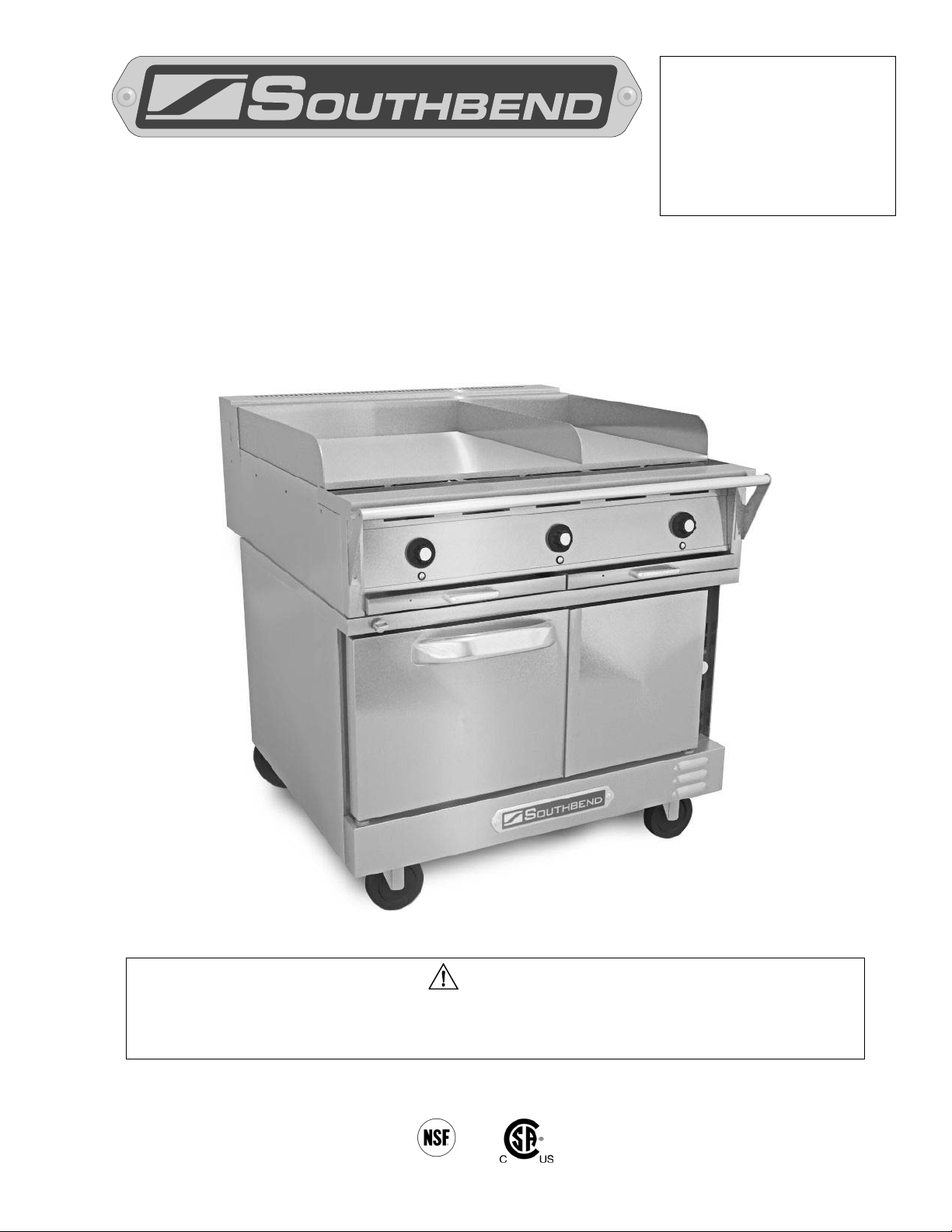
OVEN RANGE
Improper installation, adjustment, alteration, service or maintenance can cause property damage,
IMPORTANT FOR FUTURE REFERENCE
Please compl ete this information and retain this
manual for the l ife of the equi pment:
Range-Top Model #: __________________
Range-Top Serial #: __________________
Oven-Base Model #: __________________
Oven-Base Serial #: __________________
Date Purchased: ____________________
OWNER’S MANUAL
Wendy’s Electr i c Ra nge
Range-Top Model SE36N-TTT, Oven-Base Model TVES/10WC
WARNING
injury or death. Read the installation, operating and maintenance instructions thoroughly before
installing or servicing this equipment.
MANUAL 1195746 (05/12)
$30.00
1100 Old Honeycutt Road, Fuquay Varina, NC 27526 USA
www.southbendnc.com
MANUAL SECTION CO
Page 2
WENDY’S ELECTRIC RANGE
death.
injury, product damage, or property damage.
understood, even though not dangerous.
SAFETY PRECAUTIONS
Before installing and operating this equipment, be sur e everyone involved in its operation is fully trained
and aware of precautio ns. Accidents and problems can be ca used by failure to follow fundam ental rules
and precautions.
The following symbols , found throughout this m anual, alert you to potentiall y dangerous conditions to t he
operator, service personnel, or to the equipment.
DANGER
WARNING
CAUTION
NOTICE
This symbol warns of immediate hazards which will result in severe injury or
This symbol refers to a pot ential hazard or unsaf e practice which could resu lt in
injury or death.
This symbol refers to a pot ential hazard or unsaf e practice which could resu lt in
This symbol refers to information that needs special attention or must be fully
WARNING
FIRE H AZARD
FOR YOUR SAFETY
Do not store or use gasoline or other flamm able vapors and liquids in the vicinit y of this or an y other
appliance.
Keep area around appliances free and clear of combustibles.
Purchaser of equipm ent must post in a prominent loc ation detailed instr uctions to be fol lowed in the
event the operator smells smoke. Obtain the instructions from the local electrician/installer.
NOTICE
Be sure this Owner’s Manual and important papers are given to the proper authority to retain for
future reference.
NOTICE
This product is intended for commercial use only. NOT FOR HOUSEHOLD USE.
Copyright © 2012 by Southbend. All rights reserved. Published in the United States of America.
PAGE 2 OWNER’S MANUAL 1195746
Page 3
WENDY’S ELECTRIC RANGE TABLE OF CONTENTS
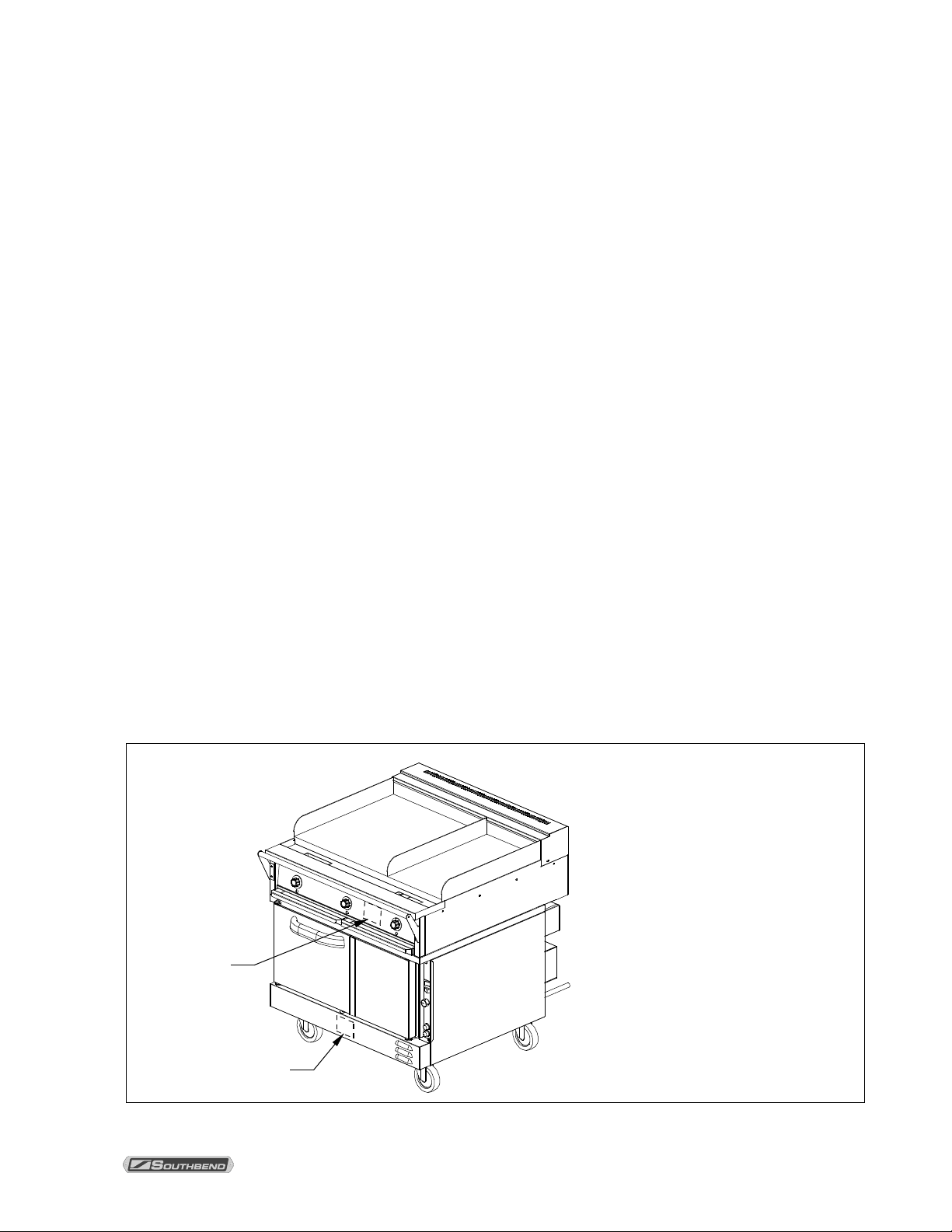
Range-Top
Serial Plate
(inside panel)
Oven-Base Serial Plate
(inside panel)
Congratulations! You have purchased one of the finest pieces of heavy-duty commercial cooking
equipment on the market.
You will find that your n e w equ ipment, like all Southbe nd e qu ipment, has been de signe d a nd manufactured
to meet the toughest stand ards in the i ndustr y. Each piec e of S outhbe nd equipm ent is c arefull y engineer ed
and designs are verified through laboratory tests and field installations. With proper care and field
maintenance, you will experience years of reliable, trouble-free operation. For best results, read this
manual carefully.
RETAIN THIS MANUAL FOR FUTURE REFERENCE.
Table of Contents
Description .............................................................................................................................. 4
Specifications ......................................................................................................................... 5
Installation .............................................................................................................................. 9
Operation .............................................................................................................................. 19
Cooking Hints (Oven) ........................................................................................................... 23
Cleaning ............................................................................................................................... 25
Adjustments .......................................................................................................................... 28
Troubleshooting .................................................................................................................... 36
Read these instructions carefully before attempting installation. Installation and initial startup should be
performed by a qualified installer. Unless the installation instructions for this product are followed by a
qualified service tech nic i an (a per s on exper i enced in and knowledgeable with the insta lla tio n of c om mercial
gas and/or electric cooking equipment) then the terms and conditions on the Manufacturer’s Limited
Warranty will be rendered void and no warranty of any kind shall apply.
In the event you have questions concerning the installation, use, care, or service of the product, contact:
Southbend Technical Service
1100 Old Honeycutt Road
Fuquay Varina, North Carolina 27526 USA
www.southbendnc.com
The range-top serial plate is located on t he interior side of the top front panel, while t he oven-base serial
plate is located on the interior side of the lower front panel, as shown below.
It is the responsibility of the owner to
have accurate information regarding unit
Serial & Model Numbers when
contacting Southbend regarding
questions on a specific unit.
It is STRONGLY SUGGESTED that this
information to be copied from the unit
(or from the shipping-container labels)
into this manual and/or in a secure place
for future reference.
Because of unforeseen circumstances
and the working environment of the unit,
the serial plates may become difficult to
read over time.
Range-Top Model #: _____________________
Range-Top Serial #: ______________________
Oven-Base Model #: _____________________
Oven-Base Serial #: ______________________
OWNER’S MANUAL 1195746 PAGE 3
Page 4

DESCRIPTION WENDY’S ELECTRIC RANGE
DESCRIPTION
DESCRIPTION
The Wendy’s Electric Range consists of a split electric griddle top (model SE36N-TTT) attached to a
convection oven bas e (model TVES/10WC). T he Range can b e ordered with various electrical conn ection
options including 208, 240, 380, 4 15, or 480 volts at 50 or 60 hertz. The oven base is 1-phase, while the
range top is 3-phase. See the Installation section of this manual for specific information.
Operating power must be supplied via either a fused disconnect switch or a circuit breaker, sized in
compliance with the local gov erning electrical codes, or in the absence of local codes, with the National
Electrical Code, ANSI/NFPA 70 or the Canadian Electrical Code, CSA C22.2, as applicable.
OVEN BASE
The oven base is a Southbend m odel TVES/10WC electric range convection oven that is rated h eavy dut y
for commercial use. T he heatin g elem ent is locate d behind th e air baff le in the ov en chamber . An impellertype blower fan dr aws air in and circu lates it across the h eating elements to tra nsfer the heat to the food
product being cooked or baked. Standard features of the oven base include:
• Oven 7.5 kW
• Solid, 60/40-split, dependent doors
• Stainless steel interior
• Soft Air, one-speed, 1/2 hp fan motor
• Four-position, removable rack guides with three standard, chrome-plated racks and one divided
rack (stainless steel racks are an option)
• Cool-down fan mode
• Oven “ready” light
• Three-position oven thermostat: Low 325°F (163°C), M edium 335°F(168°C), and High 375°F
(191°C)
• Optional casters with cable restraint kit
• Optional 72" (1829mm) NEMA 6-50P cord and plug
RANGE TOP
The range top is a Southbend Model SE36N-TTT 36" (914mm) wide sp lit griddle with separ ate 23"×24"
(584mm×610mm) and 13"×24" (330mm×610mm) cooking areas, and featuring three separate
thermostatically contro lled cooking regions. Each therm ostat has a temperature range of 250°F to 850°F
(121°C to 454°C). Standard features of the range top include:
• Heavy-duty griddle plate with divider and side-and-rear splash guards
• Front rail with belly bar
• Aluminized-steel frame with stainless-steel front, sides, and rear
• “Insta-On” thermostatic control of griddle surface temperature: 250°F to 850°F (121°C to 454°C)
• Optional 72" (1829mm) NEMA 15-60P cord and plug
PAGE 4 OWNER’S MANUAL 1195746
Page 5
WENDY’S ELECTRIC RANGE SPECIFICATIONS
SPECIFICATIONS
Nominal Amperes per Line-Wire
Minimum Supply
L1-L2
L2-L3
L1-L3
L1
L2
L3
3-Phase
1-Phase
Heating Elements
7.50
2.50
2.50
2.50
10.4
10.4
10.4
18.1
Motor & Controls
0.90
0.00
L1-N
0.90
0.0
0.0
4.1
4.1
Heating Elements
7.50
2.50
2.50
2.50
18.0
18.0
18.0
31.3
Motor & Controls
0.90
0.00
0.00
0.90
4.1
0.0
4.1
4.1
Heating Elements
7.50
2.50
2.50
2.50
21.0
21.0
21.0
36.1
SPECIFICATIONS
NOTICE
The appliance, when instal led, m us t be electricall y grounde d in accor danc e with local c odes, or in the
absence of local codes , with the Nationa l Electrical C ode, ANSI/NF PA 70, or the Canadian Electr ical
Code, CSA C22.2, as applicable.
Southbend reserves the right to change specifications and product design without notice. Such
revisions do not entit le the buyer to c orres pond ing cha nges, a dditi ons, or r eplace m ents for previousl y
purchased equipment.
This product is intended for commercial use only, not for household use.
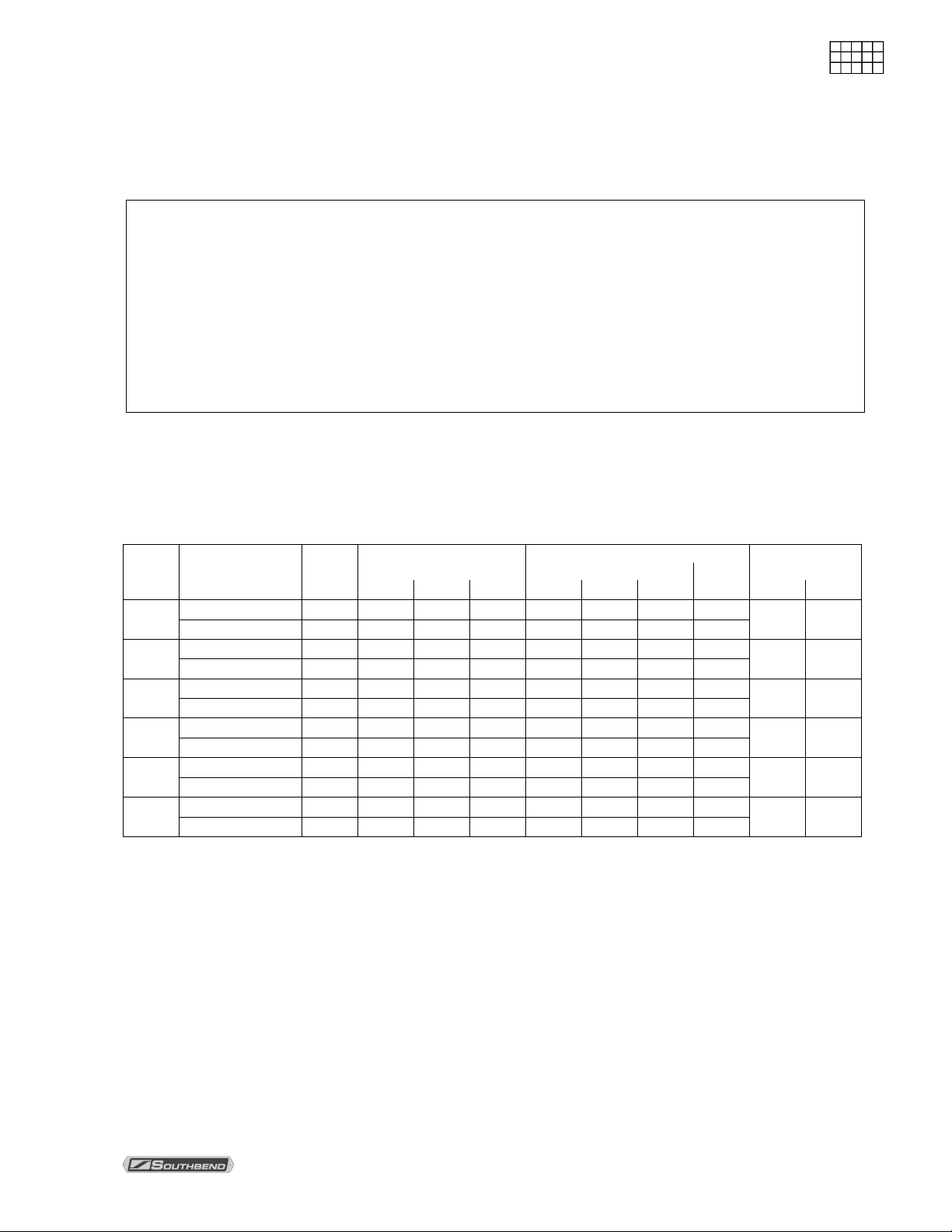
ELECTRICITY SUPPLY
The electrical connections for th e oven base and the range top are made separately.
Use 167°F (75°C) wire for all supply lines.
The following table lists the electricity supply requirements for the oven base.
Supply
Voltage
480
415
380
240
220
(50Hz)
208
Oven Component
Heating Elements 7.50 2.50 2.50 2.50 9.0 9.0 9.0 16.0
Motor & Controls 0.90 0.00 0.00 0.90 2.2 0.0 2.2 2.2
Motor & Controls 0.90 0.00 L1-N 0.90 0.0 0.0 3.8 3.8
Heating Elements 7.50 2.50 2.50 2.50 11.4 11.4 11.4 20.0
Motor & Controls 0.90 0.00 0.00 0.90 3.8 0.0 3.8 3.8
Heating Elements 7.50 2.50 2.50 2.50 19.7 19.7 19.7 34.1
Motor & Controls 0.90 0.00 0.00 0.90 4.3 0.0 4.3 4.3
Total
3-Phase Loading (kW/phase)
kW
3-Phase
1-Phase
Total
Wire (AWG) Size
14 10
12 10
12 8
10 8
10 8
8 8
An electrical diagram is located on the side of the control panel assembly (see drawing on page 37).
Electrical diagrams can also be found in this manual beginning on page 38.
The electrical connect ions for the o ven base are made directly to a terminal block that is locate d inside the
control-panel com partment on the back-right side of the oven. A circular ope ning sized for a strain-relief
fitting is located on the back of the oven near the right side (right as seen fr om the front of the oven, see
drawing on page 16).
The oven base is shipped wired for single-phase. If necessary, the oven base c an be field-converted to
three-phase power (see page 34).
OWNER’S MANUAL 1195746 PAGE 5
Page 6
SPECIFICATIONS WENDY’S ELECTRIC RANGE
SPECIFICATIONS
L1-L2
L2-L3
L1-L3
L1
L2
L3 480
24.2
5.3
5.3
5.3
19.1
19.1
19.1
8
240
24.2
5.3
5.3
5.3
38.2
38.2
38.2
4
220 (50Hz)
24.2
5.3
5.3
5.3
41.7
41.7
41.7
4
The following table lists the electricity supply requirements for the range top.
Supply
Voltage
415 24.2 5.3 5.3 5.3 22.1 22.1 22.1 6
380 24.2 5.3 5.3 5.3 22.1 22.1 22.1 6
208 23.9 5.2 5.2 5.2 43.3 43.3 43.3 4
3-Phase Loading (kW/phase) Nominal Amperes per Line-Wire
Total
kW
Minimum Supply
Wire (AWG) Size
The electrical connections for the range top are made directly to a terminal block that is located on the
back-right side of the range top, behind an access panel. A circular opening sized for a strain-relief fitting is
located next to the access panel (see drawing on page 16).
MINIMUM CLEARANCES
WARNING
There must be adequate clearance between the unit and combustible construction.
Minimum Clearance from Minimum Clearance from
Combustible Construction Other Components
Back 2" (51mm) 2" (51mm)
Right Side 3" (76mm) 6" (152mm)
Left Side 3" (76mm) 6" (152mm)
Floor 0" 0"
Adequate clearance m ust be provided in the aisle in front of the unit to permit operation (including
opening of doors, the oven racks, and the grease drawers), as well as for servicing.
There must be a minimum clearance of 2" (51mm) between the motor on the back and noncombustible constr uction. C are must be tak en to prov ide adequ ate air c irculati on to pre vent the m otor
from overheating.
Do not locate the oven adjac ent to any high heat or grease-producing piece of equipm ent, such as a
range top, griddle, fr yer, etc., that could allow radiant heat to raise t he ex teri or tem per ature of the oven
above 130°F (54°C). DO NOT MOUNT ABOVE OTHER COOKING EQUIPMENT.
PAGE 6 OWNER’S MANUAL 1195746
Page 7
WENDY’S ELECTRIC RANGE SPECIFICATIONS
SPECIFICATIONS
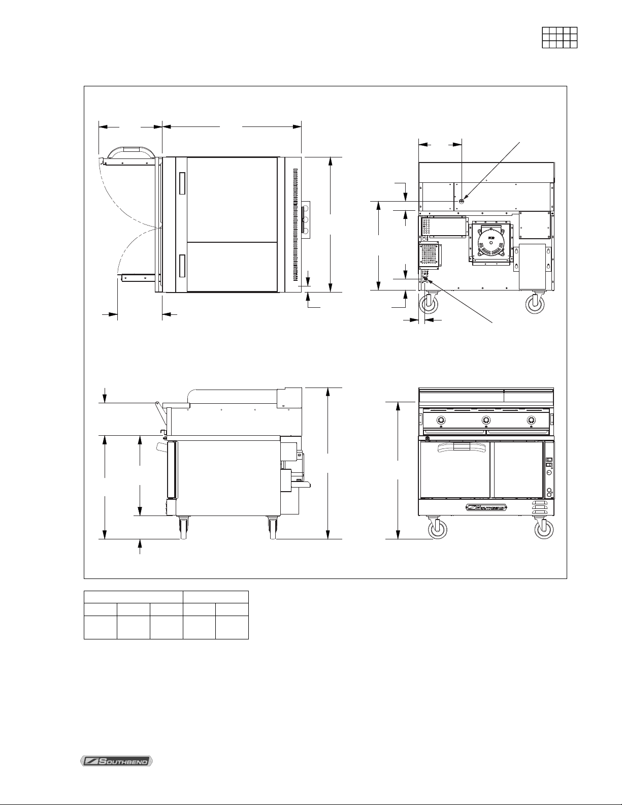
Dimensions are s hown in inches and (millimeters)
EXTERIOR DIMENSIONS
8.7
(221)
17.0
(432)
12.0
(303)
37.0
(940)
TOP VIEW
11.4
(288)
2.4 (62)
36.0
(914)
23.6
(600)
1.6 (41)
3.0 (75)
1.7 (44)
Range-Top
Electr ical Connection
Oven-Base
Electr ical Connection
REAR VIEW
27.5
(698)
21.2
(539)
6.3
(159)
40.4
(1025)
SIDE VIEW FRONT VIEW
36.5
(927)
Oven Interior Rack Clearance
width depth height width depth
29"
(737)
21.5"
(546)
14"
(356)
28.19"
(716)
21"
(533)
OWNER’S MANUAL 1195746 PAGE 7
Page 8

SPECIFICATIONS WENDY’S ELECTRIC RANGE
SPECIFICATIONS
VENTILATION
NOTICE
Proper ventilation is the owner’s responsibility. Any problem due to improper ventilation will not be
covered by the warranty.
The Southbend warranty does not require that a Wendy’s Electric Range be installed under a ventilation
canopy. However, local codes may require installation under a ventilation canopy.
If a ventilation canopy is used, it is recommended that a canopy extend 6" (152mm) past the appliance and
that the bottom edge be located 6'6" (1981mm) from the floor. Filters should be installed at an angle of 45°
or more from the horizontal. This position prevents dripping grease and facilitates collecting the run-off
grease in a drip pan, unusually installed with a filter.
If an exhaust fan is used, it should be installed at least 2" (51mm) above the rear of the unit. A strong
exhaust fan tends to create a vacuum in the room. In case of unsatisfactory performance on any
appliance, check the appliance with the exhaust fan in the OFF position. This should be done only long
enough to check equipm ent performance. T hen turn the exhaust fan back on and let it run to remove any
exhaust that may have accumulated during the test.
PAGE 8 OWNER’S MANUAL 1195746
Page 9

WENDY’S ELECTRIC RANGE INSTALLATION
INSTALLATION
INSTALLATION
NOTICE
These installation procedures must be followed by qualified personnel or warranty will be void.
Local codes regarding ins tallation var y greatl y from one area to anot her. The Nati onal Fire Protectio n
Association, Inc. states in its NFPA 96 latest edition that local codes are the “authority having
jurisdiction” when it com es to installation requirem ents for equipment. T herefore, installations should
comply with all local codes.
The appliance, when instal led, m us t be electricall y grounde d in accor danc e with local c odes, or in the
absence of local codes , with the Nationa l Electrical C ode, ANSI/NF PA 70, or the Canadian Electr ical
Code, CSA C22.2, as applicable.
Step 1: Unpacking
IMMEDIATELY INSPECT FOR SHIPPING DAMAGE
All containers should be examined for damage before and during unloading. The freight carrier has
assumed responsibility for its safe transit and delivery. If damaged equipment is received, either
apparent or concealed, a claim must be made with the delivering carrier.
Apparent damage or loss m ust be noted on the fr eight b ill at the t ime of de livery. T he f reight bill m us t
then be signed by the carrier representative (D river). If the bill is not signe d, the carrier may refuse
the claim. The carrier can supply the necessary forms.
A request for inspect ion must be m ade to the carrier within 15 da ys if there is c oncealed dam age or
loss that is not apparent until after the equipment is uncrated. The carrier should arrange an
inspection. Be certain to hold all contents plus all packing material.
1. Cut banding straps and remove packing material.
2. Remove tie-down strap holding range to wooden skid.
OWNER’S MANUAL 1195746 PAGE 9
Page 10
INSTALLATION WENDY’S ELECTRIC RANGE
INSTALLATION
DO NOT REST THE UNIT ON ITS FRONT, SIDES, OR BACK. THIS CAN CAUSE PERMANENT
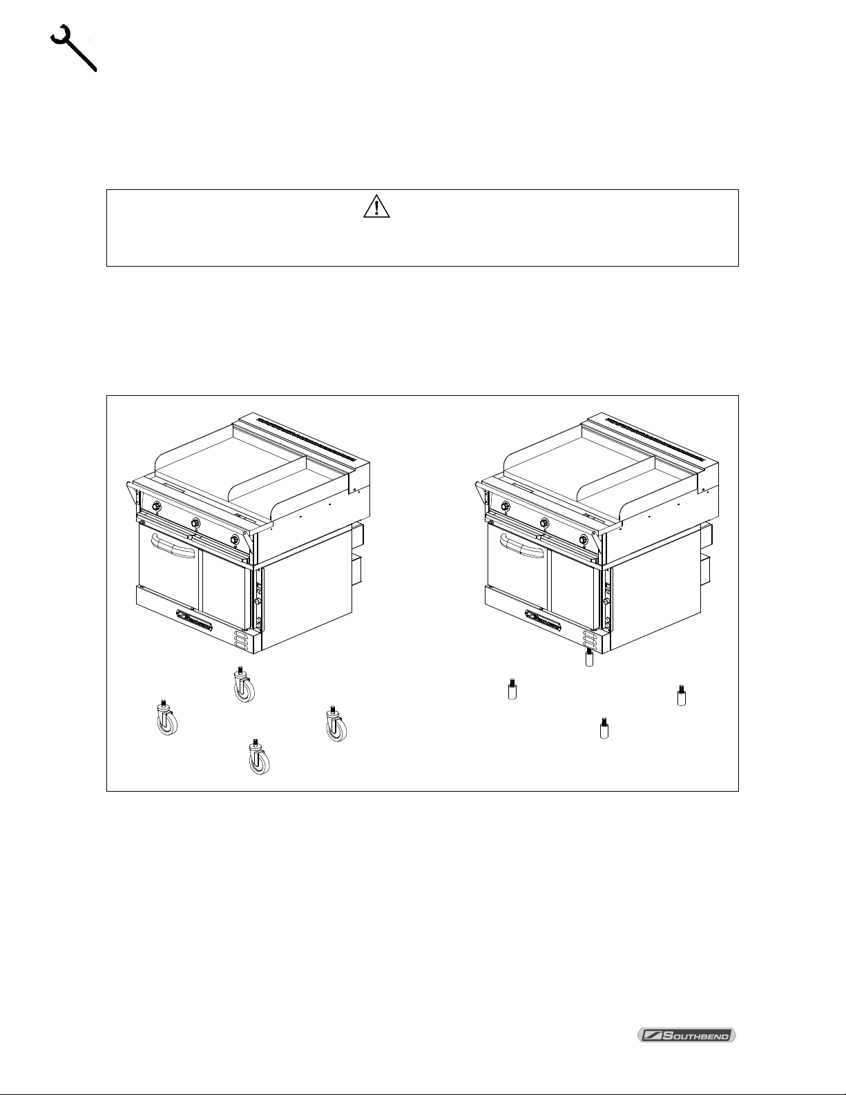
Step 2: Installation of Legs or Casters on Oven Base
1. Raise oven sufficiently to allow c learance for the legs or cas ters to be attached. Use of a lift tr uck or
other mechanical lif ting means is recom mended. For safety, “shor e up” and support the oven with an
adequate blocking arrangement strong enough to support the load.
WARNING
DAMAGE TO THE UNIT AND WILL VOID THE WARRANTY.
2. Screw into the bottom of eac h corner of the unit either an adjustable leg or a caster (dep ending on
which option was ord ered). If attaching casters, the tw o casters with br akes should be a ttached to the
front corners.
3. Lower the unit gently onto a level surface. Never drop or allow the unit to fall.
4. Use a level to make sure that th e unit is level. T he adj ustable legs can be sc rewed in or ou t to lower or
raise each corner of the oven.
5. If casters were installed, go to Installation Step 3 on the next page; otherwise go to Step 4 on page 12.
PAGE 10 OWNER’S MANUAL 1195746
Page 11
WENDY’S ELECTRIC RANGE INSTALLATION
INSTALLATION
E
D
A
C
B
G
F
I
H
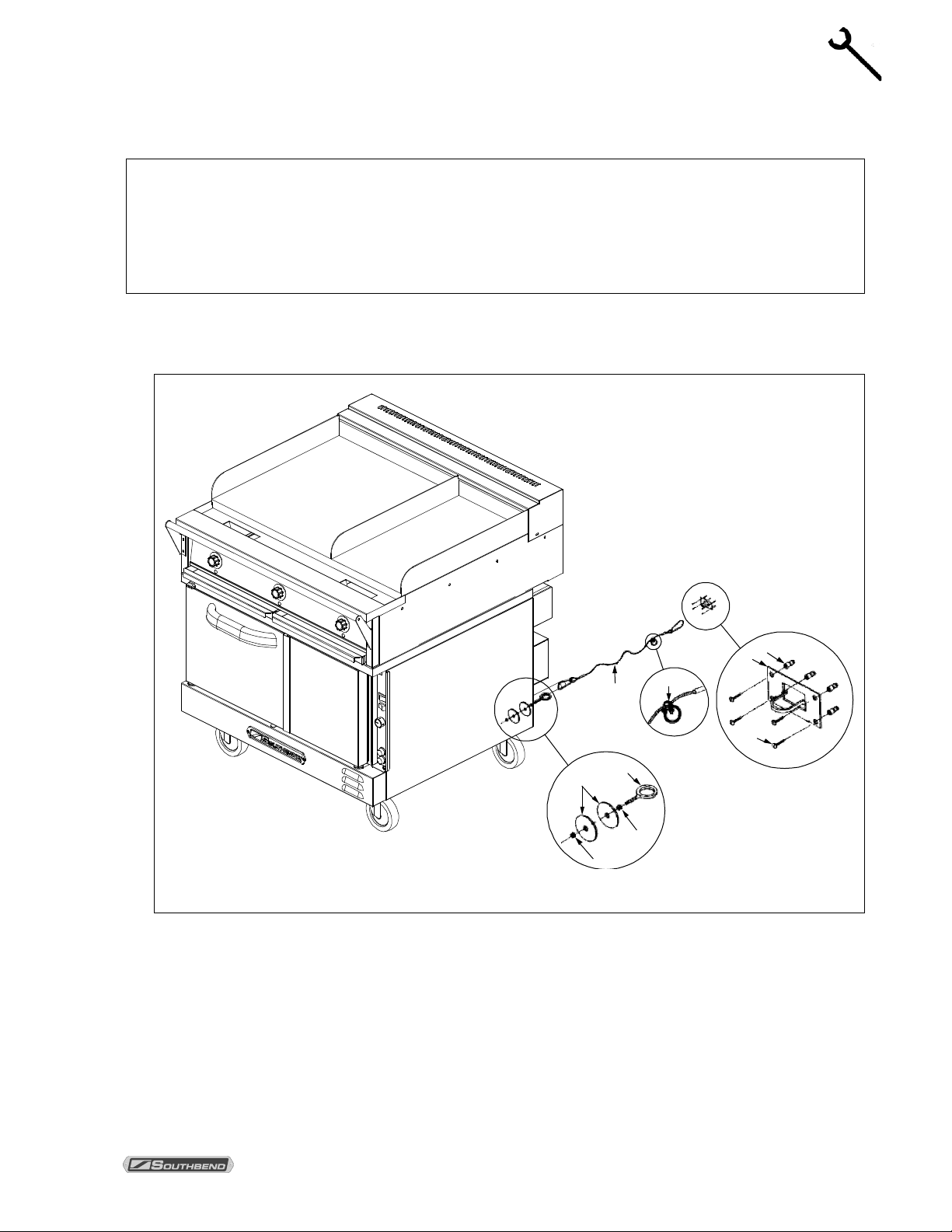
Step 3: Installation of Rest r aint (Only for Units with Casters)
All units ordered with casters are supplied with a restraint kit.
NOTICE
For an appliance equipp ed with casters adequate m eans must be provided to limit the movement of
the appliance without depending on, or transmitting stress to, the electric conduit. The restraining
means should be att ached to a fram e member on the bac k of the unit , and the appliance should be
installed using a flexible conduit.
1. Secure the restraining-device bracket (item “B” in the following illustration) to a wall stud located as
close as possible to the ap pliance connector inl et and outlet connectio ns. Use four #12 scre ws (items
“C”) and plastic anchors (items “A”) if necessary.
Note: Kit can be purchased from Southbend (part number 1176867).
2. Install eye-bolt (item “F”) to a frame member on the rear of the equipment. After checking carefully
behind the frame member for adequate clearance, drill a 1/4" (6mm) hole through the frame member.
3. Thread hex nut (item “G”) and slide the was her (item “H”) onto the e ye-bolt. Ins ert the e ye-bolt through
the 1/4" (6mm) drilled hole and secure with a washer (item “H”) and nylon lock nut (item “I”).
4. Using the spring-loaded snap hooks, attach the restraining device to the bracket and the eye-bolt.
5. Using the cable clamp (item “D” ), adj us t the r estr ain in g de vic e ext end ed len gth t o preve nt o ver -bending
or kinking of the appliance connector.
Be sure all controls are turned off prior to disconnecting. After reconnecting, be sure that the range is
switched OFF.
OWNER’S MANUAL 1195746 PAGE 11
Page 12
INSTALLATION WENDY’S ELECTRIC RANGE
INSTALLATION
Step 4: Connect Electricity to Oven Base
WARNING
ELECTRIC GROUNDING INSTRUCTIONS
This appliance, when inst al led, must be electrically grounded in acc or da nc e with l ocal c odes, or in th e
absence of local codes, wit h the National Electrical C ode, ANSI/NFPA 70 or the Canad ian Electrical
Code, CSA C22.2, latest editions, as applicable.
WARNING
INSTALLATION AND SERVICE WORK MAY BE PERFORMED ONLY BY A QUALIFIED
ELECTRICIAN O R TECHNICIAN WHO IS EXPERIEN CED IN, AND KNOWLEDGEABLE WITH, THE
OPERATION OF COMMERCIAL COOKING EQUIPMENT.
NOTICE
For an appliance equipp ed with casters adequate m eans must be provided to limit the movement of
the appliance without depending on, or transmitting stress to, the electric conduit. The restraining
means should be att ached to a fram e member on the bac k of the unit , and the applianc e should be
installed using a flexible conduit.
NOTICE
The electrical connections for the oven base and for the range top are made separately.
The oven base requires a 1-phase connection, but can be field-converted to use a 3-phase
connection (see page 34).
Local and/or national electric codes supersede any instructions or illustrations in this manual.
The wiring diagram for the oven base is located on the side of the oven control panel assem bly ( see page
37). Wiring dia grams are also printed in th is m anual (beginning o n page 38). Be sure that the in put voltage
and phase match the re quirements shown on th e oven-base serial plate, which is located inside the lower
front panel (see drawing on page 3).
The unit must be adequately grounded. Use 167°F (75°C) wire for all supply lines.
The optional (6/3) cable assembly supplied with the oven base (1-phase ONLY), should only be installed by
a licensed electrician or qualified service technician to ens ure compliance with all electrical co des at the
installation location.
1. CHECK THAT THE POWER SUPPLY CIRCUIT BREAKER IS OPEN.
2. Locate and remove the four screws that secure the lower f ront panel (item s “A” in the drawing on page
13). Lift up the panel and pull it forward to remove it, then set it aside.
3. Locate and remove the five screws (3 bac k, 2 front) that secure th e right side pane l of the oven base.
Remove and set aside the side panel and insulation.
4. Route the supply wires and the grou nding wire through th e hole on the back of the oven base. Use a
strain-relief fitting.
5. Attach each supply wire to the appropr iate term inal of the term inal bloc k (acc ording to t he appropr iatevoltage/phase wiring diagr am found in this m anual starting on page 38), taking c are not to disconnect
any wires that may already be connected to the terminal block.
PAGE 12 OWNER’S MANUAL 1195746
Page 13
WENDY’S ELECTRIC RANGE INSTALLATION
INSTALLATION
Oven Base Electrical Connection
Contactor
Hole
Grounding Lug
A
Terminal Block
6. Insert the ground wire into the grounding lug and tighten the screw.
7. Check that all connections match the wiring diagram and are tight.
8. Reattach the right-side panel of the oven base and insulation, and the lower-front panel.
OWNER’S MANUAL 1195746 PAGE 13
Page 14
INSTALLATION WENDY’S ELECTRIC RANGE
INSTALLATION
Oven-Base Connection Using Power Cord (208/240V and 480V, 1-Phase ONLY)
WARNING
INSTALLATION AND SERVICE WORK MAY BE PERFORMED ONLY BY A QUALIFIED
ELECTRICIAN O R TECHNICIAN WHO IS EXPERIEN CED IN, AND KNOWLEDGEABLE WITH, THE
OPERATION OF COMMERCIAL COOKING EQUIPMENT.
NOTICE
For an appliance equipp ed with casters adequate m eans must be provided to limit the movement of
the appliance without depending on, or transmitting stress to, the electric conduit. The restraining
means should be att ached to a fram e member on the bac k of the unit , and the appliance should be
installed using a flexible conduit.
Local and/or national electric codes supersede any instructions or illustrations in this manual.
1. CHECK THAT THE POWER SUPPLY CIRCUIT BREAKER IS OPEN.
2. Locate and remove the four screws that secure the lower f ront panel (item s “A” in the drawing on pag e
13). Lift up the panel and pull it forward to remove it, then set it aside.
3. Locate and remove the five screws (3 bac k, 2 front) that secure th e right side pane l of the oven base.
Remove and set aside the side panel and insulation.
4. Route the supply wires and the grounding wire through the hole on the back of the oven base, as
shown in the illustration belo w. Use a strain-relief fitting.
Oven Base Electrical Connection Using Power Cord
(Shown with right side panel removed.)
PAGE 14 OWNER’S MANUAL 1195746
Page 15

WENDY’S ELECTRIC RANGE INSTALLATION
INSTALLATION
5. Attach cable conductors to indicated terminals, as shown, using an “APPROVED” three-conductor
cable (1-phase ONLY). Tighten all cable clamps securely.
BLACK – L1
WHITE – L3
GREEN – GND. LUG
(For conversion to a 3-phase connection, see page 34.)
6. Check that all connections match the wiring diagram and are tight.
7. Reattach the right-side panel of the oven base and insulation; and the lower-front panel.
Step 5: Connect Electricity to Range Top
WARNING
ELECTRIC GROUNDING INSTRUCTIONS
This appliance, when inst al led, must be electrically grounded in acc or da nc e with l ocal c odes, or in th e
absence of local codes, wit h the National Elec trical Code , ANSI/NFPA 70 or the Canadian Electrical
Code, CSA C22.2, latest editions, as applicable.
WARNING
INSTALLATION AND SERVICE WORK MAY BE PERFORMED ONLY BY A QUALIFIED
ELECTRICIAN O R TECHNICIAN WHO IS EXPERIEN CED IN, AND KNOWLEDGEABLE WITH, THE
OPERATION OF COMMERCIAL COO KIN G EQ UI PMENT.
NOTICE
For an appliance equipp ed with casters adequate m eans must be provided to limit the movement of
the appliance without depending on, or transmitting stress to, the electric conduit. The restraining
means should be att ached to a fram e member on the back of the unit , and the appliance should be
installed using a flexible conduit.
NOTICE
The electrical connections for the oven base and for the range top are made separately.
The range top requires a 3-phase connection.
Local and/or national electric codes supersede any instructions or illustrations in this manual.
The wiring diagram for the range top is located on the interior side of the rear access panel (see drawing on
page 16). W iring diagrams are also print ed in this manual (be ginning on page 38). Be sure that the input
voltage and phase match the requirements shown on the serial plate, which is located inside the upper
front panel (see drawing on page 3). When shipped from the factory, the oven base requires 1-phase
power, while the range top requires 3-phase power.
The unit must be adequately grounded. Use 167°F (75°C) wire for all supply lines.
The optional (4/4) cable as sembly supplied with the Range T op (3-Phase ON LY), should on ly be installed
by a licensed elec tricia n or qualif ied ser vice t echn ician to ens ure com pliance with all elec trica l codes at th e
installation location.
OWNER’S MANUAL 1195746 PAGE 15
Page 16

INSTALLATION WENDY’S ELECTRIC RANGE
INSTALLATION
Terminal Block
Grounding Lug
Neutral Terminal Block
(for 380 & 415V Units Only)
Access Panel
Range Top Electrical Connection
1. CHECK THAT THE POWER SUPPLY CIRCUIT BREAKER IS OPEN.
2. Locate and remove the five screws that secure the range-top rear access panel (see the drawing
above), then remove the access panel and set it aside.
3. Route the supply wires and the groundin g wire through the hole on the back of the range top. Use a
strain-relief fitting to secure the cable to the range top.
4. Attach each supply wire to the appropr iate term inal of the term inal block (acc ording to the appropr iatevoltage wiring diagr am found in this manual starting on p age 38), taking care not to disc onnect any
wires that may already be connected to the terminal block.
5. Insert the ground wire into the grounding lug and tighten the screw.
6. The additional terminal block required f or connecting the neutr al wire on a 380V or 415V unit is s hown
in the above drawing. Reference the appropriate wiring diagram starting on page 38.
7. Check that all connections match the wiring diagram and are tight.
8. Ensure that the cable clamp has been secured onto the rear of the range top and tightened on the
cable.
9. Reattach the range-top rear access panel.
PAGE 16 OWNER’S MANUAL 1195746
Page 17

WENDY’S ELECTRIC RANGE INSTALLATION
INSTALLATION
Range-Top Connection Using Power Cord (208/240V and 480V, 3-Phase ONLY)
WARNING
INSTALLATION AND SERVICE WORK MAY BE PERFORMED ONLY BY A QUALIFIED
ELECTRICIAN O R TECHNICIAN WHO IS EXPERIEN CED IN, AND KNOWLEDGEABLE WITH, THE
OPERATION OF COMMERCIAL COOKING EQUIPMENT.
NOTICE
For an appliance equipp ed with casters adequate m eans must be provided to limit the movem ent of
the appliance without depending on, or transmitting stress to, the electric conduit. The restraining
means should be att ached to a fram e member on the bac k of the unit , and the appliance should be
installed using a flexible conduit.
Local and/or national electric codes supersede any instruc tions or illustrations in this manual.
1. CHECK THAT THE POWER SUPPLY CIRCUIT BREAKER IS OPEN.
2. Locate and remove the five s crews that secur e the range-top rear acc ess panel ( see drawing on p age
16), then remove the access panel and set it aside .
3. Route the supply wires and the groundin g wire through the hole on the back of the range top. Use a
strain-relief fitting to secure the cable to the range top.
4. Attach cable conductors to terminal block, as shown in the illustration on the next page, using an
“APPROVED” NEMA 15-60P cord and plug. Tighten all cable clamps securely.
BLACK – L1 (X)
WHITE – L2 (Y)
RED – L3 (Z)
GREEN – GND. LUG
5. Check that all connections match the wiring diagram and are tight.
6. Ensure that the cable clamp has been secured onto the rear of the range top and tightened on the
cable.
7. Reattach the range-top rear access panel.
Step 6: Check the Installation
Check the installation, as follows:
1. Check that all screws and bolts are tightened.
2. Check electrical connections, including proper grounding.
3. Move the unit into the final position at which it will be operated.
4. For units with casters, check that the restraint has been properly installed and is connected.
5. Check that the unit is level. If not, adjust the legs or casters.
6. Check that the appropriate minimum clearances are satisfied (see page 6).
7. Check that there is sufficient clearance to open oven doors, and to pull out oven racks and grease
drawers.
OWNER’S MANUAL 1195746 PAGE 17
Page 18

INSTALLATION WENDY’S ELECTRIC RANGE
INSTALLATION
Step 7: Initial Cleaning of the Range Top
1. Remove the rust preventative mater ial from the entire s urface of the range top us ing a non-flammable
grease solvent.
2. Clean the entire griddle surfac e by wiping it with a clean cloth d ampened with war m water and a mild
detergent.
3. Rinse the surface by wiping it with a clean, damp cloth. Wipe dry.
4. “SEASON” the entire griddle before proceeding (see procedure on page 20 of this manual).
Step 8: Check Operation of the Unit
Check the operation of the range top, as follows:
1. AFTER SEASONING the griddle surf ace, check that all range-top and oven-ba se controls are set to
the OFF position.
2. Verify the electricity supply to the unit is turned on.
3. Check each griddle zone one at a time starting from the left side. Confirm that each griddle zone begins
heating, then turn the control for that zone to OFF.
4. Repeat step 3 for each zone of the griddle.
Check the operation of the oven base, as follows:
5. Set the oven temperature control to LOW.
6. Switch the POWER switch located on the Oven Control Panel to ON.
7. After a few minutes, open the door of the oven and confirm that the oven is heating.
8. Switch OFF all range and oven controls.
Step 9: Wipe Clean and Shut-Down Range
Complete the installation by leaving the unit ready for customer use:
1. Turn-off all power controls and allow unit to cool.
2. Wipe clean all surfaces.
3. Unless the unit is to be placed in service immediately, shut off the electricity.
4. Make sure that a copy of this manual will be available to the people who will operate and maintain the
unit.
.
PAGE 18 OWNER’S MANUAL 1195746
Page 19

WENDY’S ELECTRIC RANGE OPERATION
OPERATION
Power Indicator
Grease Drawers
Temperature
Control Knob
(OFF, temperature)
Grease Trough
OPERATION
NOTICE
Do NOT cook on a griddle before “seasoning” it each day (as described later in this section).
OPERATON OF RANGE TOP
The Range Top is t herm ostatica ll y control led. Each 12" (30 5mm ) wid e griddle zone has a control knob tha t
can be turned to OFF, or to any temperature in the range 250°F to 850°F (121°C to 454°C).
To start cooking, turn on the appropriate control knob(s) to the desired temperature(s).
Never leave utensils on the griddle.
Do not abuse the equipment by leaving t he thermostat at a high temperature all the time. During idling
periods, turn the t hermostat to a low temperature to keep the griddle warm. (D o not allow the griddle to
overheat above 850°F (454°C), as this will cause warping or breakage.) W hen necessary while cooking,
pull out and empty the grease drawers.
When done cooking, turn the appropriate control knob to OFF.
Cleaning instructions begin on page 25 of this manual.
Temperature Control Knob – Each knob controls the corresponding zone of the griddle surface. Each
knob can be
turned to OFF, or to any temperature in the range 250°F to 850°F (121°C to 454°C).
Power Indicator – The indicator glows amber when the corr esponding gr idd le zone is being h eated. When
the setting temperatur e is reached, the indicator will turn off, then blink on-and-off as the temperature is
held steady.
Grease Trough – Two chutes located at the front of the gri ddle surface provide drainag e into the grease
drawers.
Grease Drawers – Conta iners f or grease drain ing through t he greas e chutes f rom greas e trough. Pull out
to empty and clean.
OWNER’S MANUAL 1195746 PAGE 19
Page 20

OPERATION WENDY’S ELECTRIC RANGE
OPERATION
NEVER TOUCH AN OPERATING GRIDDLE. ALWAYS WAIT UNTIL THE TEMPERATURE
SEASONING OF GRIDDLE SURFACE
WARNING
CONTROL KNOBS HAVE BEEN SET TO “OFF” FOR AT LEAST 30 MINUTES.
Griddle should be “seasoned” each day before beginning operations. Do the following:
1. If necessary, clean the griddle surface (see page 25).
2. Spread a light film of unsalted cooking oil over the entire griddle surface with a soft cloth.
3. Set all of the griddle temperature controls to 350°F (175°C).
4. Operate the griddle for at least two m inutes to allow t he oil to w ork into the pores of the m etal, form ing
a smooth coating over the surface of the griddle. Use a spatula to spread the oil, if necessary.
5. Set the griddle controls to O FF and wait at least 30 m inutes for the griddle to cool bef ore wipin g of f the
excess oil with clean cloths.
DAILY OPERATION
1. “Season” the griddle daily before operation (see procedure in preceding subsection of this manual).
2. Set the Temperature Control Knob of each griddle zo ne to the recommended tem perature setting for
the type(s) of food to be heated/cooked.
3. Wait 15 minutes before loading the griddle with food to be sure of heating/cooking the food properly.
4. Observe the indicator below each T emperature Control Knob. Each indicator is lit steadily when the
corresponding zone is h eating to the temperature setting . Each indicator will blink on and off as the
temperature setting is being held almost constant by the thermostatic control.
5. At the end of each day (or shift) clean the griddle as described on page 25 of this manual.
GRIDDLE OPERATING HINTS AND SAFETY TIPS
Never leave the griddle operating without an attendant.
Never place utensils on the griddle.
Do not abuse the equipm ent by leaving the thermostats at a high t emperature all the time. During idlin g
periods, turn the t hermostat to a low temperature to keep the griddle warm. (Do not allow the griddle to
overheat above 850°F (454°C) as this will cause warping or breakage.)
Do not operate the entire griddle at a high temperature when small amounts of food are being
heated/cooked, or during idle periods. Set the Temperature Co ntrol Knob(s) to 200º F (93º C) during idle
periods. Only a few minutes is required to regain the desired operating temperature when food orders
become more frequent. Use only one zone when heating/cooking a small amount of food.
Heat/cook different types of foods at the same time by setting the Temperature Control Knob of each
griddle zone to the temperature for heating/cooking each food type.
“Hold” (keep warm), food in one zone by decreasing the temperature setting.
Use a spatula to remove excess grease or oil into the grease trough after each load of food is
heated/cooked. This reduces the smoking and carbonizing of hot grease.
Pull out and empty the grease drawers when necessary.
When done cooking, turn the appropriate control knob to OFF.
PAGE 20 OWNER’S MANUAL 1195746
Page 21

WENDY’S ELECTRIC RANGE OPERATION
OPERATION
Turning the control knob opens
Locat ion of
OPERATON OF OVEN BASE
WARNING
If the WARNING light turns on, the appliance is m alfunctioning. Turn off or disconnect power f rom
power supply and have the unit serviced by a qualified technician.
The oven-base controls are sho wn in the f igure on the follow ing page of this m anual. To operate t he oven,
do the following:
1. Turn the POWER switch on the oven-base control panel to ON.
2. Switch the FAN MODE switch to COO K. The fan will r un continu ously when the oven doors are close d
(the fan does not cycle o n and off with the heating elements ). If this switch is set to COOL the only
difference is that the fan will continue to run when the oven doors are open.
3. Set the cooking temperature by turning the CO OK TEMPERAT URE contro l un til the indicator m ark on
the knob is pointing at t he desired cook ing temperature (HIG H, MEDIUM, or LO W). The indicator light
near the control knob will be lit while the oven preheats.
4. Wait until the heat-on indicator has gone-out a nd come-on three times . At that time the oven will have
reached the set cooking temperature.
5. Open the oven doors, load the product into the ove n, and close the d oors. When you open the oven
doors, the heating elements and fan will shut off until you close the doors.
6. When the load has finished cook ing, you can rapidl y cool the load b y opening the oven doors (which
will shut off the heat ing elements ) and switching th e FAN MOD E switch to COOL ( which will c ause the
fan to run even though the doors are open).
7. When you are done cooking, turn the COOK T EMPERATUR E control to LOW (full y counterclockwise)
and turn the POWER switch to OFF.
MOISTURE VENT
The oven has a moisture vent that is opened and closed using the s mall knob located near the top lef t
corner of the front of the oven (see i llustration below). Usually the vent is k ept open to allow moisture to
escape. Close the vent (turn the knob clockwise) when doing fine baking.
Moisture Vent
Moisture Vent
Control Knob
or closes moistu re vent (shown
below with its cover removed).
OWNER’S MANUAL 1195746 PAGE 21
Page 22

OPERATION WENDY’S ELECTRIC RANGE
OPERATION
Power Switch
Turn knob to select desired cooking
n indicator will go
temperature.
Fan Mode
uously except when the doors
Heat-On Indicator
Fuses
Warning Light
alfunctions. Turn off or disconnect
Oven Control Panel
OFFON
Switch ON to use the oven, switch
OFF when done using the oven.
POWER
COOLCOOK
FAN MODE
MEDIUM
Cook Temperature Control
In COOK mode, the fan runs
contin
are open. The fan does NOT cycle
with the operation of the heating
elements. In COOL mode, the fan
runs continuously even if the doors
are open. Since the elements will
not operate if the oven doors are
open, to rapidly cool the oven after
cooking is completed, open the
doors and switch the fan mode to
COOL.
temperature (LOW, MEDIUM, or
HIGH). The heat-o
out when the oven reaches the set
temperature, and will cycle on and
off as the elements operate to
maintain the set cooking
PAGE 22 OWNER’S MANUAL 1195746
LOW
COOK TEMPERATURE
HIGH
Indicator is lit when the elements
are operating. It goes out when the
selected temperature is reached.
Indicator is lit if and when unit
m
power from power supply and have
W
A
R
N
I
N
G
the unit serviced by a qualified
technician.
Page 23

WENDY’S ELECTRIC RANGE COOKING HINTS
COOKING HINTS
COOKING HINTS (OVEN)
A convection oven is a different type of oven that offers many features and advantages to food service
operation. The additional capabilities and features of the oven require some learning. However, the
operation of the oven is not difficult to understand or control once you have some practice.
Convection ovens operate much like a standard oven: you turn the oven ON and select a cooking
temperature. An additional control is used to operate the fan (as described on page 19).
In a standard (non-c onvection) oven, the air is relat ively still and an insulating la yer of moistur e surrounds
the cooking food product. In a convection oven, the fan-blown circulating air strips away this insulating layer
allowing the heat to penetrate f aster for q uicker bak ing and roasting. Hence, in a convecti on oven cook ing
procedures and tech niques may require some modific ation for successful results. As a general rule, the
cooking time will be shorter and the cooking temperature will be 25°F to 75°F (14°C to 42 °C) lower than
those called for in recipes for a standard oven.
TIME & TEMPERATURE
Time and temperature ar e important. The best c ooking time and tem perature will depen d on such factor s
as size of load and mixtur e of recipe (par ticularl y moistur e). Onc e an appropr iate tim e and tem perature has
been established for a particular product and load, you will find the result of succeeding loads to be similar.
OVERLOADING
Do NOT overload the oven . The size of the load that can be cook ed satisfactorily depends largely on the
particular product. As a rul e, four racks can be successf ully used for shallo w cakes, cook ies, pies, etc. For
deeper cakes (s uch as angel food), use only three racks because of the size of the pan and the space
required for rising. For ha mburger patties, fis h sticks, cheese sandwic hes, etc., a full com plement of racks
and pans is usually satisfactory.
HELPFUL SUGGESTIONS
Here are some suggestions that will assist in getting the best possible performance from a convection
oven:
• Pre-heat the oven thoroughly before use.
• When re-thermali zing frozen products, pre-heat the o ven to 50°F (28°C) higher than the planned
cooking temperature. After loading, reduce the temperature setting to the appropriate cooking
temperature.
• Space the racks and pans as evenly as possible to allow air circulation.
• Center the load on th e racks to allow f or proper air ci rculation around the s ides. Do not cover the
racks completely with pans.
• Do not use a deep pan for shallow cak es or cookies, etc. A ir circulation acros s the surface of the
product is essential.
WARNING
THE USE OF ALUMINUM FOIL CAN CAUSE HEAT DISTRIBUTION PROBLEMS IN OVENS.
EXTREME CARE MUST BE USED WHEN PL ACING AL UMINUM FOIL IN THE OVEN TO ENSURE
THAT IT DOES NOT BLOCK OR CHANG E THE AIR FLOW . THE USE OF ALUMINU M FOIL MAY
VOID THE PRODUCT WARRANTY IF ITS USE IS ASCERTAINED TO BE A PROBLEM.
OWNER’S MANUAL 1195746 PAGE 23
Page 24

COOKING HINTS WENDY’S ELECTRIC RANGE
COOKING HINTS
COOKING PROBLEMS AND SOLUTIONS
If… then…
Cakes are dark on the sides and not done in the center… lower oven temperature.
Cake edges are too brown… reduce number of pans or lower oven temperature.
Cakes have a light outer color… raise temperature.
Cakes settle slightly in the center… bake longer or raise oven temperature slightly. Do not open
doors except to load or unload product.
Cakes ripple… do not overload pans or use batter that is too thin.
Cakes are too coarse… lower oven temperature.
Pies have uneven color… reduce number of pies per rack or eliminate use of bake pans.
Brown sugar topping or meringue blows off… after oven is preheated, turn off oven and put product in oven
until topping sets, then turn oven back on.
Rolls have uneven color… reduce number or size of pans.
Meats are browned and not done in center… lower oven temperature and roast longer.
Meats are well done and not browned… raise temperature. Limit amount of moisture.
Meats develop hard crust… reduce temperature or place pan of water in oven.
Excessive meat shrinkage occurs… lower oven temperature.
PAGE 24 OWNER’S MANUAL 1195746
Page 25

WENDY’S ELECTRIC RANGE CLEANING
CLEANING
CLEANING
Southbend equipment is sturdily constructed of the best materials and is designed to provide durable
service when treated with ordinary care. To expect the best performance, your equipment must be
maintained in good condit ion and clea ned dai ly. Natura ll y, the periods f or this c are and clean ing depend on
the amount and degree of usage.
Following daily and p eriodic maintenance procedures will e nhance long life for your equipm ent. Climatic
conditions (such as s alt air) ma y require more thorou gh and frequent c leaning or the life of the equ ipment
could be adversely affected .
The oven interior is finished with a porcelain enamel coating. “Spillovers” should be cleaned from the
interior bottom surfac e as soon as p ossibl e to pr event car bonizing and a burnt -on cond ition. Grease or a n y
residue should be cleaned from interior surfaces as soon as it accumulates.
WARNING
FOR YOUR SAFETY, DISCONNECT THE POWER SUPPLY TO THE APPLIANCE BEFORE
CLEANING.
WHEN CLEANING THE BLOWER WHEEL, BE SURE TO HAVE THE POWER SWITCH IN THE
“OFF” POSITION.
WARNING
NEVER TOUCH AN OPERATING GRIDDLE. ALWAYS WAIT UNTIL THE TEMPERATURE
CONTROL KNOBS HAVE BEEN SET TO “OFF” FOR AT LEAST 30 MINUTES.
Clean Areas of Griddle that were used to Cook Food
1. Clean the griddle surface by pushing the greas e and/o r oil into the gr ease tr ough. T hen rub the s urfac e
with a pumice stone or a “griddle stone.” Rub the griddle surface in the direction of the metal grain
while the surface is still warm (NOT hot).
2. Wipe the griddle surface clean of residue from the rubbing stone, using clean cloths.
3. Thoroughly clean the grease troug h, grease c hutes, a nd grease dr awers at l east onc e each da y (more
often if necessary).
4. Allow the griddle to cool. Clean the sides of the griddle and all surfaces surrounding the griddle by
wiping them with a clean cloth dampened in warm water and a mild detergent.
5. Rinse all washed surfaces using a clean clot h dam pened with warm clean water . W ipe dr y with a clean
cloth.
6. Empty each grease drawer as often as necess ary, at least once per shift, and at the en d of each day.
Wash the grease drawers with hot water and a mild detergent. Rinse with clean hot water. Wipe dry.
7. Be sure to replace the grease drawers after each cleaning.
Clean Areas of Griddle that were used to h eat Pots and Cooking Vessels
Areas that have been use d for heating pots or o ther cooking vessels should be cleaned and “seasoned”
prior to cooking/heating any type of food product in that area of the griddle.
8. Allow the griddle section to cool. W ash the entire divided ( 23"×24" or 13"×24") section of the griddle
with warm water and a mild deterg ent. Also, clean all areas near that s ection of the griddle. DO NOT
USE COLD WATER.
OWNER’S MANUAL 1195746 PAGE 25
Page 26

CLEANING WENDY’S ELECTRIC RANGE
CLEANING
9. Rinse the cleaned section of the griddle (and adjacent surfaces) with clean, warm water.
10. Wipe dry with clean cloths.
11. “Season” the cleaned griddle section according to the procedure on page 20 of this manual.
Clean Oven
12. Turn the POWER switch to OFF and allow the oven to cool.
13. Remove the oven-interior rac ks and r ack slide fr am es. (T he rack slide fr am es are readil y rem ovable by
merely raising to disengag e them from their sockets.) W ash the racks and rack slides i n a sink with
mild detergent and warm water. Dry them thoroughly with a clean cloth.
14. Look to see if any foreign matter has accumulated o n the blades of the blower wheel (which wil l re duc e
air circulation). If nec essar y, rem ove the re ar lini ng of t he o ven, wh ich is sec ured b y thumbs crews near
each corner. Use a stiff brush to remove accumulations f rom the blower blades, then wash w ith soap
and water.
15. Wash the interior surfaces with mild detergent and warm water. Rinse with clean water, and dry
thoroughly with a clean cloth. For stubborn accumulations, a commercial oven cleaner may be used.
16. Clean the control panel with warm water and mild soap. Never use cleaning solvents with a
hydrocarbon base.
17. Wipe the other exterior surfaces with a c l ean damp cloth. If the exter i or s urfaces require more thorough
cleaning, see “Cleaning Stainless Steel Surfaces” below.
18. Reinstall the rear baffle (if removed), and return the side rack guides and oven racks to their
appropriate locations inside the oven.
19. LEAVE THE DOOR OPEN AT NIGHT AFTER CLEANING. This allows the oven to dr y thorou ghl y after
cleaning and also prolongs the life of the door gasket.
MONTHLY CLEANING
Clean around rear of motor (where the vent screen is located), louvered panels, and primary air holes in
the rear of the oven where grease or lint may have accumulated.
SEMI-ANNUAL CLEANING
At least twice a year have your Southbend Authorized Service Agency or another qualified service
technician clean and adjust the unit for maximum performance.
At least twice a year the oven’s venting system should be examined and cleaned.
CLEANING STAINLESS STEEL SURFACES
To remove normal dirt, gre ase and produc t residue f rom stainless s teel that ope rates at LOW temperatur e,
use ordinary soap a nd wat er (with or without deter gent) app lied with a s pon ge or cloth. Dr y thorough ly with
a clean cloth.
To remove grease and food splatter, or condensed vapors, that have BAKED on the equipment, apply
cleanser to a damp cloth o r sponge and rub cleans er on the met al in the directio n of the polishing lin es on
the metal. Rubbing cleans er, as gently as possible, in the direction of the pol ished lines will not mar the
finish of the stainless steel. NEVER RUB WITH A CIRCULAR MOTION. Soil and burnt depos its which do
not respond to the above p rocedure can usuall y be removed by rubbing the s urface with SCOT CH-BRITE
scouring pads or ST AINLESS scouring p ads. DO NOT USE ORD INARY STEEL W OOL, as any particles
left on the surface will rust and further spoil the appearance of the finish. NEVER USE A W IRE BRUSH,
STEEL SCOURING PADS (EXCEPT STAINLESS), SCRAPER, FILE OR OTHER STEEL TOOLS.
Surfaces which are marred collect dirt more rapidly and become more difficult to clean. Marring also
increases the possibility of corrosive attack. Refinishing may then be required.
PAGE 26 OWNER’S MANUAL 1195746
Page 27

WENDY’S ELECTRIC RANGE CLEANING
CLEANING
To remove heat tint – Darkened areas som etimes appear on sta inless stee l surfaces where th e area has
been subjected to excessive heat. These darkened areas are caused by thickening of the protective
surface of the stainless s teel and are not harm ful. Heat tint can norm ally be removed b y the foregoing, but
tint which does not respond to this procedure calls for a vigorous scouring in the direction of the polish
lines, using SCOTC H-BRITE scouri ng pads or a STAINLESS scourin g pad in combination with a po wered
cleanser. Heat tint ac tion ma y be lessene d by not ap plying, or by reduci ng, heat to equipm ent during s lack
periods.
CARE OF GRIDDLE
A griddle should be caref ully cared for in ord er to avoid poss ible damage. The griddle must be “ seasoned”
before operation (see “SEASONING OF GRIDDLE SURFACE” on page 20). Use a pumice stone or a
“griddle stone” to clea n the griddle. Do not use any type of s teel wool. Small particles ma y be left on the
surface and get into food products. Do not clean spatula by hitting the edge on the griddle plate. Such
action will only cut and pit the griddle plate, leaving it rough and hard to clean.
OWNER’S MANUAL 1195746 PAGE 27
Page 28

ADJUSTMENTS WENDY’S ELECTRIC RANGE
ADJUSTMENTS
ADJUSTMENTS
WARNING
ADJUSTMENTS AND SERVICE WORK MAY BE PERFORMED ONLY BY A QUALIFIED
TECHNICIAN W HO IS EXPER IENCED IN, AND KNOWLEDGEABLE W ITH, TH E OPERATION OF
COMMERCIAL COOKING EQUIPMENT. HOWEVER, TO ASSURE YOUR CONFIDENCE,
CONTACT YOUR AUTHORIZED SERVICE AGENCY FOR RELIABLE SERVICE, DEPENDABLE
ADVICE OR OTHER ASSISTANCE, AND FOR GENUINE FACTORY PARTS.
NOTICE
Warranty will be void and the m anufacturer is relieved of all liabilit y if service work is performed b y
other than a qualified technician, or if other than genuine Southbend replacement parts are installed.
LUBRICATION
The door chains and sprockets have been lubr icated at the factory with high temperature “Never Seez”
lubricant. After each six months of usage, lubricate the door chains and sprockets with the same t ype of
lubricant.
Motor lubrication information can be found on the permanent label located on the motor.
Casters are provided with a fitting for proper lubrication when required.
CALIBRATION/OBSERVATION OF ELECTRIC GRIDDLE THERMOSTATS
Each 12" (305mm) section of the griddle is controlled by a snap-action thermostatic control. If griddle
temperatures vary from the set point on the corresponding front-panel control, then calibration may be
needed. Use the following procedure to calibrate the griddle thermostats.
NOTICE
The following starting conditions must be followed in order to ensure proper calibration.
1. The griddle surface must be scraped clean. No product should be present on the griddle during
calibration.
2. Set all thermostats to 300°F (149°C) and allow them to cycle three to four times and allow the griddle to
preheat for 1 hour before proceeding.
3. Using a surface type thermom eter placed at each Point “A” (as sho wn in the f ollo wing diagram ), c heck
the temperature for all of the thermostats by comparing the corresponding control setting to the
measured temperature. A tape measure should be used to verify the proper positioning of the
thermometer probe. If the temperature is not within 15°F (8°C), you need to adjust the thermostat
control.
PAGE 28 OWNER’S MANUAL 1195746
Page 29

WENDY’S ELECTRIC RANGE ADJUSTMENTS
ADJUSTMENTS
Points “A”
6 inches
(152 mm)
HOT
6 inches
(152 mm)
12 inches
(305 mm)
12 inches
(305 mm)
HOT HOT
11-1/8 inches
(283 mm)
4. Remove the knob and firmly gras p the stem of the thermostat. With a sm all screwdriver, turn t he set
screw (Point “B” in the following diagram) to make the adjustments. If the temperature is lower than the
dial setting, turn the screw in a counterclockwise direction to increase the temperature. If the
temperature is higher than the knob setting, turn the screw in a clockwise direction to decrease the
temperature. These adjustments must be made in very small increments.
OWNER’S MANUAL 1195746 PAGE 29
Page 30

ADJUSTMENTS WENDY’S ELECTRIC RANGE
ADJUSTMENTS
Point “B”
Calibration Screw
(remove knob to access)
Turn counterclockwise to
INCREASE temperature
Tu rn clockwise to
DECREASE temperature
5. Allow the griddle temperature to stabilize, then check the griddle surface temperature again, as
described above. When the temperature is correct, replace the control knobs.
PAGE 30 OWNER’S MANUAL 1195746
Page 31

WENDY’S ELECTRIC RANGE ADJUSTMENTS
ADJUSTMENTS
Turnbuckles
ADJUSTING DOOR CHAIN MECHANIS M
The door chain mec hanism causes the lef t and right doors to op en and close together . To adjust the door
chain mechanism, do the following:
1. Remove lower front panel that covers the door chain mechanism (shown in following drawing).
2. Close both doors.
3. Check the positioning of the chai n on the sproc kets. T here should be five reg ular links and one m aster
link visible on the front side of eac h chain. If not , open the turnbuckles and reposition the chai n ov er the
sprockets.
4. Adjust the turnbuckles so that the right d oor closes ab out 1/4" to 1/2 " (6mm to 13m m) ahead of the l eft
door. The left door should be pus hed tight over the fric tion catch so both doors are c ompletely closed
against the frame.
5. Secure the turnbuckles by tightening their locknuts.
Door Chain Adjustment
OWNER’S MANUAL 1195746 PAGE 31
Page 32

ADJUSTMENTS WENDY’S ELECTRIC RANGE
ADJUSTMENTS
THIS PROCEDURE SHOULD ONLY BE PERFORMED BY A QUALIFIED S ERVICE TECHNICIAN
CALIBRATION OF OVEN TEMPERATURE
WARNING
FAMILIAR WITH ELECTRICITY AND ELECTRICAL COOKING EQUIPMENT REPAIR.
If the oven temperature requires calibration, do the following.
1. Unplug the oven (or disconnect the power) and remove the lower front panel, right side panel, and
insulation (see drawing on page 13). Locate the temperature control board on the control panel
assembly (as shown in the f ollowing drawing). Plug the oven back in (or reconnect power) and leave
the side panel and insulation off to perform this calibration.
Calibration Potentiometers on
Temperat ure Control Board
2. Clip the oven-temperature probe directly to the oven center shelf. Close the oven and place the
thermometer on the fr ont. Set the temperature selector to HIGH and tur n the oven ON. Let the oven
heat up and allow the oven tem perature light to cycle twice. O bserve the low an d high tem perature of
the last cycle.
3. The board has three potentiom eters that have miniature set screws f or temperature adjustment (see
following picture). Turning the screw o n a potentiometer clockwise will increas e the temperature, and
turning it counterclock wise will decrease the tem perature. Using a micro sc rewdriver, adjust the HIGH
temperature potentiometer by a small amount. Allow the oven to cycle twice and check the oven
temperature. Repeat until the oven temperature is 375°F ±10°F (191°C ±6°C).
WARNING
ENSURE THAT NEITHER YOU NOR YOUR SCREWDRIVER COMES IN CONTACT WITH THE
LIVE POWER IN THE UNIT.
PAGE 32 OWNER’S MANUAL 1195746
Page 33

WENDY’S ELECTRIC RANGE ADJUSTMENTS
ADJUSTMENTS
LOW
MEDIUM
HIGH
4. Repeat Step 3 to a djust the LOW to 325°F (163°C) and MEDIUM to 335°F (168°C) potentiometers.
Always allow the oven to cycle twice after adjustment to confirm accuracy. After completion of
calibration, remove th e oven thermometer, and reinstall the side pane l and insulation along with any
other steps necessary to return the unit to service.
OWNER’S MANUAL 1195746 PAGE 33
Page 34

ADJUSTMENTS WENDY’S ELECTRIC RANGE
ADJUSTMENTS
A
Contactor
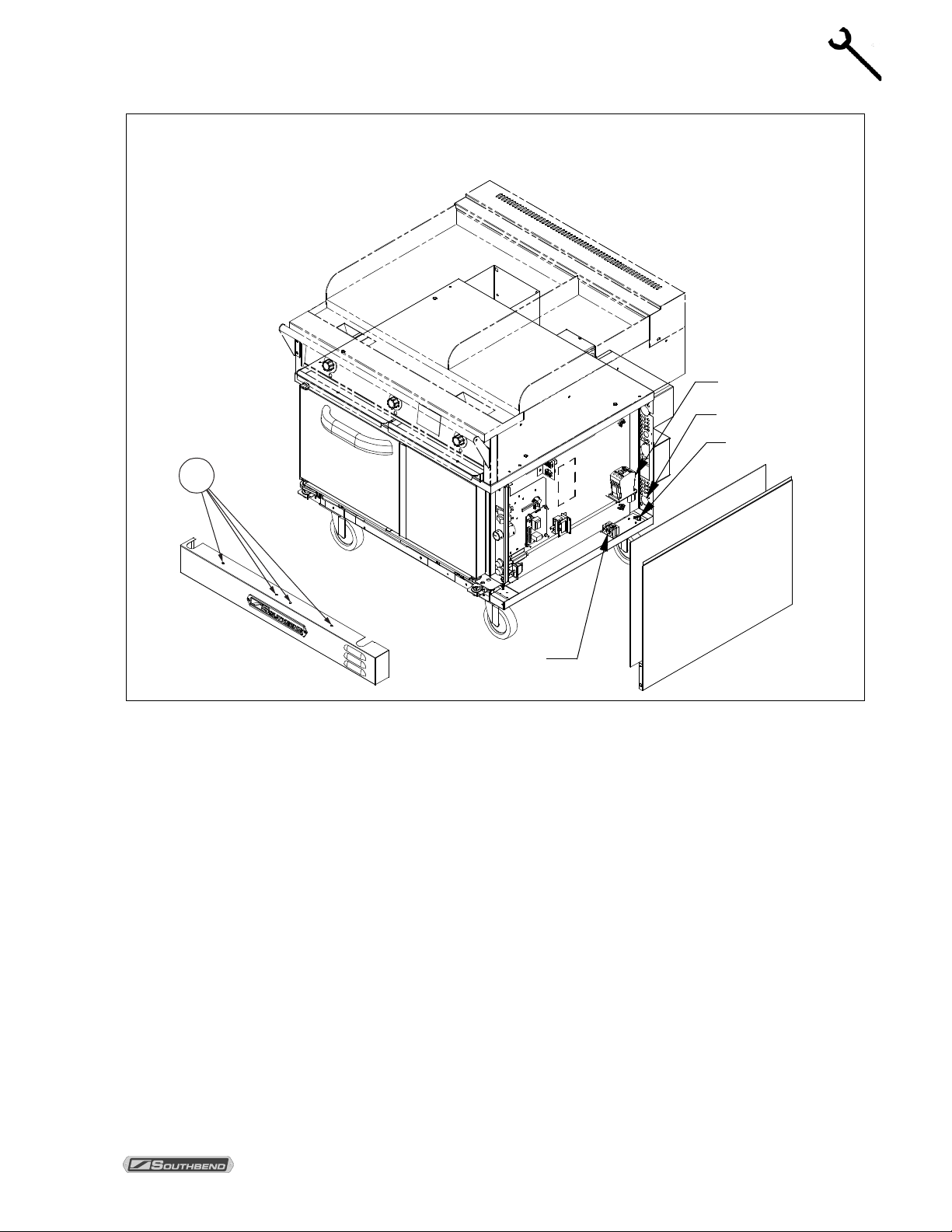
CONVERSION OF OVEN FROM 1-PHASE TO 3-PHASE POWER (OR VICE VERSA)
Ovens are shipped wired for 1-phase power. If the oven installation requires changing the type of power
used by the oven, follow the proc edure below. T he following drawing sho ws the locations of items referr ed
to in the procedure.
1. DISCONNECT OVEN FROM POWER SUPPLY.
2. Locate and remove the four scr ews that secure the l ower front pan el (items “A” in the drawing above).
Lift up the panel and pull it forward to remove it, and then set it aside.
3. Locate and remove the two now-accessible screws that secure the lower front corner of the side panel.
4. Locate and remove the three screws that secur e the back edge of the side panel to t he oven. R emove
the side panel and insulation and set them aside.
5. Locate the wires running from the s upply-power terminal block to the con tactor. If converting from 3phase to 1-phase power, re m ove the wire T 2 (as s hown in the f ollowin g drawing) and go on to the nex t
step. If converting from 1-phas e to 3-phase power, locate the wires runn ing from the contactor to the
elements. Attached to thos e wires (with a wire tie) will be t wo wires that are not being used. Use the
shorter of the two extra wir es to make the additional connection ( T2) shown in the following drawin g.
Keep the longer wire to us e in th e nex t step. (Note: If you are c ha ng ing th e phas e-wiring of a 380/415V
oven, refer to the corresponding wiring diagram for conversion. See page 40.)
PAGE 34 OWNER’S MANUAL 1195746
Page 35

WENDY’S ELECTRIC RANGE ADJUSTMENTS
ADJUSTMENTS
Wiring is different for 380/415V ovens; refer to corresponding wiring diagram (see page 40).
6. Locate the wires running from the contactor to the elements. If converting from 3-phase to 1-phase
power, remove the wire L2 (as shown i n the above dra wing) and go on to the next step. If conv erting
from 1-phas e to 3-phase power, use the longer of the t wo extra wires foun d in the previous ste p to
make the additional connection (L2) shown in the above drawing. (Again, if you are changing the
phase-wiring of a 380/415V ov en, refer to the correspondin g wiring diagram for conversio n. See page
40.)
7. Rewire the connections to the elements (located o n the back of the oven) according to the diagram on
this page. I f convert ing from 3-phase to 1-ph ase, use the wire that you saved in Step 2 to mak e one of
the connections. (Onc e more, if you are changing th e phase-wiring of a 380/415V oven, refer to t he
corresponding wiring diagram for conversion. See page 40.)
8. Carefully compare the new wiring connections at the elements, contactor, and supply-power
terminal block to the wiring diagram for the oven. (A wiring diagr am is located on the side of the
control panel assembly, see page 37; or see the appropriate wiring diagram printed in this manual,
beginning on page 38). Verify that all connections are tight.
9. Reattach the right-side insulation, right-side panel, and lower-front panel.
10. Connect the oven to the power supply. Note that the supply-power connections depend on
whether the supply power is 3-phase or 1 phase, and so will be different than they were prior to
the conversion.
11. Double-check supply-wire sizing for new amperage load (see page 5).
OWNER’S MANUAL 1195746 PAGE 35
Page 36

TROUBLESHOOTING WENDY’S ELECTRIC RANGE
TROUBLESHOOTING
TROUBLESHOOTING
WARNING
ADJUSTMENTS AND SERVICE WORK MAY BE PERFORMED ONLY BY A QUALIFIED
TECHNICIAN W HO IS EXPERIENCED IN, AND KNOW LEDGEABLE WITH , THE OPERATION OF
COMMERCIAL COOKING EQUIPMENT. HOWEVER, TO ASSURE YOUR CONFIDENCE,
CONTACT YOUR AUTHORIZED SERVICE AGENCY FOR RELIABLE SERVICE, DEPENDABLE
ADVICE OR OTHER ASSISTANCE, AND FOR GENUINE FACTORY PARTS.
NOTICE
Warranty will be void and the m anufacturer is relieved of all liabilit y if service work is performed b y
other than a qualified technician, or if other than genuine Southbend replacement parts are installed.
When any difficult y arises it is always a good idea to check that the oven has b ee n c onnec te d to th e t ype of
voltage for which it was manufac tured. The range-top ser ial plate is located on the interior side of the top
front panel, while the oven-base serial plate is located on the interior side of the lower front panel, as
shown on page 3. The serial plate will list the type of voltage for which the unit was manufactured. In
addition, a wiring diagram for the oven base is attached to the side of the oven-base slide-out control panel,
while a wiring diagram for the range top is located on the interior side of the rear access panel. Wiring
diagrams are also reproduced in this manual (beginning on page 38).
TROUBLESHOOTING GUIDE
The left column of the following table lists symptoms that indicate a problem, while the center and right
columns list the possible c auses and appropriate cor rective action. Note that the recommendations of this
table assume that the wiring connec tions are good . When check ing a component , always chec k the wiring
attached to the component as well.
Symptom Possible Cause Check or Replace
Oven will not operate,
but range top will.
Oven will not hold
correct temperature.
Temperature control not calling for heat.
Inadequate or improper ventilation. Check ventilation hood. Verify draw and make up air adjustment.
Out of calibration. Calibrate according to procedure described on page 32.
Bad contactor. Verify that contactor is pulling in and supplying power to the elements.
Blower motor will not
come on.
Loose wire connections. Check wire connections.
Motor bad. If power is being supplied but motor will not turn, replace motor.
Shut down switch bad.
POWER switch bad.
FAN MODE switch bad. Check FAN MODE switch.
Blown oven fuses. Check oven fuses located on oven-base control panel (see page 21).
Temperature probe not working.
No incoming electric power. Check incoming power and fuses.
Resistance across temperature probe leads at room temperature (70°F,
21°C) should be approximately 1096 ohms.
When heat is required, there should be continuity between terminals 6
and 7 on temperature control.
All power except for element supply comes through the shut down
switch. Check for continuity.
All power except for element supply comes through the POWER switch.
Check for continuity.
PAGE 36 OWNER’S MANUAL 1195746
Page 37

WENDY’S ELECTRIC RANGE TROUBLESHOOTING
TROUBLESHOOTING
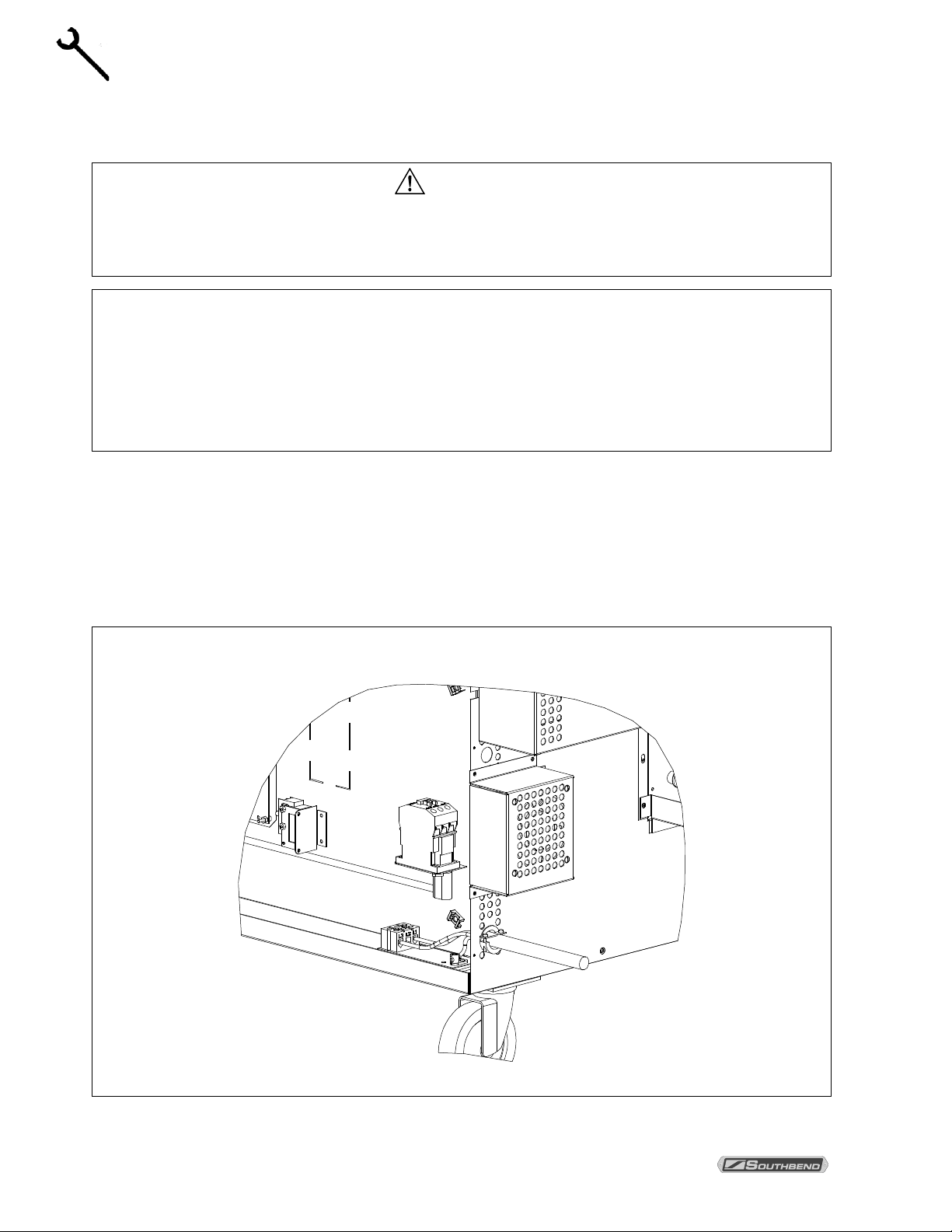
CONTROL PANEL ACCESS AND SHUT-OFF SWITCH
To access the oven-base control panel components , remove the thumb screws at the top and bottom of the
control panel and pull the control pa nel out (see drawing below). A wiring di agram for the oven is located
on the side of the control panel assembly. When the control panel is pulled out, all power to the control
panel is cut off by a shut down switch that is located directly behind and below the control panel.
To re-energize the controls for troubleshooting, push in the plunger on the shut down switch.
Accessing Lower Control Panel Components
BLOWER WHEEL REPLACEMENT
To replace the blower wheel, do the following:
1. Remove racks and rack guides.
2. Remove rear air baffle in front of blower wheel.
3. Loosen the two square heads on blower wheel hub.
4. Pull blower wheel from motor shaf t. If blower wheel is diff icult to pull of f, use pu ller disk (availab le from
Southbend Technical Service department as part number 1179100).
OWNER’S MANUAL 1195746 PAGE 37
Page 38

TROUBLESHOOTING WENDY’S ELECTRIC RANGE
TROUBLESHOOTING
COIL
CONTACTOR
NOTE:
ELEMENTS ARE 2500WATTS EACH
3 PHASE
CONTACTOR
1 PHASE
L1 L2 L3
X Y
Z
TB1
Wiring Diagram for 208/240 Volt Ovens
PAGE 38 OWNER’S MANUAL 1195746
Page 39

WENDY’S ELECTRIC RANGE TROUBLESHOOTING
TROUBLESHOOTING
COIL
CONTACTOR
NOTE:
ELEMENTS ARE 2500WATTS EACH
3 PHASE
L1
CONTACTOR
L2 L3
1 PHASE
X Y
Z
TB1
Wiring Diagram for 480 Volt Oven
OWNER’S MANUAL 1195746 PAGE 39
Page 40

TROUBLESHOOTING WENDY’S ELECTRIC RANGE
TROUBLESHOOTING
COIL
CONTACTOR
NOTE:
ELEMENTS ARE 2500WATTS EACH
3 PHASE
ELEMENTS
L1
CONTACTOR
L2 L3
1 PHASE
TB1 TB2
N
Wiring Diagram for 380/415 Volt Wye Ovens
PAGE 40 OWNER’S MANUAL 1195746
Page 41

WENDY’S ELECTRIC RANGE TROUBLESHOOTING
TROUBLESHOOTING
125
135
165
Wiring Diagram for 208/240 Volt Range Tops
OWNER’S MANUAL 1195746 PAGE 41
Page 42

TROUBLESHOOTING WENDY’S ELECTRIC RANGE
TROUBLESHOOTING
125
135
165
Wiring Diagram for 480 Volt Range Top
PAGE 42 OWNER’S MANUAL 1195746
Page 43

WENDY’S ELECTRIC RANGE TROUBLESHOOTING
TROUBLESHOOTING
125
135
165
Wiring Diagram for 380/415 Volt Wye Range Tops
OWNER’S MANUAL 1195746 PAGE 43
Page 44

WENDY’S ELECTRIC RANGE
Wendy’s Electric Range
A product with the So uthbend name incor porates the best in d urability and low m aintenance. We
all recognize, however, that replacement parts and occasional professional service may be
necessary to extend the useful life of this unit. When service is needed, contact a Southbend
Authorized Service Age nc y, or your dea ler. T o avoid c onfus ion, al ways ref er to th e m odel num ber,
serial number, and type of your unit.
Southbend
1100 Old Honeycutt Road, Fuquay Varina, NC 27526 USA
www.southbendnc.com
PAGE 44 OWNER’S MANUAL 1195746
 Loading...