

Page 1
FOR FUTURE REFERENCE
WARNING: Improper installation, adjustment, alteration, service
$9.00
Please complete this information
and retain this manual for the life
of the equipment.
MODEL #
SERIAL #
DATE PURCHASED
OWNER'S MANUAL
INSTALLATION
USER'S GUIDE
SERVICE
PARTS
IMPORTANT
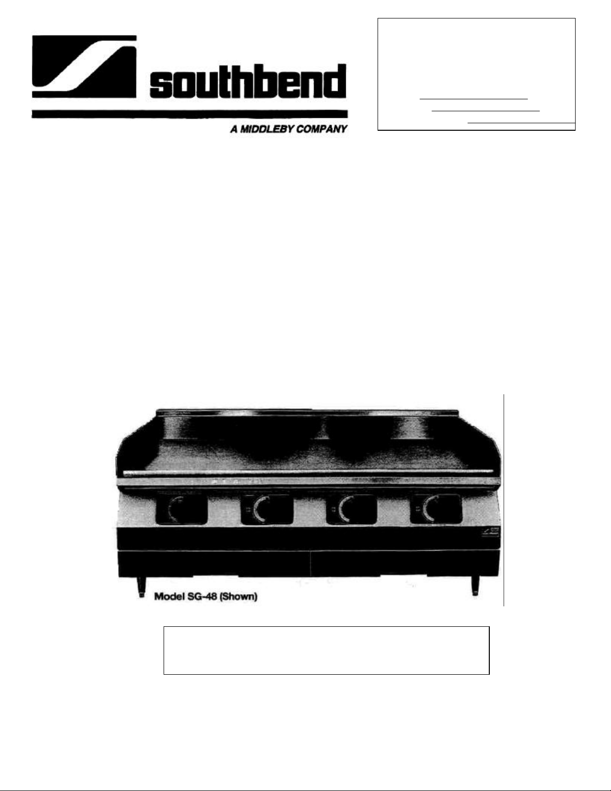
COUNTER GRIDDLE
MODELS: SG-24, SG-24E; SG-36, SG-36E
SG-48, SG-48E; SG-60, SG-60E
SG-72, SG-72E
or maintenance can cause propertydamage, injury or death . Read
the installation, operating and maintenance instructions
thoroughly before installing or servicing this equipment.
1100 Old Honeycutt Road • Fuquay, NC 27526 • (919) 552-9161 • FAX (919) 552-9798 • (800) 348-2558
Middleby Corp. Service Hot Line (800) 238-8444
COUNTER GRIDDLE
(Manual Section BP)
Page 2
RETAIN THIS MANUAL FOR FUTURE REFERENCE
WARNING
NOTICE
POST IN PROMINENT LOCATION, THE EMERGENCY TELEPHONE
NUMBER OF YOUR LOCAL GAS SUPPLIER AND INSTRUCTIONS TO
BE FOLLOWED IN THE EVENT YOU SMELL GAS.
Instructions to be followed in the event the user smells gas shall be obtained by consulting
the local gas supplier. If the smell of gas is detected, immediately call the emergency
phone number of your local Gas Company. They will have personnel and provisions
available to correct the problem.
FOR YOUR SAFETY
DO NOT STORE OR USE GASOLINE
OR OTHER FLAMMABLE VAPORS AND LIQUIDS
IN THE VICINITY OF THIS OR ANY OTHER APPLIANCE.
NOTICE
This product is intended
for commercial use only.
NOT FOR HOUSEHOLD USE.
EQUIPMENT MUST BE KEPT FREE
AND CLEAR OF COMBUSTIBLES
WARNING
AT ALL TIMES.
Southbend (manufacturer) reserves the right to change
specifications and product design without notice. Such
revisions do not entitle the buyer to corresponding changes,
improvements, additions or replacements for previously
purchased equipment.
WARNING
Warranty will be void and the manufacturer is relieved of all liability IF...
(A) Service work is performed by other than a qualified technician
OR...
(B) Other than Genuine Southbend replacement parts are installed.
WARNING
DO NOT OBSTRUCT THE FLOW OF COMBUSTION
AND VENTILATION AIR TO AND FROM YOUR GAS
COOKING EQUIPMENT.
Page 3

Congratulations! You have just purchased one of the finest pieces of heavy-duty, commercial cooking equipment on the market
today.
You will find that your new equipment, like all Southbend equipment, has been designed and manufactured to some of the
toughest standards in the industry — those of Southbend. Each piece of Southbend equipment has been carefully engineered
and designs have been verified through laboratory tests and field installations in some of the more strenuous commercial
cooking applications. With proper care and field maintenance, you will experience years of reliable, trouble -free operation from
your Southbend equipment. To get the best results, it's important that you read this manual carefully.
TABLE OF CONTENTS:
SECTION ONE - INSTALLATION
Specifications 1
Installation 2
SECTION TWO - USER'S GUIDE
Warranty 1
Operation 2
Maintenance 5
SECTION THREE - SERVICE
Adjustments 1
Troubleshooting 3
SECTION FOUR - PARTS
Parts List 2
INSPECT FOR SHIPPING DAMAGE
All containers should be examined for damage before and during unloading. The freight carrier has assumed
responsibility for its safe transit and delivery. If equipment is received damaged, either apparent or concealed,
a claim must be made with the delivering carrier.
A) Apparent damage or loss must be noted on the freight bill at the time of delivery. It must then be signed
by the carrier representative (Driver). If this is not done, the carrier may refuse the claim. The carrier can
supply the necessary forms.
B) Concealed damage or loss if not apparent until after equipment is uncrated, a request for inspection must
be made to the carrier within 15 days. The carrier should arrange an inspection. Be certain to hold all
contents plus all packaging material.
1100 Old Honeycutt
Road Puquay, NC
27526 (919) 552-9161
FAX (919) 552-9798
(800) 348-2558
Page 4

COUNTER GRIDDLE
USER'S GUIDE
LIMITED WARRANTY
Southbend warrants that the equipment, as supplied by the factory to the original purchasers, is free from defects in materials
and workmanship. Should any part thereof become defective as a result of normal use within the period and limits defined
below, then at the option of Southbend such parts will be repaired or replaced by Southbend or its Authorized Service Agency.
This warranty is subject to the following conditions:
If upon inspection by Southbend or its Authorized Service Agency it is determined that this equipment has not been used in an
appropriate manner, has been modified, has not been property maintained, or has been subject to misuse or misapplication,
neglect, abuse, accident, damage during transit or delivery, fire, flood, riot or Act of God, then this warranty shall be void.
Specifically excluded under this warranty are claims relating to installation; examples are improper utility connections and
improper utilities supply. Claims relating to normal care and maintenance are also excluded; examples are calibration of
controls, and adjustments to pilots and burners.
Equipment failure caused by inadequate water quality is not covered under warranty. WATER QUALITY must not exceed the
following limits: Total Dissolved Solids (TDS) - 60 PPM (Parts Per Million). Hardness - 2 Grains or 35 PPM, PH Factor - 7.0 to
7.5. Water pressure 30 PSI minimum, 60 PSI maximum. Boiler maintenance is the responsibility of the owner and is not
covered by warranty.
This equipment is intended for commercial use only. Warranty is void if equipment is installed in other than commercial
application.
Repairs under this warranty are to be performed only by a Southbend Authorized Service Agency. Southbend can not be
responsible for charges incurred from other than Authorized Southbend Agencies.
THIS WARRANTY MUST BE SHOWN TO AN AUTHORIZED SERVICE AGENCY WHEN REQUESTING IN-WARRANTY
SERVICE WORK. THE AUTHORIZED SERVICE AGENCY MAY AT HIS OPTION REQUIRE PROOF OF PURCHASE.
This warranty does not cover services performed at overtime or premium labor rates nor does Southbend assume any liability
for extended delays in replacing or repairing any items in the equipment beyond the control of Southbend. "Southbend shall
not be liable for consequential or special damages of any nature that may arise in connection with such product or part."
Should service be required at times which normally involve overtime or premium labor rates, the owner shall be charged for
the difference between normal service rates and such premium rates.
In all circumstances, a maximum of one hundred miles in travel and two and one half hours (2.5) travel time shall be allowable.
In all cases the closest Southbend Authorized Agency must be used.
The actual warranty time periods and exceptions are as follows:
This warranty only covers product shipped into the 48 contiguous United States and Hawaii, one year labor, one year parts
effective from the date of original purchase. There will be no labor coverage for equipment located on any island not
connected by roadway to the mainland.
Exceptions to standard warranty, effective within above limitations:
Glass Windows, Door Gaskets, Rubber Seals, Light Bulbs, Ceramic Bricks,
Sight Glasses, Cathodic Descalers or Anodes............................................. 90 days material and labor
Stainless Steel Fry Pot.............................4 years extended material warranty on fry pot only—no labor
Stainless Steel Open Top Burners ............... 4 years extended material warranty on burners only — no labor
Pressure Steam Boiler Shell.................. Prorated 4 years extended warranty on boiler shell only — no labor
Boiler shells which have not been properly maintained will not be covered by warranty.
In all cases parts covered by a five year warranty will be shipped FOB the factory after the first year.
Our warranty oh all replacement parts which are replaced in the field by our Authorized Service Agencies will be limited to
three months on labor, six months on materials (parts) effective from the date of installation. See LIMITED WARRANTY REPLACEMENT PARTS for conditions and limitations.
If the equipment has been changed, altered, modified or repaired by other than a qualified service technician during or after
the one year limited warranty period, then the manufacturer shall not be liable for any damages to any person or to any
property which may result from the use of the equipment thereafter.
"THE FOREGOING WARRANTY IS IN LIEU OF ANY AND ALL OTHER WARRANTIES EXPRESSED OR IMPLIED
INCLUDING ANY IMPLIED WARRANTY OF MERCHANTABILITY OR FITNESS, AND CONSTITUTES THE ENTIRE
LIABILITY OF SOUTHBEND. IN NO EVENT DOES THE LIMITED WARRANTY EXTEND BEYOND THE DURATION OF
ONE YEAR FROM THE EFFECTIVE DATE OF SAID WARRANTY."
USER’S GUIDE
COUNTER GRIDDLE
SECTION TWO — USER'S
GUIDE
PAGE 1
Page 5
JOB___________ ITEM # ___________
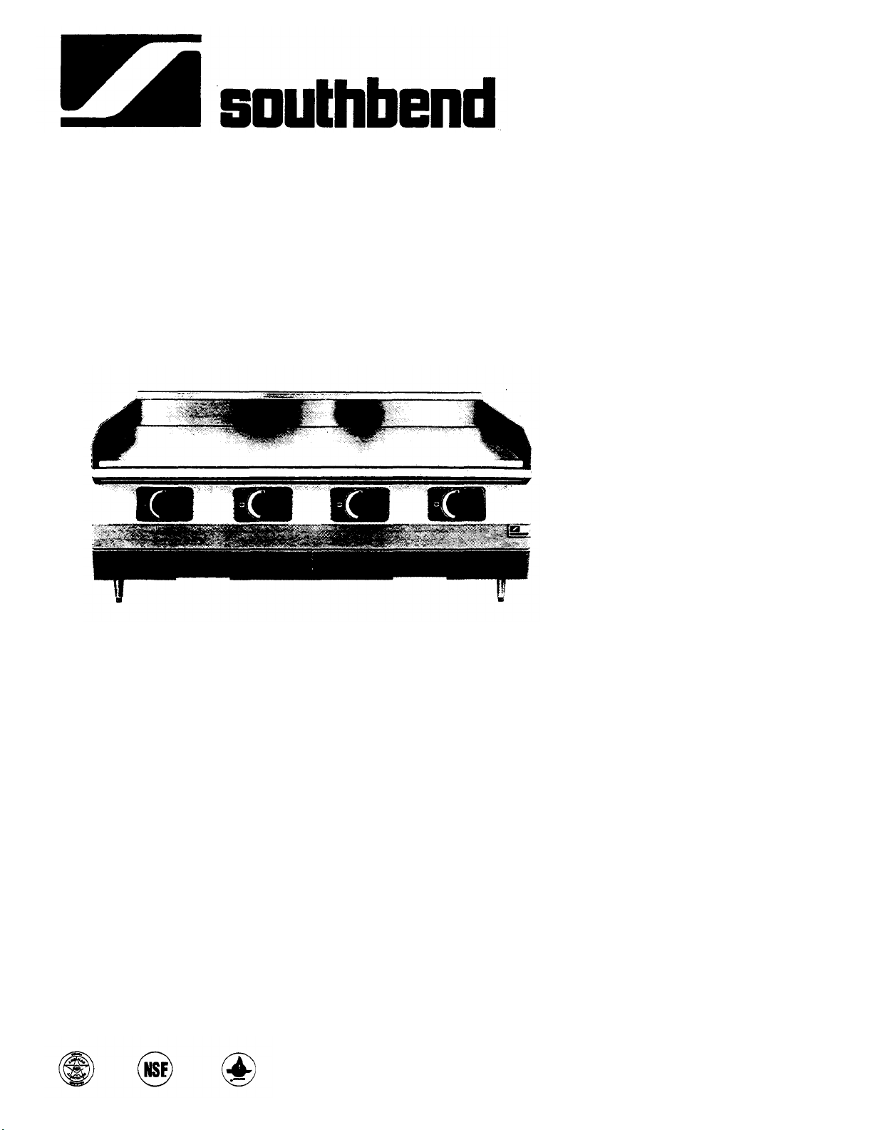
Southbend Thermostatic Counter Griddles
OPTIONS:
o
o
COUNTER GRIDDLE
Gas, Heavy Duty
MODELS: SG-24, SG-36, SG-48, SG-60, SG-72
offer unsurpassed performance, combining
proven control systems with Southbend quality
and durability.
Standard Features:
• One inch thick polished rolled steel plate with
• Stainless steel front and sides.
• Flame failure safety device—Standard.
• 3/4" rear gas connection and pressure
Capabilities:
• Independent thermostatic controls for precise
• 30,000 BTU burner every 12".
• Extremely uniform heat distribution across surface.
• Unsurpassed combustion efficiency.
Cleanability:
• 4" NSF approved legs.
• Spatula width grease trough.
• Hidden grease drawer with large capacity.
• Stub back interlocks with splash guard rear
A MIDDLEBY COMPANY
4" high rear and side splash guards.
regulator.
temperature settings between 150'Fand450"F.
to eliminate spills between plate and stub
back.
Model SG-48 — Stainless steel front and sides standard.
o
Stainless steel stand
o
Stainless steel Intermediate shelf for
o
Casters for stand
o
2" Insulator base
o
Stainless rear and bottom
o
Fully or partially grooved griddle plate
Hard chrome griddle plate surface
5/8” Thick polished steel plate
• INQUIRE TO FACTORY FOR SPECIAL OR
CUSTOM REQUIREMENTS
We reserve the right to change specifications and
product design without notice. Such revisions do not
entitle the buyer to corresponding changes,
improvements, additions or replacements for
previously purchased equipment. Southbend has a
policy of continuous product research and
improvement.
All Units:
Stainless steel front and sides standard. Rear
and bottom panels are aluminized steel. A 5"
stainless steel stub back is include at no charge.
Reinforced double wall sides are fully
insulated.
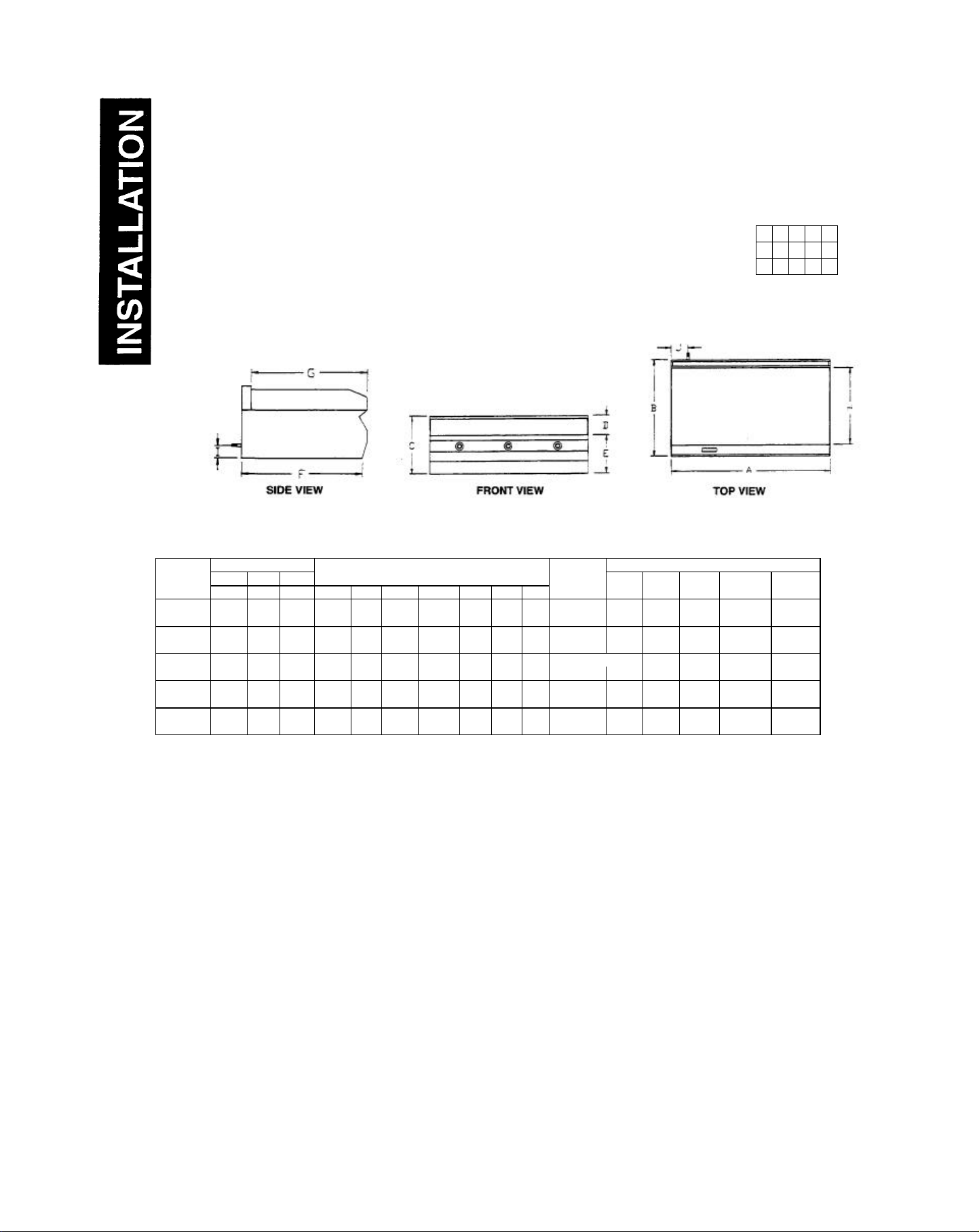
Technical Data
Unit dimensions, utility information, construction
specifications and miscellaneous information is
listed on the reverse side.
Warranty
One year parts and labor warranty at no extra
charge from the date of purchase.
1100 Old Honeycutt Road
Fuquay, NC 27526
(919)552-9161
FAX (919) 552-9798
(800) 348-2558 Page CL-01
Page 6
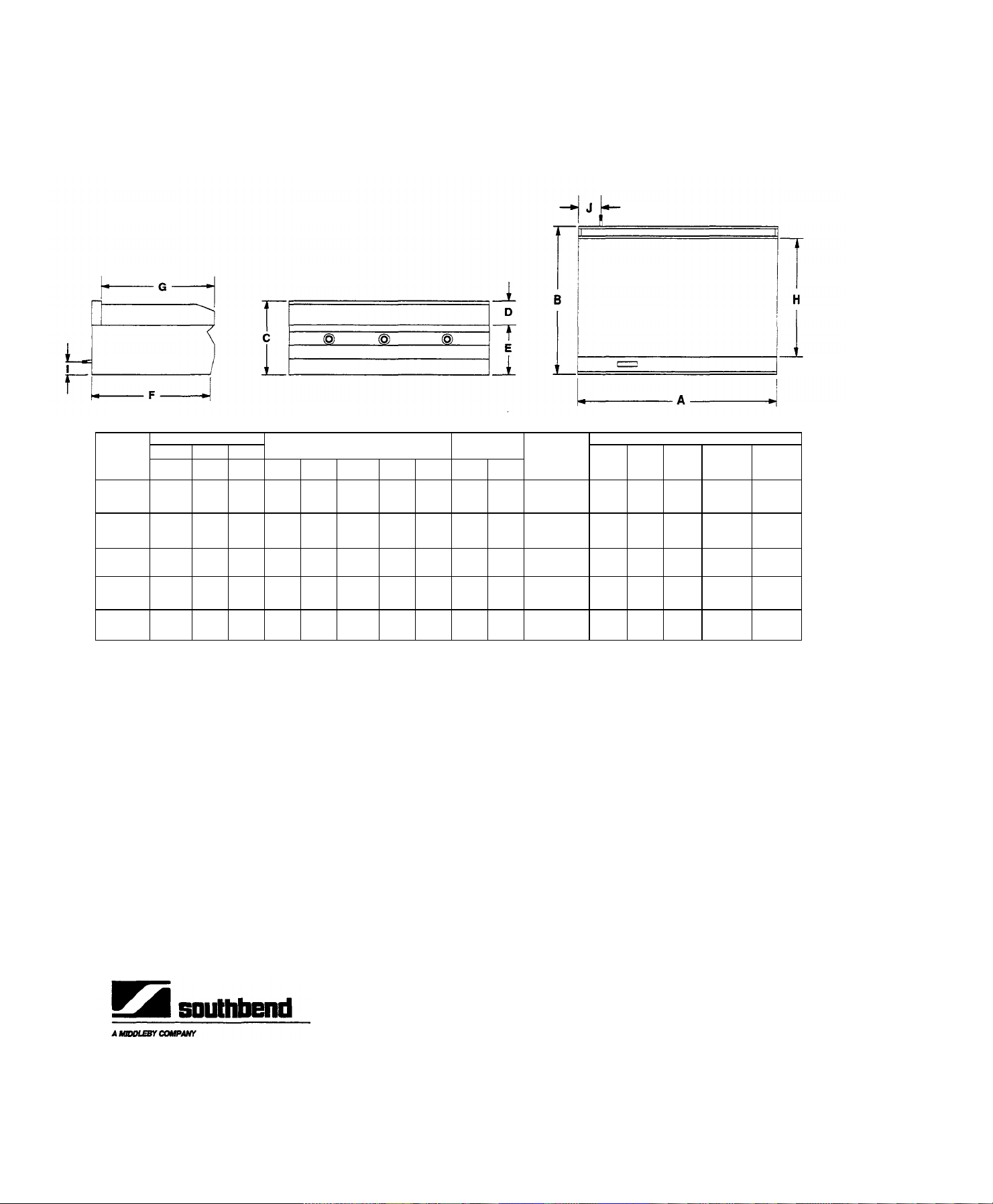
MODELS: o 50-24 o SG-SG o SG-48 oSG-60 o SG-72
EXTERIOR
CRATE SIZE
1100
Old Honeycutt Road
For dimensional purposes only. Not for scale.
MODELS
o SG-24
o SG-36
o SG-48
o SG-60
o SG-72
Width Depth Height
A B C D E F G H I J
24"
30"
18"
5"
5"
5"
5"
5"
13"
(330)
13"
(330)
13"
(330)
13"
(330)
13"
(330)
(610)
36"
(914)
48"
(1219)
60"
(1524)
72"
(1829)
(762)
30"
(762)
30"
(762)
30"
(762)
30"
(762)
(457)
18"
(457)
18'
(457)
18"
(457)
18"
(457)
(127)
(127)
(127)
(127)
(127)
287/8”
(733)
287/8”
(733)
287/8”
(733)
287/8”
(733)
287/8”
(733)
27 ¾ ‘
(704)
27 ¾ ‘
(704)
27 ¾ ‘
(704)
27 ¾ ‘
(704)
27 ¾ ‘
(704)
PERFORMANCE SPECIFICATIONS:
BTU Rating: Each burner rated 30,000 BTU/hour "natural" and "propane"
gas. 2 burners on 24" wide models for total of 60,000 BTU/hour, 3 burners
on 36" wide models for total of 90,000 BTU/hour, 4 burners on 48" wide
models for total of 120,000 BTU/hour, 5 burners on 60" wide models for
total of 150,000 BTU/hour, 6 burners on 72" wide models for total of
180,000 BTU/hour.
Preheat Time: Approximately 25 minutes to 350T.
INSTALLATION SPECIFICATIONS:
Free Standing Models: Required operating pressures are 4" W.C. for
"natural" gas and 10" W.C. for "propane" gas. 3/4TMPT rear gas with pressure regulator is standard.
Flex Hose: Use only a commercial flex hose. The I.D. should not be
smaller than the I.D. of the pipe from the unit to which it is connected.
24"
(610)
24"
(610)
24"
(610)
24"
(610)
24"
(610)
3/4" GAS
CONNECTION
2 3/8”
(60)
2 3/8”
(60)
2 3/8”
(60)
2 3/8”
(60)
2 3/8”
(60)
BURNERS
(BTUea.)
1 ¾”
(45) 2 (30,000)
1 ¾”
(45)
1 ¾”
(45) 4 (30,000)
1 ¾”
(45) 5 (30,000)
1 ¾”
(45) 6 (30,000)
3
(30,000)
Width Depth Height
31"
39"
39"
39"
39"
(991)
39"
(991)
24"
(610)
24"
(610)
24"
(610)
24"
(610)
24"
(610)
(787)
55"
(1397)
55"
(1397)
67"
(1702)
80"
(1702)
(991)
(991)
(991)
Cubic
Volume
16.8cu.ft.
.47 cu. m.
28.9cu.ft
.81 cu. m.
28.9cu.ft.
.81 cu. m.
36.3cu.ft.
1.1 cam.
43.3cu.ft.
1.3 cam.
CONSTRUCTION BIDDING SPECIFICATIONS:
Cabinet: Front, sides, and 5" riser are all stainless steel. Rear and bottom
panels are aluminized steel. Reinforced double wall sides are fully insulated.
Griddle Plate: One inch thick polished rolled steel plate.
Gas/Heat Control Systems: Each foot of griddle is heated by a "U"-
shaped burner. Each burner is controlled by a thermostatic gas valve for
independent temperature control. One standing pilot services up to 4
burners. Each pilot is equipped with a flame failure safety device. 3/4" rear
gas with pressure regulator is standard. Units over 48" wide are
constructed of two bodies.
Approvals: A.G.A. and C.G.A. design certified, N.S.F. listed.
Crated
Weight
305 lbs.
445 lbs.
545 Ibs.
705 Ibs.
890 lbs.
Southbend, in line with its policy to continually improve its products, reserves the right to change materials or specifications without notice.
INTENDED FOR COMMERCIAL USE ONLY. NOT FOR HOUSEHOLD USE.
PageCL-02 Printed in U.S.A. 1/94 FormCL01/02
Fuquay, NC 27526
(919)552-9161
FAX (919) 552-9798
(800)348-2558
Page 7
COUNTER GRIDDLE
INSTALLATION
Not For Scale For Dimensional
Litho in U.S.A.
COUNTER GRIDDLE SECTION
SPECIFICATIONS
Purposes Only
DIMENSIONS: ( ) = Millimeters
MODELS
? SG-24 24" 30" 18" 5" 13" 28 7/8" 27 7/8' 24" 23/8" 13/4"
? SG-24E (610) (762) (457) (127) (330) (733) (704) (610) (60) (45) (30,000) (787) (991) (610) .47 cu. m.
? SG-36 36" 30" 18" 5" 13" 28 7/8" 277/8' 24" W 13/4"
? SG-36E (914) (762) (457) (127) (330) (733) (704) (610) (60) (45) (30.000) (1397) (991) (610) .81 cu. m.
? SG-48 48" 30" 18" 5" 13" 28 7/8" 277/8' 24" 23/8" 13/4"
? SG-48E (1219) (762) (457) (127) (330) (733) (704) (610) (60) (45) (30.000) (1397) (991) (610) .81 cu. m.
? SG-60 60" 30" 18" 5" 13" 28 7/8" 277/8' 24" 23/8" 13/4"
? SG-60E (1524) (762) (457) (127) (330) (733) (704) (610) (60) (45) (30,000) (1702) (991) (610) 1.1 cu. m.
? SG-72 72" 30* 18" 5" 13" 28 7/8" 277/8' 24" 23/8" 13/4"
? SG-72E (1829) (762) (457) (127) (330) (733) (704) (610) (60) (45) (30.000) (1702) (991) (610) 1.3 cu. m.
EXTERIOR CRATE SIZE
Width Depth Height
A B C D E F G H I J
3/4" GAS
CONNECTION
BURNERS
(BTU ea.)
Width Depth Height
2 31" 39" 24" 16.8cu.ft.
3 55- 39" 24" 28.9cu.ft.
4 55" 39" 24" 28.9 cu. ft.
5 67" 39" 24" 36.3 cu. ft.
6 80" 39" 24" 43.3 cu. ft.
Cubic
Volume
Crated
Weight
305 Ibs.
445 Ibs.
545 Ibs.
705 Ibs.
890 Ibs.
PERFORMANCE SPECIFICATIONS:
BTU Rating: Each burner rated 30,000 BTU/hour "natural"
and "propane" gas. 2 burners on 24" wide models for total of
60,000 BTU/hour, 3 burners on 36" wide models for total of
90,000 BTU/hour, 4 burners on 48" wide models for total of
120,000 BTU/hour, 5 burners on 60" wide models for total of
150,000 BTU/hour, 6 burners on 72" wide models for total of
180,000 BTU/hour. Preheat Time: Approximately 13 minutes
to 350°F.
INSTALLATION SPECIFICATIONS:
Free Standing Models: Required operating pressures are 4"
W.C. for "natural" gas and 10" W.C. for "propane" gas. 3/4"
NPT rear gas with pressure regulator is standard.
Flex Hose: Use only a commercial flex hose. The I.D. should
CONSTRUCTION BIDDING
SPECIFICATIONS:
Cabinet: Front, sides, and 5" riser are all stainless steel. Rear
and bottom panels are aluminized steel. Reinforced double
wall sides are fully insulated. Griddle Plate: One inch thick
polished rolled steel plate.
Gas/Heat Control Systems: Each foot of griddle is heated by
a "U"-shaped burner. Each burner is controlled by a
thermostatic gas valve for independent temperature control.
One standing pilot services up to 4 burners. Each pilot is
equipped with a flame failure safety device. 3/4" rear gas with
pressure regulator is standard. Units over 48" wide are
constructed of two bodies.
Approvals: A.G.A. and C.G.A. design certified, N.S.F. listed.
not be smaller than the I.D. of the pipe from the unit to which it
is connected.
Southbend, in line with its policy to continually improve its products, reserves the right to change materials or
specifications without notice.
INTENDED FOR COMMERCIAL USE ONLY. NOT FOR HOUSEHOLD USE.
ONE — INSTALLATION
PAGE 1
2-94
Page 8

INSTALLATION
WARNING: THESE PROCEDURES MUST BE FOLLOWED BY QUALIFIED
GENERAL:
THE UNIT, WHEN INSTALLED, MUST CONFORM WITH LOCAL CODES, OR IN THE ABSENCE OF LOCAL
CODES, WITH THE NATIONAL FUEL GAS CODE, ANSI Z223.1-LATEST EDITION.
THE UNIT, WHEN INSTALLED, MUST BE ELECTRICALLY GROUNDED AND COMPLY WITH LOCAL
CODES, OR LN THE ABSENCE OF LOCAL CODES, WITH THE NATIONAL ELECTRICAL CODE ANSFNFPA
70-LATEST EDITION.
CANADIAN INSTALLATION MUST COMPLY WITH CAN/CGA-B149.1 NATURAL GAS INSTALLATION
CODE, CODE CAN/CGA-B 149.2 PROPANE INSTALLATION CODE, AND CSA C22.1 CANADIAN
ELECTRICAL CODE PARTS I, OR LOCAL CODES.
These models are design certified for operation on Natural or Propane gases.
The appliance should be connected ONLY to the type of gas for which it is equipped. All Southbend equipment is
adjusted at the factory. Check type of gas on serial plate in the compartment behind the front panel, on inside
Right Lining.
NOTE: Each Counter Griddle is a complete unit with an individual 3/4" NPT supply connection at the rear. An
adequate gas supply is imperative. Undersized or low pressure lines will restrict the volume of gas required for
satisfactory performance. A Pressure regulator, which is provided with each unit, is set to maintain a 4" W.C.
manifold pressure for natural gas and a 10" W.C. manifold pressure for propane gas. However, to maintain
these conditions the pressure on the supply line, when all units are operating simultaneously, should not drop
below 7" W.C. for natural gas of 11" W.C. for propane gas.
Counter Griddle units, a 3/4" NPT gas supply connection is located at the right side of rear, when you are facing rear of
the unit.
If applicable, the vent line from the gas appliance pressure regulator shall be installed to the outdoors in accordance with
local codes or, in the absence of local codes, with the National Fuel Gas Code, ANSI Z223.1-LATEST EDITION and
CANADIAN INSTALLATION MUST COMPLY WITH CAN/CGA-B149.1 NATURAL GAS INSTALLATION
CODE, CODE CAN/CGA-B149.2 PROPANE INSTALLATION CODE. A 1/8" pressure tap is located on the manifold
of each unit.
All pipe joints should be tested for leaks with a soap and water solution before operating the unit. The test pressure should
not exceed 14" W.C.
CAUTION: THIS APPLIANCE AND ITS INDIVIDUAL SHUTOFF VALVE MUST BE DISCONNECTED FROM
THE GAS SUPPLY PIPING SYSTEM DURING ANY PRESSURE TESTING OF THE SYSTEM AT TEST
PRESSURES IN EXCESS OF 1/2 PSIG (3.45 kPa).
THIS APPLIANCE MUST BE ISOLATED FROM THE GAS SUPPLY PIPING SYSTEM BY CLOSING ITS
INDIVIDUAL MANUAL SHUTOFF VALVE DURING ANY PRESSURE TESTING OF THE GAS SUPPLY
PIPING SYSTEM AT TEST PRESSURES EQUAL TO OR LESS THAN 1/2 PSIG (3.45 kPa).
PERSONNEL OR WARRANTY WILL BE VOIDED.
INSTALLATION
EXHAUST FANS AND CANOPIES:
An adequate ventilation system is required for the Southbend counter line. The minimum canopy hood dimensions are
outlined as follows:
It is recommended that a canopy extend 6" past appliance and be located 6' 6" from the floor. Filters should be
installed at an angle of 45 degrees or more with the horizontal. This prevents dripping grease and facilitates
collecting the run-off grease in a drip pan, usually installed with a filter. A strong exhaust fan tends to create a
negative pressure condition in the room and may interfere with burner performance, extinguish pilot flames, or
result in poor cooking performance.
To avoid a negative pressure condition, return air must be brought into the room to replenish the air being
removed by the ventilation hood.
This can be accomplished by one of two ways:
A. Return air may be introduced into the room through the heating, ventilation, and air conditioning (HVAC)
system.
B. Return air may come from within the hood itself by using fans internal to the hood system.
NOTE: Return air from fans MUST NOT BLOW DOWN GRIDDLE FLUE OR DIRECTLY ON GRIDDLE
SURFACE.
COUNTER GRIDDLE SECTION
ONE — INSTALLATION
PAGE 2
Page 9
INSTALLATION
In case of unsatisfactory performance on any appliance, check with the exhaust fan in the "OFF" position. Do this
only long enough to check equipment performance. Then turn hood back on and let it run to remove any exhaust that
may have accumulated during the test.
WALL EXHAUST FAN: Should be installed at least 2 feet above the vent opening at the top of the backsplash.
All units must be installed in such a manner that the flow of combustion and ventilation air are not obstructed.
Provisions for an adequate air supply must also be provided.
PROPER VENTILATION IS THE OWNER'S RESPONSIBILITY. ANY PROBLEM DUE
TO IMPROPER VENTILATION WOULD NOT BE COVERED BY WARRANTY.
Local codes regarding installation vary greatly from one area to another. The National Fire Protection Association,
Inc. states in its NFPA 96 latest edition that local codes are "authority having jurisdiction" when it comes to
requirements for installation of equipment. Therefore, installations should comply with all local codes.
TO INSTALL COUNTER MODEL GRIDDLE:
1. Inspect for shipping damage as outlined in front of manual.
2. Cut banding straps and remove corrugated box from griddle.
3. Before cutting banding material holding griddle to wooden skid, move unit as near to the place of installation
as possible.
4. Cut banding strap holding griddle to wooden skid.
5. Locate box marked Legs and box marked Regulator. A gas
pressure regulator is supplied with each Counter griddle and
legs are supplied when unit is ordered with legs. If these
items are not received, contact your Southbend
Sales Representative. Please have your model
and serial numbers ready when you call.
NOTE: If your griddle is to be installed
with legs, proceed to Step 6. If your
griddle is to be installed flat on a
counter or on a stand, move to section
titled "OPTIONAL INSTALLATION."
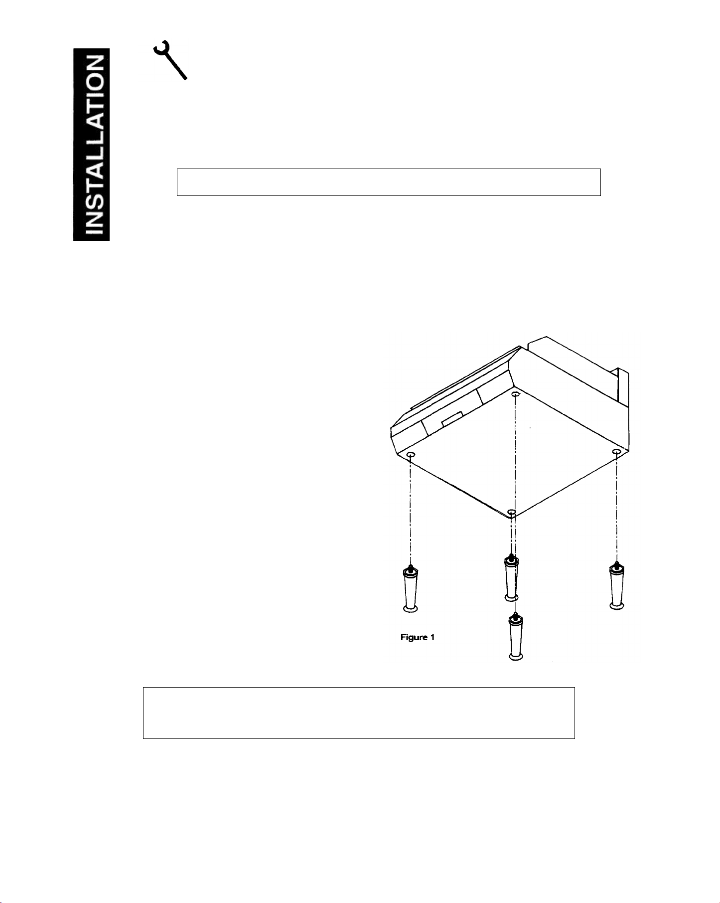
6. Lift griddle from front left and right
comers and tilt back to about 45° angle.
7. Install NSF approved legs supplied with
griddle. Refer to Figure 1 (below).
8. After installing legs on front of griddle base,
SLOWLY lower griddle till the front of
griddle rests on legs.
9. Lift rear of griddle at left and right
comers and install rear legs.
NOTE: If it is necessary to prop griddle up to install legs, support griddle from sides, NOT the
COUNTER GRIDDLE SECTION
ONE — INSTALLATION
PAGE 3
center. Griddle MUST ALWAYS BE LIFTED AND MOVED FROM ENDS — NEVER LIFT
FROM CENTER.
Lithe in U.S.A.
2-94
Page 10
INSTALLATION
ALL MODELS
0 IN. 0
IN.
WARNING: If Griddle is to be installed without legs, the surface the griddle will rest upon must be made of
2.
top using G.E. or Dow Corning RTV or
INSTALLATION
10. Griddle is now ready to be installed on counter. Lift griddle from ends and set in place.
PLEASE NOTE CLEARANCES BELOW:
Minimum clearances from COMBUSTIBLE CONSTRUCTION are:
TYPE SIDES REAR
ALL MODELS
Minimum clearances from NON-COMBUSTIBLE CONSTRUCTION are:
TYPE SIDES REAR
NOTE: No additional clearance from the sides and back is required for service, as the units are serviceable from the
front.
11. Adjust bottom of legs to level griddle.
CAUTION: ONLY NON-COMBUSTIBLE COUNTERS ARE TO BE USED TO SUPPORT THESE UNITS.
OPTIONAL INSTALLATION:
12 IN. 5 IN.
NON COMBUSTIBLE MATERIAL. Follow all local codes.
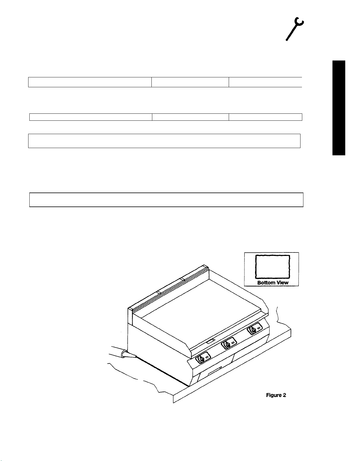
TO INSTALL WITHOUT LEGS:
1. After uncrating and inspecting for shipping damage, lift griddle from ends and place on non-combustible
surface. NOTE: NEVER LIFT GRIDDLE FROM CENTER. GRIDDLE MUST BE LIFTED FROM ENDS.
After setting griddle in place, make your gas supply connection.
(Refer to GAS CONNECTION, Section 1, Page 11.)
3. After making gas connection, seal griddle to counter
equivalent. (NOTE: Consult local code for
exact requirements.) A small bead of
RTV around edge of griddle
bottom should be adequate. Refer
to Figure 2 below.
SECTION ONE — INSTALLATION
COUNTER GRIDDLE
PAGE 4
Page 11
INSTALLATION
COUNTER GRIDDLE
Litho in U.S.A.
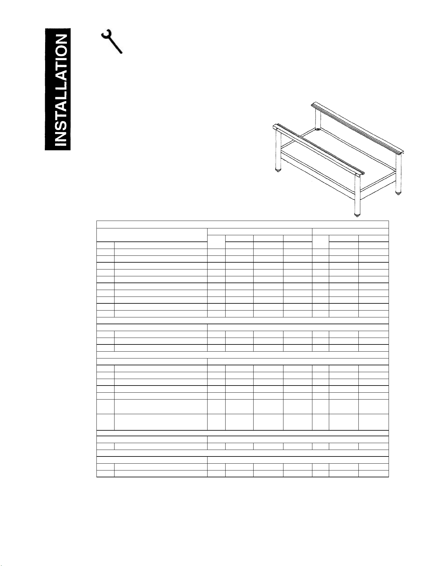
THE STAND FOR SOUTHBEND COUNTER LINE EQUIPMENT MAY BE SHIPPED
DISASSEMBLED. TO ASSEMBLE THE STAND, USE THE FOLLOWING PROCEDURES.
INSTRUCTIONS P/N 1173737
TO INSTALL GRIDDLE ON COUNTER LINE STAND:
1. Uncrate and inspect for shipping damage.
2. Follow assembly instructions below to assemble Counter Line
Stand. Stand may come already assembled. If so, go to Page
10.
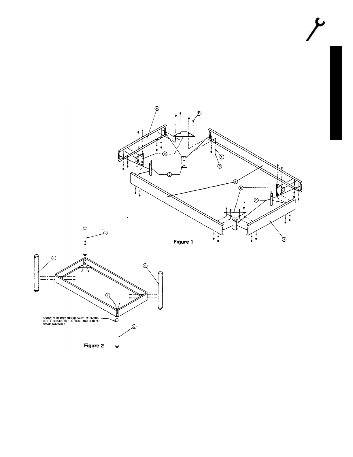
ASSEMBLY INSTRUCTIONS FOR SOUTHBEND
COUNTER LINE STAND
SCL-24, SCL-36, SCL-48, SCL-60, SCL-72
PARTS LIST FOR SOUTH BEND COUNTER LINE STANDS
PARTS FOR STAND
ITEM DESCRIPTION
A Bottom brace/Lt & Rt side 2 1173709 1173709 1173709 4 1173709 1173709
B Bottom brace/front & rear 2 1173710 1173723 1173724 4 1173728 1173729
C Leg bracket 4 1173707 1173707 1173707 8 1173707 1173707
D Comer brace 4 1173706 1173706 1173706 8 1173706 1173706
E ¼ " Lock washer 16 1146500 1146500 1146500 32 1146500 1146500
F ¼” - 20 x11/2 Hex head bolt 16 1146200 1146200 1146200 32 1146200 1146200
G ¼ " - 20 Acorn nut 16 1164827 1164827 1164827 32 1144827 1144827
H ¼ " - 20 x1 ¼ Hex head bolt 8 1146203 1146203 1146203 16 1146203 1146203
I Front & rear top support 2 1173721 1173720 1173722 2 1173879 1173880
J ¼ " - 20 x 5/8 Hex head bolt 4 1146518 1146518 1146518 6 1146518 1146518
ITEM
QTY
MODELS MODELS
SCL-24 SCL-36 SCL-48 SCL-60 SCL-72
P/N P/N P/N
ITEM
QTY
P/N P/N
PARTS FOR STAND WITH LEGS
K Left leg assembly 2 1173590 1173590 1173590 2 1173590 1173590
L Right leg assembly 2 1173589 1173589 1173589 2 1173589 1173589
M Center leg assembly
PARTS FOR STAND WITH CASTERS
N Left caster leg assembly 2 1173592 1173592 1173592 2 1173592 1173592
O Right caster leg assembly 2 1173591 1173591 1173591 2 1173591 1173591
P Center caster leg assembly
Q Caster with lock 2 1174264 1174264 1174264 2 1174264 1174264
R Caster with out lock 2 1174263 1174263 1174263 4 1174263 1174263
Caster package composed 1 1174265 1174265 1174265
(2) of Item Q & (2) of Item R
Caster package composed
(2) of Item Q & (4) of Item R
PARTS FOR STAND WITH SHELF
S Shelf 1 1173717 1173718 1173719 2 1173881 1173882
STAND MOUNT PARTS SENT WITH UNIT
T Mount angle 2 1173725 1173726 1173727 2 1173733 1173878
U #10 x ½ Sheet metal screw 4 1146304 1146304 1146304 6 1146304 1146304
2 1173731 1173731
2 1173732 1173732
1 1173708 1173708
SECTION ONE — INSTALLATION
PAGE 5
2-94
Page 12
INSTALLATION
INSTALLATION
ASSEMBLY PROCEDURE FOR SCL-24, SCL-36, & SCL-48
1. Remove from carton two (2) item "A" bottom brace left and right side, and two (2) item "B" bottom brace
front and rear, and position as shown in Figure 1. Position one (1) item "D" comer brace into each comer
matching prepunched holes on the bottom inside flange of bottom braces.
2. Locate leg bracket item "C," and insert into comer being sure bracket flanges are engaged into open hem of
bottom braces.
3. Using 1/4 - 20 x 1/2 hex head bolts item T," and 1/4 lock washers item "E" along with 1/4 - 20 acorn nut item
"G," secure comer brace to bottom brace on all four comers.
NOTE: Check to be sure leg brackets are still in proper position, and outside comers are square. Only hand tighten
bolts for now.
4. Attach left leg assembly item "K," as shown in Figure 2, and right leg assembly item "L" to frame using ¼ -20 x 1 ¼
hex bolts item "H" from inside of frame. Repeat Step 4 for back side of stand.
NOTE: When installing leg assemblies be sure to have single threaded insert facing outside on the front and rear of
stand. Still only hand tighten bolts for now.
5. Now check the assembled stand, make sure that all legs are straight and all comers are square. Finish tightening all
bolts but do not over tighten.
COUNTER GRIDDLE
SECTION ONE — INSTALLATION
PAGE 6
Page 13
INSTALLATION
INSTALLATION
COUNTER GRIDDLE SECTION
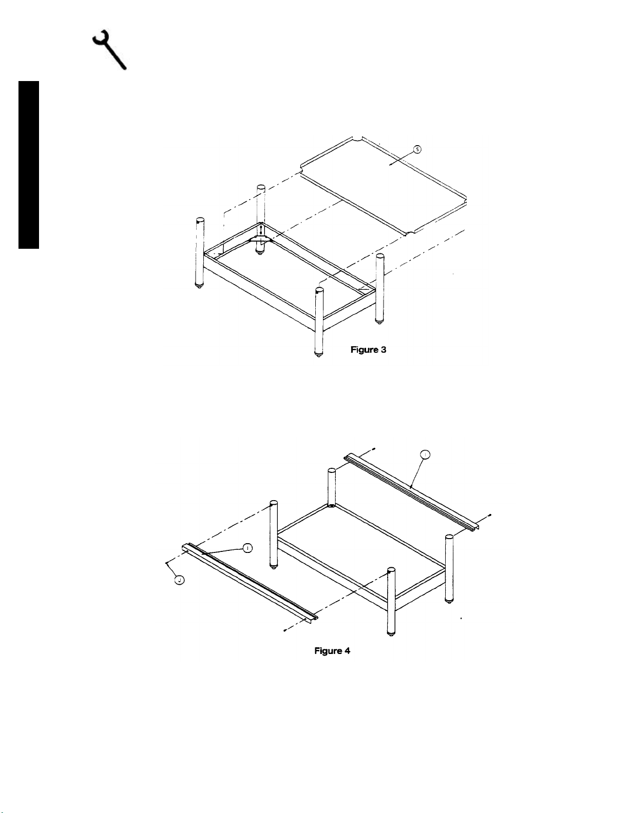
*6. When stand requires casters simply substitute left caster leg assembly Item "N" for Item "K" and right caster leg
assembly Item "O" for Item "L." Screw in casters with lock Item "Q" into front caster leg assemblies, and casters
with out lock Item "R" into rear caster leg assemblies.
*7. Install optional shelf Item "S" between leg assemblies. Down flange on shelf will be to front side of stand. No
mounting screws are necessary. See Figure 3.
8. Position top front and rear support item "I" over leg assemblies as shown in Figure 4. Secure into legs assemblies
with ¼ - 20 x 5/8 hex head bolts Item "J."
*NOTE: Instructions 6 and 7 applied only to those units with optional shelf and casters.
ONE — INSTALLATION
PAGE 7
Litho in U.S.A.
2-94
Page 14

INSTALLATION
ASSEMBLY PROCEDURE FOR SCL-60 & SCL-72
1. Remove from carton four (4) Item "A" bottom brace left and right side, and four (4) item "B" bottom
brace front and rear, and position as shown in Figure 5. Position one (1) item "D" corner brace into each
comer matching prepunched holes on the bottom inside flange of bottom braces.
2. Locate leg bracket Item "C" and insert into corner being sure bracket flanges are engaged into open hem of
bottom braces.
3. Using ¼ -20 x ½ hex head bolts Item "F," and 1/4 lock washers item "E" along with ¼ -20 acorn nut item "G,"
secure corner brace to bottom brace on all eight corners.
INSTALLATION
NOTE: Check to be sure leg brackets are
still in proper position, and outside
comers are square. Only hand
tighten bolts for now.
4. Attach left leg assembly item "K," as
shown in Figure 6, right leg assembly
item "L," and center leg assembly item
"M" to frame using V, - 20 x 1/< hex
bolts item "H" from inside of frame.
Repeat Step 4 for back side of stand.
NOTE: When installing leg assemblies be
sure to have single threaded insert
facing outside on the front and rear
of stand. Still only hand tighten
bolts for now.
5. Now check the assembled stand, make
sure that all legs are straight and all comers are square. Finish tightening all bolts but do not over tighten.
COUNTER GRIDDLE SECTION
ONE—INSTALLATION
PAGE 8
Page 15

INSTALLATION
INSTALLATION
COUNTER GRIDDLE
Litho in U.S.A.
*6. When stand requires casters simply substitute left caster leg assembly item "N" for item "K," right caster leg
assembly item "O" for item "L," and center caster leg assembly item T" for item "M." Screw in casters with lock
item "Q" into left and right front caster leg assemblies, and casters without lock item "R" into rear caster leg
assemblies, and front center caster leg assembly.
*7. Install optional shelves item "S" between leg assemblies. Down flange on shelves will be to front side of stand.
No mounting screws are necessary. See Figure 7.
8. Position top front and rear su_pport item "I" over leg assemblies as shown in Figure 8. Secure into leg assemblies
with V* - 20 x %. hex head bolts item "J."
*NOTE: Instructions 6 and 7 applied only to those units with optional shelf and casters.
SECTION ONE — INSTALLATION
PAGE 9
2-94
Page 16

INSTALLATION
WARNING:
WARNING:
MOUNTING INSTRUCTIONS FOR SCL-24, SCL-36,
SCL-48, SCL-60, SCL-72
Stands for Counter Line are made to hold one or more units. When using the stand, the 4" legs on a Counter Top Unit are
not used. To mount a unit on a stand use the following procedure.
1. Mount angle support brackets item T" to unit using #10 x Yi sheet metal screws item "IT provided as shown in Figure
9. Mounting holes are prepunched for angle mounting.
2. Once brackets are attached, set unit on stand, making sure angle brackets are inserted into top front and rear supports.
No additional attachment is required.
INSTALLATION
For an appliance equipped with casters, the installation shall be made with a connector that
complies with the standard for connectors for movable gas appliances, ANSI Z21.69-1987, CANI
6.10-88, and a quick disconnect device that complies with the standard for quick-disconnect
devices for use with gas fuel, ANSI Z21.41-1978, and addenda, Z21.41a.l981, Z21.41b.l983 and
CANI 6.9 M79. Adequate means must be provided to limit the movement of the appliance
without depending on the connector and the quick-disconnect device or its associated piping to
limit the appliance movement.
If disconnect of this restraint is necessary to remove the appliance for cleaning, etc., reconnect it
when the appliance is moved to its originally installed position.
NOTE: Adequate restraining means must be attached to rear of appliance when installed. Installation must conform to
local codes as applicable.
SECTION ONE — INSTALLATION
COUNTER GRIDDLE
PAGE 10
Page 17

INSTALLATION
INSTALLATION
COUNTER GRIDDLE SECTION
Litho in U.S.A.
GAS CONNECTIONS
1. Each griddle is a complete unit with an individual 3/4" NPT supply connection at the rear. A 3/4" manual gas
shutoff valve is recommended at the gas supply inlet for complete shutdown. Standard pipe fittings are required.
2. The regulator shipped with the unit must be installed at the gas supply inlet. Be sure regulator is connected so that
the gas flow is in the same direction as the arrow on the bottom of the regulator. Refer to Figure 3.
3. The manifold pressure must be maintained at the pressure marked on the serial plate; 4" W.C. for natural gas and
10" W.C. for propane gas.
4. If applicable, the vent line from the gas appliance pressure regulator shall be installed to the outdoors in
accordance with local codes or, in the absence of local codes, with the National Fuel Gas Code, ANSI Z223.1-
1988.
NOTE: Be sure all control valves are in the "OFF" position before making gas connection.
OPTIONAL BOTTOM GAS CONNECTIONS
1. Field convertible - no additional parts necessary
A) Remove items 1,2,3,4.
B) Re-install.
ONE — INSTALLATION
PAGE 11
2-94
Page 18

OPERATION
Before turning main gas supply on, make sure all control valves are in the "OFF" position.
USER’S GUIDE
COUNTER GRIDDLE
Litho in U.S.A.
All units are adjusted at the factory. On new installations start up with the top burner of the unit(s) furthest from the gas
input to the manifold. This will purge the system of air. Turn gas supply "ON."
1. Models:
A. Models: SG series
Unit is set with each burner at 30,000 BTU/hour at the factory prior to shipment, and should bum reasonably
close to the desired flame. Natural gas manifold pressure is 4" W.C. Propane gas manifold pressure is 10"
W.C.
2. Pilot Lighting and Relighting Instructions - All Units without "E" suffix: ie Models SG.
A. Turn thermostat controls and power switch, if equipped, to OFF.
B. Remove grease drawer, raise pull button on safety valve handle and turn to OFF. Wait 5 minutes. Refer to
Figure 1.
C. Turn safety valve handle to PILOT, depress button, light pilot and hold for 45 seconds or until pilot remains
lit. Refer to Figure 2.
D. Turn safety valve handle to ON and power switch, if equipped, to ON. Refer to Figure 3.
E. If pilot is extinguished or gas is interrupted, repeat above.
F. For complete shutdown turn burner thermostats and power switch, if equipped, to OFF. Remove grease
drawer- Raise pull button on safety valve handle and turn to OFF.
NOTE: With pilot lit and safety valve handle rotated to the ON position, the runner tube will light. The runner tube
stretches across the burner compartment and carries the flame from the single pilot to all the burners. The
runner tube will be lit as long as there is a pilot and the safety valve is in the ON position.
3. Burner Operations
A. After the pilot light is lit and the safety valve handle is in the ON position, turn the burner thermostat
valves to the desired setting and verify burner ignition through the view port.
SECTION TWO — USER'S GUIDE
PAGE 2
2-94
Page 19

OPERATION
Pilot Lighting Instructions: SG-Series Models with an "E" Suffix: ie all models SB-_E
A. Turn burner control valve to OFF.
B. Remove grease drawer. Power switch must be in OFF position.
C. To light pilot, place power switch to ON position. Observe pilot flame ignition through slot in front panel.
Replace grease pan back.
D. Turn burner control valve to desired settings.
E. If pilot is extinguished or gas is interrupted, repeat above.
F. For complete shutdown turn burner control valve to OFF. Remove grease drawer. Power switch must be
in OFF position. Replace grease drawer.
NOTE: In the event of power failure, no attempt should be made to operate the appliance during prolonged
power failure outage.
MAINTENANE
WARNING:
ADJUSTMENTS AND SERVICE WORK MAY BE PERFORMED ONLY BY A QUALIFIED TECHNICIAN WHO IS EXPERIENCED IN, AND KNOWLEDGEABLE WITH,
THE OPERATION OF COMMERCIAL GAS COOKING EQUIPMENT. HOWEVER,
TO ASSURE YOUR CONFIDENCE, CONTACT YOUR AUTHORIZED SERVICE
AGENCY FOR RELIABLE SERVICE, DEPENDABLE ADVICE OR OTHER
ASSISTANCES, AND FOR GENUINE FACTORY PARTS.
USER’S GUIDE
GRIDDLES:
New griddles should be carefully tempered and maintained to avoid possible cracking and/or warping. To break in a
new griddle, first wipe it clean. Next, light all the griddle burners and turn them to 200° F for one hour. Then,
gradually bring griddle to frying temperature. Next, spread three or four ounces of beef suet or, as a substitute baking
soda, to season it. Never allow water on a hot griddle and never wash it with soap and water.
Use a Norton Alundum Griddle Brick to clean griddle. Always remember to heat griddle slowly because quick heat
may cause costly damage. Griddle plates cannot be guaranteed against damage due to carelessness. Neve r place
utensils on griddle. Do not overheat griddle above 550°F, as this will cause warpage or breakage.
Do not use any type of steel wool. Small particles may be left on the surface and get into food products.
WARNING:
DO NOT CLEAN SPATULA BY HITTING THE EDGE ON THE GRIDDLE PLATE.
SUCH ACTION WILL ONLY CUT AND PIT THE GRIDDLE PLATE, LEAVING IT
ROUGH AND HARD TO CLEAN.
COUNTER GRIDDLE SECTION
TWO — USER'S GUIDE
PAGE 3
Page 20

MAINTENANCE
USER’S GUIDE
EXTERIOR
STAINLESS STEEL: To remove normal dirt, grease, or product residue from stainless steel that operates at low
temperatures, use ordinary soap and water (with or without detergent) applied with a sponge or cloth. Dry thoroughly
with a clean cloth.
To remove grease and food splatter or condensed vapors that have baked on the equipment, apply cleanser to a damp
cloth or sponge and rub cleanser on the metal in the direction of the polishing lines on the metal. Rubbing cleanser as
gently as possible in the direction of the polished lines will not mar the finish of the stainless steel. NEVER RUB
WITH A CIRCULAR MOTION. Soil and burnt deposits which do not respond to the above procedures can usually be
removed by rubbing the surface with SCOTCH-BRITE scouring pads or STAINLESS scouring pads. DO NOT USE
ORDINARY STEEL WOOL as any particles left on the surface will rust and further spoil the appearance of the finish.
NEVER USE A WIRE BRUSH, STEEL SCOURING PADS (EXCEPT STAINLESS), SCRAPER, FILE OR OTHER
STEEL TOOLS. Surfaces which are marred collect dirt more rapidly and become more difficult to clean. Marring also
increases the possibility of corrosive attack.
TO REMOVE HEAT TINT: Darkened areas sometimes appear on stainless steel surfaces where the area has been
subjected to excessive heat. These darkened areas are caused by thickening of the protective surface of the stainless
steel and are not harmful. Heat tint can normally be removed by the foregoing, but tint which does not respond to this
procedure calls for a vigorous scouring in the direction of the polish lines using SCOTCH-BRITE scouring pads or a
STAINLESS scouring pad in combination with a powered cleanser. Heat tint action may be lessened by not applying,
or by reducing, heat to equipment during slack periods.
WARNING:
UNDER NO CIRCUMSTANCES IS GRIDDLE TO BE USED FOR HEATING STOCK
POTS. SUCH USE AUTOMATICALLY VOIDS THE WARRANTY.
COOL DOWN: At the end of each use allow griddle to cool normally. After griddle has cooled, coat griddle surface
with a light film of cooking oil to protect the surface from.moisture.
NEVER COOL GRIDDLE BY APPLYING ICE OR WATER TO GRIDDLE SURFACE.
DAMAGE DUE TO MISUSE IS NOT COVERED BY THE WARRANTY.
COUNTER GRIDDLE SECTION
TWO — USER'S GUIDE
PAGE 4
WARNING:
Litho in U.S.A.
2-94
Page 21

COUNTER GRIDDLE
SERVICE
SERVICE
ADJUSTMENTS
WARNING:
ADJUSTMENTS AND SERVICE WORK MAY BE PERFORMED ONLY BY A
QUALIFIED TECHNICIAN WHO IS EXPERIENCED IN, AND KNOWLEDGEABLE
WITH, THE OPERATION OF COMMERCIAL COOKING EQUIPMENT. HOWEVER,
TO ASSURE YOUR CONFIDENCE, CONTACT YOUR AUTHORIZED SERVICE
AGENCY FOR RELIABLE SERVICE, DEPENDABLE ADVICE OR OTHER
ASSISTANCES, AND FOR GENUINE FACTORY PARTS.
WARNING
Warranty will be void and the manufacturer is relieved of all liability IF...
(A) Service work is performed by other than a qualified technician OR...
(B) Other than Genuine Southbend replacement parts are installed.
Before making any adjustment, make sure unit is connected to the type of gas for which it is
equipped. Check for type of gas on serial plate.
.The manifold pressure on natural gas should be 4" W.C.,
Propane gas manifold pressure should be 10" W.C. The
pressure should be measured at the manifold tap with all
equipment full on.
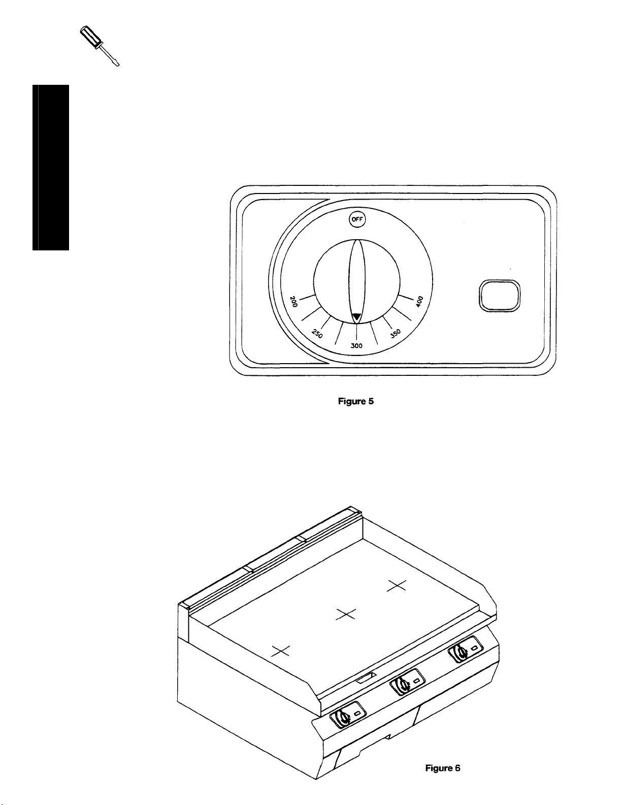
PILOT ADJUSTMENTS:
A. Remove the pilot adjust cover screw located at the
pilot gas outlet on safety valve. Refer to Figure 4.
B. Using a screwdriver, turn pilot adjusting screw to the
right to decrease or left to increase the size of the pilot
flame. (Flame should cover thermocouple tip,
approximately 1/2".)
C. Replace pilot adjustment cover screw.
BURNER ADJUSTMENTS:
A. Turn burner valve to full ON position. (NOTE: If
griddle is cold, wait 5 minutes before making
adjustments.)
B. Loosen screw which holds the sheet metal air shutter.
C. If the flame is blowing or lifting off the burner ports,
close air shutter on front of burner until a stable
flame is obtained.
D. If the flame is yellow tipping, open the air shutter until a stable flame is obtained.
E. Tighten the set screw which holds the air shutter.
SECTION THREE — SERVICE
COUNTER GRIDDLE
PAGE 1
Page 22
ADJUSTMENTS
Litho in U.S.A.
COUNTER GRIDDLE SECTION
THERMOSTAT CALIBRATION
A. To Check Calibration:
1. Turn thermostats to the
300°F marking. See
Figure 5.
SERVICE
2. After burners have been on a minimum of 1 hour (if cold or 30 minutes if already hot when set at 300°F) place a reliable
thermometer or thermocouple with test instruments in the center of the griddle and over the center of each burner. See
Figure 6.
3. Continue to check temperatures at 5 minute intervals, until you have two readings that are within 30° of each other.
4. The control should only be recalibrated if your reading is not within 30 degrees of the dial setting (300°F).
THREE — SERVICE
PAGE 2
2-94
Page 23

ADJUSTMENTS
B. To Recalibrate Thermostat:
This control has been carefully calibrated at the factory. That is, it is so adjusted to match the actual
griddle temperatures. Field calibration is seldom necessary and it should NOT be done unless considerable
experience with cooking and temperatures definitely proves that the control is not maintaining the temperatures to
which the dial is set.
1. When recalibrating, check temperatures as instructed in previous section.
2. Set temperature indicator knob to 300°F marking.
3. Remove indicator knob j from dial stem kand insert dial stem k back on thermostat. Refer to Figure 7.
SERVICE
4. Insert screwdriver through center of dial stem k into the calibration stem slot land push calibration stem l
inward. NOTE: DO NOT TURN SCREW ON CALIBRATION STEM.
5. While holding calibration stem l in with screwdriver, look for indicator mark m on dial stem k. Refer to Figure
7A.
6. Locate indicator mark that points closest to 300°F.
7. Rotate this indicator mark untill it points to the actual temperature you are reading off of the temperature
sensing device you placed in center of grill.
8. Release pressure on calibration stem l.
9. Reinstall knob l and turn thermostat to 300°F and check temperature again at 5 minute intervals.
10. If the griddle will not adjust to within 30°F this means that the sensing bulb is inoperative and the control
should be replaced.
COUNTER GRIDDLE
SECTION THREE — SERVICE
PAGE 3
Page 24

SERVICE
Litho in U.S.A.
TROUBLE SHOOTING:
Problem Look for Unit will not heat up - Main gas supply is "OFF"
Burners produce excessive carbon deposits - Incorrect gas type or orifice size
SERVICE
Pilot produces excessive carbon deposits - Pilot gas not adjusted properly
Burner will not come on - Safety valve in "Pilot" position
Pilot will not stay lit - Pilot was not adjusted properly
COUNTER GRIDDLE SECTION
THREE — SERVICE
PAGE 4
- Pilot not lit
- Safety valve not "ON"
- Incorrect supply pressure
- Incorrect burner air mixer adjustment
- Burner orifice out of alignment with burner
- Incorrect orifices
- Incorrect pilot orifice
- Pilot out
- Clogged burner - charge ports
- Clogged or dirty orifice
- Draft condition
- Improper ventilation systems
- Air in gas line
- Valve end of thermocouple corroded or loose
- Pilot shield needs to be moved closer to pilot
- Improper gas pressure
- Incorrect gas supply size (not enough volume)
2-94
Page 25

COUNTER GRIDDLE
PARTS
PARTS
WARNING
INSTALLATION OF OTHER THAN GENUINE SOUTHBEND PARTS WILL VOID THE
WARRANTY OF THIS EQUIPMENT.
The serial plate is located behind the front panel, on inside right lining. There is also an Identification Plate mounted on
the left side of the front valve panel that will supply model and serial number.
Replacement parts may be ordered either through a Southbend Authorized Parts Distributor or a Southbend Authorized
Service Agency.
When ordering parts, please supply the Model Number, Serial Number, Part Number, Description, plus Finish, Type of
gas and Electrical Characteristics as applicable.
For parts not listed, consult a Southbend Authorized Parts Distributor or Southbend Authorized Service Agency. If
necessary, please consult Southbend Parts Department for assistance.
Models: SG-24,SG-24E
SG-36, SG-36E
SG-48, SG-48E
SG-60, SG-60E
SG-72, SG-72E
Suffix "E" indicates Electronic Ignition.
REPLACEMENT PARTS INDEX: see pages
Legs and Insulated Bases 2
Manifold and Runner Tube Parts 3
Body Parts SG Series 4-5
Thermostat Pilots and Controls 6-7
Rear Gas Piping and Regulators 8
Electronic Ignition Parts 9
Wiring Diagram For "E" Suffix 10
COUNTER GRIDDLE
SECTION FOUR — PARTS
PAGE 1
Page 26

PARTS
LEG AND INSULATED BASES
ITEM PART NO. DESCRIPTION 24 36 48 60 72
1 1163561 4" Leg (single) 4 4 4 8 8
2 1173884 Insulator Front 24" 1
3 1173883 Insulator Side 2 2 2 2 4
* 1173888 Insulator Base Assembly 1
* 1173889 Insulator Base Assembly
* 1173890 Insulator Base Assembly
* 1173891 Insulator Base Assembly
+ 1146304 Screw #10x1/2 Truss Head 4 4 4 4 8
1173885 Insulator Front 36"
1173886 Insulator Front 48"
1173887 Insulator Front 60"
1172857 Set of 4 Legs 1 1 1 1 2
1
1
• Includes 2 Sides — 1 Front and 4 Screws.
• + Not shown.
COUNTE GRIDDLE Litho in U.S.A.
SECTION FOUR- PARTS 2-94
PAGE 2
1
1
1
1
2
Page 27

PARTS
MANIFOLD AND RUNNER TUBE PART
ITEM PART NO. DESCRIPTION 24 36 48 60 72
1 1174358 Runner Tube Assembly 24" 1
2 1174374 Manifold Pipe Weld Assembly 24" 1
3 1058468 Orifice Spud, NAT 1
4 1147007 Pipe Plug 1/8" 1 1 1 2 2
1174362 Runner Tube Assembly 36"
1174364 Runner Tube Assembly 48"
1174378 Manifold Pipe Weld Assembly 36"
1174382 Manifold Pipe Weld Assmembly48"
1058465 Orifice Spud, NAT
1058456 Orifice Spud, NAT
1058474 Orifice Spud, Propane 1
1058470 Orifice Spud, Propane
1058468 Orifice Spud, Propane
1
1
1
1
1
1
1
1
1
1 2
1
1 2
1
1 2
1
1 2
COUNTER GRIDDLE
SECTION FOUR — PARTS
PAGE 3
Page 28
PARTS
COUNTER GRIDDLE
Litho in U.S.A.
SECTION FOUR — PARTS
PAGE 4
2-94
Page 29

PARTS
BODY PARTS SG SERIES
ITEM PART NO. DESCRIPTION SG 24 SG 36 SG 48 SG 60 SG 72
1 1174443-01 Griddle Assembly 24" 1
1 1174445-01 Griddle Assembly 36"
2 1172224 Grease Chute Weld Assembly 1 1 2 2 2
3 1174415 Control Panel Assembly 24" 1
4 1174417 Poly Cover Thermostat 2 3 4 5 6
5 1173690 Body Side Left 1 1 1 2 2
6 1173691 Body Side Right 1 1 1 2 2
7 1166662 Insulation 2 2 2 4 4
8 1173600 Side Liner, Left 1 1 1 2 2
9 1173601 Side Liner, Right 1 1 1 2 2
10 1174410 Rue Riser Front, 24" 1
11 1174402 Flue Riser Side 2 2 2 4 4
12 1174409 Flue Riser Center Support 1 2 3 5 6
13 1174403 Flue Riser Back, 24" 1
14 1174398 Grease Drawer Assembly 1 1 2 2 2
15 1174395 Lower Cover, Side 2 1 2 3 2
16 1174396 Lower Cover, Side Right 36"
17 1174466 Lower Cover Support, Left 1 1 2 2 2
18 1174394 Lower cover Support, Right 1 1 2 2 2
19 1174670 Grease Drawer Slide 2 2 4 4 4
20 1174350 Bottom Main 24" 1
21 1173676 Body Bottom Back, 24" 1
22 1174348 Leg Support, Right 1 1 1 2 2
23 1174346 Leg Support, Left 1 1 1 2 2
24 1174470 Body Bottom Support
25 1174440 Grease Chute Support 1 1 2 2 2
26 1174367 Top Front Support, 24" 1
27 1174468 Flue Diverter 2 3 4 5 6
28 1174357 Burner Rest 2 3 4 5 6
29 1174356 Burner Divider 1 2 3 3 4
30 1174353 Burner Box Bottom, 24" 1
1174355 Burner Box Bottom, 48" 1
1174447-01 Griddle Assembly 48"
1174449-01 Griddle Assembly 60"
1174451-01 Griddle Assembly 72"
1174419 Control Panel Assembly 36"
1174421 Control Panel Assembly 48"
1174411 Rue Riser Front, 36"
1174412 Flue Riser Front, 48"
1174413 Flue Riser Front, 60"
1174414 Flue Riser Front, 72"
1174405 Flue Riser Back, 36"
1174407 Flue Riser Back, 48"
1174397 Lower Cover, Center 48"
1174351 Bottom Main 36"
1174352 Bottom Main 48"
1173678 Body Bottom Back, 36"
1173680 Body Bottom Back, 48"
1174368 Top Front Support, 36"
1174369 Top Front Support 48"
1174354 Burner Box Bottom, 36"
1
1
1
1
1
1
1
1 1 2 2
1
1
1
1
1
1
1
1
1
1
1
1
1 2
1
1
1 2
1 2
1
1 2
1
1 2
1
1 2
1
1 2
COUNTER GRIDDLE
SECTION FOUR — PARTS
1
1
Page 30
PARTS
Litho in U.S.A
COUNTER GRIDDLE
SECTION FOUR — PARTS
PAGE 6
2-94
Page 31

PARTS
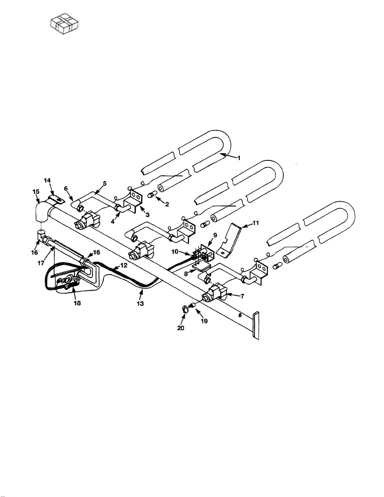
THERMOSTATS. PILOTS AND CONTROLS
ITEM PART NO. DESCRIPTION
1 1174341 "J"BURNER 2 3 4 5 6
2 1008737 Hood Orifice, NAT 2 3 4 5 6
1008752 Hood Orifice, Propane 2 3 4 5 6
3 1174370 Orifice Support Bar 2 3 4 5 6
4' 1148306 Orifice Body Fitting 2 3 4 5 6
5 1174393 Tube 3/8 Manifold to T Stat 2 3 4 5 6
6 1166150 Brass Elbow 2 3 4 5 6
7 1174337 Griddle Thermostat 2 3 4 5 6
8 1174366 Pilot Bracket 1 1 1 2 2
9 1173574 Pilot Body 1 1 1 2 2
10 1174423 Pilot Orifice, NAT 1 1 1 2 2
1174424 Pilot Orifice, Propane 1 1 1 2 2
11 1174467 Pilot Shield 1 1 1 2 2
12 1174371 Tube 1/4" Pilot to Safety 1 1 1 2 2
13 1161521 Thermocouple 36" Long 1 1 1 2 2
14 1173700 Manifold Pipe Support 1 1 1 2 2
15 1174384 Manifold Elbow Weld Assembly 1 1 1 2 2
16 1160008 Brass Elbow 2 2 2 4 4
17 1174392 Tube 5/8 Feed to Manifold 1 1 1 2 2
18 1174340 Combination Safety Valve 1 1 1 2 2
19 1174338 Thermostat Dial Stem 2 3 4 5 6
20 1173645 Indicator Knob 2 3 4 5 6
SG
24
SG
36
SG
48
SG
60
SG
72
* 1148306 Jam Nut Used with Orifice Body Fitting 2 3 4 5 6
COUNTER GRIDDLE
SECTION FOUR — PARTS
PAGE 7
Page 32

PARTS
COUNTER GRIDDLE
Litho in U.S.A.
For Rear Gas Connection
SECTION FOUR — PARTS
PAGE 8
SG REAR GAS PIPING AND REGULATOR
ITEM PART NO. DESCRIPTION
1 1147305 Pipe TEE 3/4" x 3/4" x 1/2"
2 1167381 Pipe Nipple 3/4" x 7" 1 1 1 1 1
3 1174594 Tee Plate Weld Assembly 1 1 1 2 2
4 1147011 Pipe Plug 3/4" 1 1 1 2 2
5 1147116 Bushing 3/4" x 1/2" 1 1 1 3 3
6 P9158 Brass Connector 1/2 x 5/8cc 1 1 1 2 2
7 1174601 Upper Tube 1 1 1 2 2
8 1174389 Cross Feed Tube - - - 1 1
9 1160205 Regulator NAT Gas 1 1 1 1 1
10 1146801 Pipe Nipple 1"x 2" 0 0 0 1 1
1160206 Regulator Propane Gas 1 1 1 1 1
SG
24
SG
36
SG
48
SG
60
1 1
SG
72
2-94
Page 33
PARTS
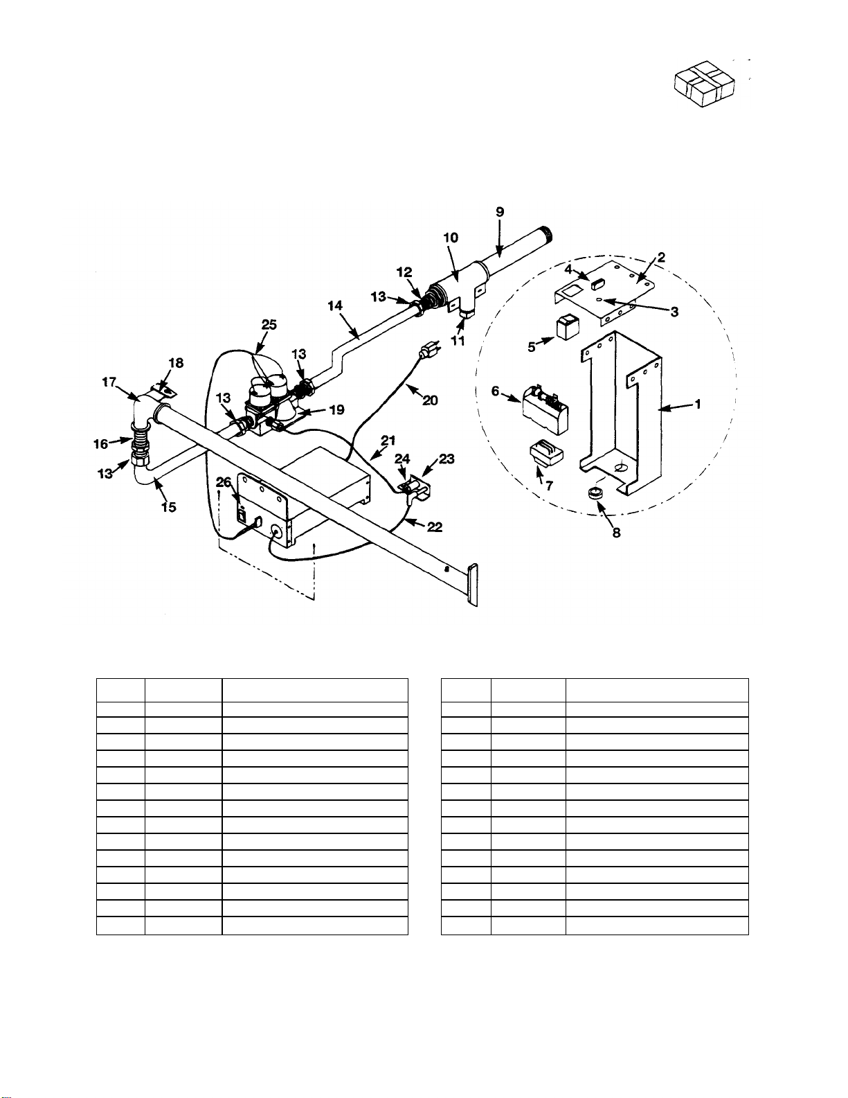
SGE ELECTRONIC IGNITION PARTS - USED ON ALL MODELS WITH SUFFIX "E"
ITEM PART NO. DESCRIPTION ITEM PART NO. DESCRIPTION
1 1174807 Control Box Body 15 1174812 Tube 5/8" (90 Degrees)
2 1174806 Control Box Front 16 1146803 Nipple Black 3/4" x 3"
3 1161675 Wire Snap Bushing 1/2" 17 1174384 Manifold Elbow Weld Assembly
4 1165699 Plug, Nylon, 94V-2 4 Pin 18 1173700 Manifold Pipe Support
5 1170343 Rocker Switch DPST (ON-OFF) 19 1174810 Dual Pilot Valve w/Solenoid
6 1174813 Spark Ignition Pilot Module 20 1162957 Molded Plug and Cord
7 1172277 Transformer 21 1174808 Tube 1/4" (Pilot)
8 1172285 Strain Relief Bushing 22 1174817 Spark Ignition Cable
9 1167381 Black Pipe Nipple 3/4" x 7" 23 1174814 Spark Ignition Pilot
10 1174594 Tee Plate Weld Assembly 24 1174423 Pilot Orifice, NAT
11 1147011 Pipe Plug Black 3/4"
12 1147116 Bushing 3/4" to 1/2" 25 1174822 Wire Bundle
13 P9158 Connector Brass 1/2m x 5/8cc 26 1163054 Adhesive Label "ON"
14 1174809 Tube 5/8" (Offset)
1174424 Pilot Orifice, Propane
* 1174815 Spark Ignition Schematic
* Not Shown on Diagram.
COUNTER GRIDDLE
SECTION FOUR — PARTS
PAGE 9
Page 34

PARTS
COUNTER GRIDDLE
Litho in U.S.A.
SECTION FOUR — PARTS
PAGE 10
2-94
Page 35

A MIDDLEBY COMPANY
Convection Ovens Ranges Steam Kettles Under Fired Broilers
Cook & Hold Convection Ovens Fryers Tilting Braising Pans Salamander Broilers
Bake & Roast Ovens Special & Custom Equipment Cooker/Mixer Kettles Cheese Melters
Pizza Ovens Convection Steamers Floor Model Broilers Counter Top Broilers & Griddles
Page 36
COUNTER GRIDDLE
1100
Old Honeycutt
PART NUMBER
1174442
- 2-94
A product with the Southbend name incorporates the best in durability and low
maintenance. We all recognize however, that replacement parts and occasional
professional service may be necessary to extend the useful life of this unit.
When service is needed, contact a Southbend Authorized Service Agency, or
your dealer. To avoid confusion, always refer to the model number, serial
number, and type of your unit.
Road Fuquay.NC 27526
(919)552-9161 FAX
(919) 552-9798
(800)348-2558
 Loading...