

Page 1
Installation & Operations Manual
Oven - Smoker
SB-5-ES / SB-10-ES
IMPORTANT FOR FUTURE REFERENCE
Please complete this information and retain
this manual for the life of the equipment:
Model #: __________________________
Serial #: __________________________
Date Purchased: ___________________
WARNING
Improper installation, adjustment, alteration, service, or maintenance can cause property damage, injury, or death.
Read installation, operation, and maintenance instructions thoroughly before installing or servicing this equipment.
1100 Old Honeycutt Road, Fuquay-Varina, NC 27526 USA • www.Southbend nc.com
MANUAL 1188200 REV 0 (12/06)
$30.00
OVEN / SMOKER
Page 2

SAFETY PRECAUTIONS OVEN / SMOKER
SAFETY PRECAUTIONS
Before installing and operating this equipment, be sure everyone involved in its operation is fully trained and aware of
precautions. Accidents and problems can be caused by failure to follow fundamental rules and precautions.
The following symbols, found throughout this manual, alert you to potentially dangerous conditions to the operator,
service personnel, or to the equipment.
WARNING
FOR YOUR SAFETY, DO NOT STORE OR USE GASOLINE OR
OTHER FLAMMABLE VAPORS AND LIQUIDS IN THE VICINITY OF
THIS OR ANY OTHER APPLIANCE.
WARNING
Improper installation, adjustment, alteration, service, or
maintenance can cause property damage, injury, or death. Read the
installation, operating, and maintenance instructions thoroughly
before installing or servicing this equipment.
NOTICE
Contact your authorized Service Agency to perform maintenance and repairs.
NOTICE
Using any parts other than genuine Southbend factory-manufactured parts relieves the
manufacturer of all warranty and liability.
NOTICE
Southbend (Manufacturer) reserves the right to change specifications at any time.
KEEP THIS MANUAL IN A VISIBLE LOCATION NEAR THE OVEN FOR FUTURE
REFERENCE.
Copyright © 2006 by Southbend . All rights reserved. Published in the United States of America.
PAGE 2 OF 24 INSTALLATION & OPERATIONS MANUAL 1189200 REV 0 (12/06)
Page 3

INTRODUCTION
Congratulations! You have purchased one of the finest pieces of heavy-duty commercial cooking equipment on the
market.
You will find that your new equipment, like all Southbend equipment, has been designed and manufactured to meet
the toughest standards in the industry. Each piece of Southbend equipment is carefully engineered and designs are
verified through laboratory tests and field installations. With proper care and field maintenance, you will experience
years of reliable, trouble-free operation. For best results, read this manual carefully.
RETAIN THIS MANUAL FOR FUTURE REFERENCE.
This manual is for the Southbend Oven/Smoker. Read these instructions carefully before attempting installation.
Installation and initial startup should be performed by a qualified installer. Unless the installation instructions for this
product are followed by a qualified service technician (a person experienced in and knowledg eable of the installation
of commercial gas and/or electric cooking equipment) then the terms and conditions on the Manufacturer’s Limited
Warranty will be rendered void and no warranty of any kind shall apply.
In the event you have questions concerning the installation, use, care, or service of the product, contact:
Southbend Technical Service
1100 Old Honeycutt Road
Fuquay-Varina, North Carolina 27526 USA
919-552-9161
www.Southbend nc.com
SPECIFICATIONS
NOTICE
Local codes regarding installation vary greatly from one area to another. The National Fire Protection Association,
Inc. states in its NFPA 96 latest edition that local codes are the “authority having jurisdiction” when it comes to
installation requirements for equipment. Therefore, installations must comply with all local codes
Southbend reserves the right to change specifications and product design without notice. Such revisions do not
entitle the buyer to corresponding changes, additions, or replacements for previously purchased equipment.
This product is intended for commercial use only, not for household use.
CLEARANCES
There must be adequate clearance between the broiler and adjacent construction due to the heat generated by the
broiler. Clearance must also be provided for servicing and for operation.
The minimum clearance from non-combustible construction is 4” on the sides and 4" on rear (to permit combustion air
to enter the rear of the broiler).
Adequate clearance must be provided in front of the broiler for operation and cleaning.
INSTALLATION & OPERATIONS MANUAL 1189200 REV 0 (12/06) PAGE 3 OF 24
Page 4

ABOUT YOUR EQUIPMENT Oven / Smoker
SOUTHBEND OVEN/SMOKER
Southbend utilizes separate controls in conjunction with the desired air movement to supply the
desired level of heat and moisture. When using both heat and moisture the temperature of the
unit's atmosphere results from a combination of the heat and moisture sources.
Because of the separate controls it is possible to have a number of different conditions:
• Heat, moisture, natural air • Heat, moisture, fan
• Heat, no moisture, natural air • Heat, no moisture, fan
• Moisture, no heat, natural air • Moisture, no heat, fan
By providing separate controls it is possible to obtain any of the above conditions. In addition to
the above conditions, based on normal heat and moisture conditions, the use of a STEAM or
SMOKE option offers other variations.
The Southbend SB-5-ES and SB-10-ES Smokers are electrically powered and generally do
require exhaust hoods. However, the ultimate decision as to hood requirements rests with your
local authorities. The SB-5-ES stands 41" high (45" if installed with the 4" Appliance Legs) while
the SB-10-ES stands 78" high (including the Casters). Each unit is 32½" deep, 23¾" wide and
takes up less than 5½ square feet of your valuable floor space.
The Southbend SB-5-ES and SB-10-ES are equipped with a positioned air flow system. This
system allows the heated air and/or smoke to circulate completely and evenly around the interior
of the SB-5-ES or SB-10-ES for a uniform and consistent product without having to turn pans. All
processed product can be unloaded at the same time, allowing you to concentrate on things of
more importance without having to remember if and when to turn pans in your smoker.
The SB-5-ES or SB-10-ES can be used to cook, steam or smoke the following products:
• Meats • Fish
• Potatoes • Fowl
• Bacon • Vegetables
All units in this series are designed for the following:
• Automatic pan positioning • Dependability
• Rapid, even processing • Low energy consumption
• Easy cleaning • Low maintenance
• Simple operation • Rapid servicing
The Southbend SB-5-ES has a capacity of up to six (6) full-sized 18" x 26" sheet pans. The SB10-ES has a capacity of thirteen (13) 18" x 26" full-size pans. These pans are supported by
chromed Side Racks to provide a 3½" vertical spacing between pans. Smoke is generated in the
Smoke Box attached to the back wall of the Oven interior, or in the optional side-mounted External
Smoke Box.
Supplemental moisture can be added through the AUTOMIST Humidity System. The AUTOMIST
system adds moisture by injecting a water mist into the Blower Wheel for circulation throughout
the Oven cavity. This water injection is controlled by a Repeat Cycle Timer with a fixed "OFF" time
and a variable "ON" time. The "ON" time is adjusted by setting the Humidity Control on the front of
the unit. A higher setting on the Control allows for a longer water spray in the Oven, resulting in
higher moisture levels.
PAGE 4 OF 24 INSTALLATION & OPERATIONS MANUAL 1189200 REV 0 (12/06)
Page 5

An optional Programmable Control is also available for the SB-5-ES and SB-10-ES. The
Programmable Control allows you to set and run specific programs as menus complete and total
control of your production program.
A Meat Probe is also available for either Manual or Programmable Control units. The Meat Probe
allows you to use the internal temperature of your product to control the operation of the SB-5-ES
or SB-10-ES. When used with the Hold feature of the Smoker you can load your product in the
morning (or the night before) and not bother with it again until you are ready to use it.
AVAILABILITY FOR TESTING:
A prospective customer may see a unit in operation as follows:
• At an existing installation
• At a dealer's showroom
• At the Southbend manufacturing facility
If contacted, Southbend will provide the information on the nearest location. In the event that a
customer desires to test a unit at his place of business, arrangements can be made based on a
specifically defined program. In the event that a customer wants to try a special product,
arrangements can be made to determine what conditions are necessary for baking so the
customer can determine the suitability for his program.
COMPARISON WITH OTHER UNITS:
Southbend will provide test data or a test unit for the comparison of results with any other unit on
the market; however, Southbend reserves the right to have its designated representatives
available during the test. All results of such comparison tests will be made available to Southbend
and may be used by Southbend. As stated previously, Southbend operating costs compare
favorably with gas convection ovens and our ovens generally do not require hoods. Based on
production of consistent quality products from the Southbend Oven, as well as baking times,
Southbend out-performs the competition.
CONSTRUCTION:
All combination Ovens in this series are constructed of stainless steel inside and outside. All of the
frame members are welded to provide long life construction. Components such as temperature
and humidity controls, timers, switches, motors, heating elements and other such items are
thoroughly tested before shipment. On-going research and development projects are used to
introduce the latest and most dependable parts.
SHIPMENT:
Southbend units are usually shipped directly from the factory or delivered from a dealer, unless
sold at a show or after a test or demonstration. Unless otherwise agreed to by Southbend , freight
is paid by the buyer F.O.B. from the Southbend manufacturing facility in Menominee, Michigan.
Shipping time varies, depending upon the shipping point, the time of year, and shippers used.
Usually Southbend prefers three weeks lead time, but can reduce the time, in some instances, on
an emergency basis.
Southbend employs accepted packaging standards to ensure that your equipment arrives in
excellent condition. However, damage may still occur through negligent handling or accident on
the part of the shipping company. Southbend works closely with all of its customers in tracing
shipments to delivery and to minimize handling.
INSTALLATION & OPERATIONS MANUAL 1189200 REV 0 (12/06) PAGE 5 OF 24
Page 6

OPERATING INSTRUCTIONS OVEN / SMOKER
RECEIPT AND INSTALLATION
RECEIPT:
IMMEDIATELY INSPECT FOR SHIPPING DAMAGE
All containers should be examined for damage before and during unloading. The freight carrier has assumed
responsibility for its safe transit and delivery. If damaged equipment is received, either apparent or concealed, a
claim must be made with the delivering carrier.
Apparent damage or loss must be noted on the freight bill at the time of delivery. The freight bill must then be
signed by the carrier representative (Driver). If the bill is not signed, the carrier may refuse the claim. The carrier
can supply the necessary forms.
A request for inspection must be made to the carrier within 15 days if there is concealed damage or loss that is
not apparent until after the equipment is uncrated. The carrier should arrange an inspection. Be certain to hold all
contents plus all packing material.
A. Inspect the entire perimeter of the package for damage or punctures to the packing material.
This may indicate damage to the unit inside. Call any and all packing damage to the
attention of the delivery person.
B. If any packing damage is found uncrate the unit immediately in the presence of the delivery
person to determine if the unit is damaged. If any damage is found indicate the type and
amount of damage on the shipping documents and notify Southbend at (919) 552-9161
immediately after filing a freight claim.
C. Uncrate the unit carefully and check the entire unit (top, front, back and both sides) for any
visible or hidden damage.
D. Remove the unit from the shipping pallet and inspect the bottom for any damage.
E. If any damage is noted after the driver leaves immediately contact t he freight company and
Southbend.
F. Check each Oven Door. Make sure the Door closes completely, and that the Door Gasket
seals firmly. If the Gasket does not seal correctly please contact the Southbend Service
Department for instructions and assistance in any required adjustments.
INSTALLATION:
A. Check to determine that the power source is the same voltage and phase as that indicated
on the label on the side of the unit.
B. If you have received an SB-5-ES you should attach the included Appliance Legs to the
bottom of the unit. Each Leg stud screws into a th readed h ole in each corner of the base.
C. Position the unit wher e it is to be oper ated and adjust the Applianc e Legs of the SB-5-ES so
the unit stands level and solid. If you have an SB-10-ES you may need to use metal shims
under the Casters to level the uni t.
D. For the SB-5-ES: Make sure the GREASE PAN is installed inside the bottom of the unit. This
PAN will catch most of the drippings from your product as it is processed, making clean-up
that much easier.
For the SB-10-ES: Make sure the GREASE PAN is installed beneath the unit. This PAN will
catch the liquid that accumulates in the bottom of the unit while you are processing your
product.
E. Carefully set all Controls and Switches to their OFF positions.
PAGE 6 OF 24 INSTALLATION & OPERATIONS MANUAL 1189200 REV 0 (12/06)
Page 7
OVEN / SMOKER INITIAL START-UP
ELECTRICAL CONNECTIONS
F. Install the water supply if your unit was ordered with the optional AUTOMIST feature (refer to
WATER SUPPLY CONNECTION on the following page).
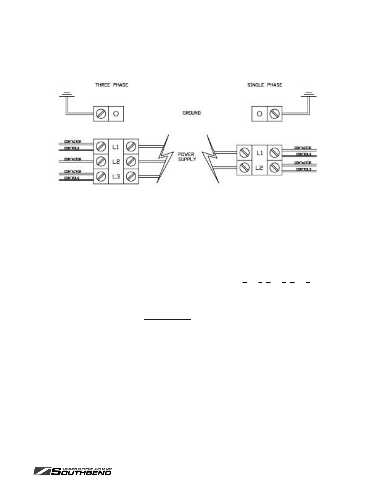
G. The installing technician or electrician should complete the electrical connections by
removing the Outside Top of the unit (this panel is pressed onto the top of the unit and
should lift off easily). Connect the unit to the available power supply either through an
attached cord and receptacle or through direct wiring by following these steps:
1.Take note of the labeling on the Power Terminal Block (Line 1, Line 2, Line 3, ).
2.Carefully identify the power source leads and attach them to the appropriate terminal
connections. Make sure all connections are clean and tight.
3.Properly ground the unit BEFORE USE by attaching a grounding wire to the Ground Lug
or Clamp provided next to the Power Terminal Block.
4.Allow enough slack in the wiring to allow for equipment to be moved about during
installation and any future servi cing .
H. Check the voltage at the terminals on the Power Terminal Block with a voltmeter and
compare the values with the label listings on the side of the Oven. If the values match the
unit is ready for its INITIAL START–UP. If the readings DO NOT coincide you must call the
Southbend Service Department for instructions on changing the voltage and/or the phase.
I. Carefully position the Outside Top on the unit but do not press it into place. Position the unit
in its final operating location and refer to the appropriate INITIAL START–UP PROCEDURE
for your Smoker.
INSTALLATION & OPERATIONS MANUAL 1189200 REV 0 (12/06) PAGE 7 OF 24
Page 8

OPERATING INSTRUCTIONS OVEN / SMOKER
IMPORTANT: FAILURE TO FOLLOW THESE INSTRUCTIONS, FAULTY
INSTALLATION OR IMPROPER USE MAY CAUSE SEVERE EQUIPMENT
DAMAGE OR PERSONAL INJURY, AND MA Y A LSO VOID ALL OR PART
OF YOUR Southbend EQUIPMENT WARRANTY!!!
WATER SUPPLY CONNECTION:
IMPORTANT: Southbend strongly recommends that SOFT WATER only be used in any unit
requiring a water supply. Also, a good quality water filter MUST be installed in-line between the unit
connection and the water supply to guard against clogging and mineral build-up in the components.
This is extremely important in areas having hard water. This filter may be installed at the water
source or adjacent to the Water Inlet Fitting on the Smoker, whichever is more convenient for you.
This equipment is to be installed to comply with the federal, state and local plu mbing codes having
jurisdiction.
To correctly install a water supply to your SB-5-ES or SB-10-ES Smoker:
A. Run the correct size tubing from the water supply to the unit's location; this tubing should be at
least as big as the Water Inlet Fitting (¼") on the back of the unit. Allow some slack for final
unit positioning and service. Avoid any kinks or strains on the tubing and place the tubing
where it will not be damaged in any way.
B. The tubing end that attaches to the back of the Smoker must not be damaged or deformed in
any way. The cut end should be cut straight and clean with no deforming of the tubing. All
burrs and sharp edges should be removed to ensure a proper and leak-free connection.
C. Position the tubing so that the tubing runs straight into the Water Inlet Fitting. Be careful not to
kink the tubing if you bend it, and do not bend the tubing within two (2) inches of the end.
D. The two-part compression fitting (tapered coll ar and nut) is placed approximately 1" onto the
tubing so that the collar is inside of the nut and the threaded opening of the nut is toward the
Water Inlet Fitting.
E. Push the tubing all the way into the Water Inlet Fitting (approximately ¼") and hold it there
while you thread the compression nut onto t he Water Inlet Fitting. Us e an open-end wrench
to slowly tighten the compression nut until it is just snug, but d o not over-tighten t he fitting! If
the joint leaks when tested and further gentle tightening does not stop the leak the two-part
compression fitting mu st be replac ed .
Careful attention to these simple procedures will help to ensure an installation without leaks.
If you have any questions or problems please call the Southbend Service Department at
(919) 552-9161.
PAGE 8 OF 24 INSTALLATION & OPERATIONS MANUAL 1189200 REV 0 (12/06)
Page 9

OVEN / SMOKER INITIAL START-UP
IMPORTANT: Please install any required drainage plumbing at this time. Any required drain
line must be properly installed before attempting an INITIAL START–UP and Operational
Check.
* * * NOTICE * * *
NATIONAL SANITATION FOUNDATION GUIDELINES REQUIRE THAT
ALL INTERIOR PARTS BE REMOVABLE WITHOUT THE USE OF TOOLS.
THIS EQUIPMENT HAS BEEN FACTORY ASSEMBLED TO SAFELY
ACCOMMODATE ROUGH HANDLING THROUGH SHIPMENT AND
ORIGINAL INSTALLATION. AFTER ANY MAINTENANCE, CLEANING OR
REQUIRED SERVICE WORK THE INTERIOR SHEET–METAL PARTS
SHOULD BE REASSEMBLED AND FASTENED HAND–TIGHT ONLY, BUT
STILL REMAIN TIGHT ENOUGH TO PREVENT ANY RATTLE OR
MOVEMENT OF PARTS.
IMPORTANT: THIS UNIT NEEDS TO BE INSTALLED WITH ADEQUATE
BACKFLOW PROTECTION TO COMPLY WITH APPLICABLE FEDERAL,
STATE AND LOCAL CODES.
IMPORTANT: THIS UNIT REQUIRES A SCREEN OF AT LEAST 100 MESH
TO BE INSTALLED IMMEDIATELY UPSTREAM OF ALL CHECK VALVE
TYPE BACKFLOW PREVENTERS USED FOR WATER SUPPLY
PROTECTION. THE SCREEN SHALL BE ACCESSIBLE AND REMOVABLE
FOR CLEANING OR REPLACEMENT.
INSTALLATION & OPERATIONS MANUAL 1189200 REV 0 (12/06) PAGE 9 OF 24
Page 10

OPERATING INSTRUCTIONS OVEN / SMOKER
INITIAL START–UP
(MANUAL CONTROLS)
This START–UP procedure is used to verify that your Southbend SB-5-ES or SB-10-ES Smoker has
been installed correctly and will perform as intended when put into use. This INITIAL START–UP
procedure should be carried out by your electrician, licensed installer or a Southbend approved
service agency. Please read completely through all of this Manual Control START–UP procedure
before beginning.
This procedure includes all optional manual features for the SB-5-ES and SB-10-ES. If your unit does
not include one of these features you can skip over that step in the START–UP procedure.
Manual Controls
! Verify that the electrical and any optional water supplies have been correctly installed.
! Attach the 1" Vent to t he stainless steel vent pipe on top of the unit. Leave the Vent in the
OPEN position (handle vertical).
! Make sure all controls and switches are in their OFF positions and engage the main
electrical and water supplies.
! Set the POWER switch to ON. The red indicator light should illuminate.
! Set the FAN switch to ON. The red indicator light should illuminate and the Blower Wheel
begins to turn.
! Set the 24–HOUR TIMER to 2 hours time.
! Set the HOLD control to 100°F. The red indicator light should not light up.
! Set the COOK control to 150°F. The red indicator light should illuminate and the HEATING
ELEMENTS should begin to heat the Smoker.
! Reset the 24–HOUR TIMER to 0. The COOK control should stop (its red indicator light will
go out) and the HOLD control should activate (the red indicator light will illuminate).
! Set the 24–HOUR TIMER to OFF. The HOLD control should stop (its red indicator light will
go out). The COOK control should also be deactivated (the red indicator light will not
illuminate).
! Set the COOK control and the HOLD control to their OFF positions.
PAGE 10 OF 24 INSTALLATION & OPERATIONS MANUAL 1189200 REV 0 (12/06)
Page 11

OVEN / SMOKER INITIAL START-UP
! Set the HUMIDITY control to #10 and open the DOOR. Water should be sprayed into the
BLOWER WHEEL in short intermittent bursts about 45 seconds apart.
! Set the HUMIDITY control to #3. The length of each water spray should decrease.
! Set the HUMIDITY control to the OFF position.
! Set the SMOKER switch t o the ON position. The SMOKE BOX should begin to heat up. The
standard SMOKE BOX is located ne ar the ceiling on the inside back wall of t he Smo ker; th e
optional EXTERNAL SMOKE BOX is mounted on the side of the unit. (NOTE: It may take a
few minutes for this heat to be felt through the m etal o f the SM OKE B OX.)
! Set the SMOKER switch to the OFF position and close the DOOR.
! Set the 60–MINUTE TIMER to 20 minutes, then turn it down to 5 minutes. The BUZZER
should sound when the TIMER reaches 0.
! Set the 60–MINUTE TIMER to OFF to silence the BUZZER.
! Set the COOK control to 150°F with the 24–HOUR TIMER in the OFF position. The red
COOK indicator light should not illuminate. Set the PROBE control to 100°F and the PROBE
switch to its ON position. The red PROBE and COOK indicator lights should illuminate. As
soon as the Oven interior temperature reaches the PROBE control setting (100°F) the
PROBE indicator light should go out and the COOK control should de-activate. Set the
PROBE switch to its OFF position.
! Set the 24–HOUR TIMER to 0, the HOLD control to 200°F, and leave the COOK control set
at 150°F. The red HOLD indicator light should illuminate. Set the PROBE switch to its ON
position and the PROBE control to 125°F. The red PROBE indicator light should illuminate,
the red COOK indicator light should illuminate, and the red HOLD indicator light should go
out. When the Oven interior temperature reaches t he PROBE con trol sett ing ( 125°F) the red
PROBE control indicator light should go out, the red COOK control indicator light should go
out, and the red HOLD control indicator light should illuminate.
! Return all switches and controls to their OFF positions.
! Clean the SB-5-ES or SB-10-ES both inside and out according to all local and regional
health codes.
YOUR MANUALLY CONTROLLED Southbend SB-5-ES OR ES–13
SHOULD NOW BE READY FOR FULL OPERATIONS.
INSTALLATION & OPERATIONS MANUAL 1189200 REV 0 (12/06) PAGE 11 OF 24
Page 12

OPERATING INSTRUCTIONS OVEN / SMOKER
OPERATING INSTRUCTIONS
The Southbend SB-5-ES or SB-10-ES Smoker is designed to offer maximum flexibility for different
products. Cooking time can be pre-set or determined by the internal temperature of the product
through use of the Probe attachment in either Manual Control or Programmable Control units.
Manual Control units are equipped with our COOK-N-HOLD feature, allowing you to cook your
product at one temperature and hold it at another. This lets you finis h products quickly, but still hold
them at optimum temperatures to prevent loss of moisture and resulting shrinkage. Programmable
Control units have this feature built in, and can be programmed for better control over your final
product.
The SB-5-ES is equipped with an internal Grease Pan to catch any drippings from your pro d ucts and
to make cleaning easier. The Grease Pan can be lifted out for dumping and cleaning at the end of
the day. The SB-10-ES is fitted with an external Pan that is equipped with small ball casters. This
Grease Pan fits beneath the unit directly under the Drain fitting in the floor of the Smoker. Remove
the drain plug to drain accumulated liquid from the bottom of t he SB-10-ES into the Greas e Pan for
removal and disposal.
Smoke is generated in the Smoke Box located on the back internal wall of the Oven, or in the
optional Smoke Box attached to the side of the unit. This Smoke Box consists of a stainless steel
chip box inside of a stainless steel housing. To use the Smoke Box pieces of wood pre-soaked in
water are loaded into the chip box, the chip box is inserted into the housing, and the Smoke switch is
set to the ON position (or the Programmable Control is set to include a certain smoke level). Heating
Elements contained in the housing will heat the wood, giving off smoke. This smoke is circulated
throughout the Oven cavity by the Motor and Blower Wheel. The strength and duration of the
smoking is controlled by the amount of wood placed in the chip box and by the length of time it is
allowed to burn.
MANUAL CONTROL operation:
1) Set the POWER and FAN switches to their ON positions. Select the correct cooking
temperature for your product on the COOK c ontrol and set the 24–HOUR TI MER to at least
1 hour, allowing the Smoker to preheat.
2) Prepare your product as outlined in your recipe. Load the prepared product into the SB-5-ES
or SB-10-ES at your convenience. After loading your product set the 24–HOUR TIMER to
the desired cooking time.
3) Set the HUMIDITY control if you wish to add moisture to your pr oduct during the processing
cycle.
Manual Controls
PAGE 12 OF 24 INSTALLATION & OPERATIONS MANUAL 1189200 REV 0 (12/06)
Page 13

OVEN / SMOKER Operating Instructions
4) Load the SMOKER BOX with wood if you want to add smoke flavoring and color to your
product. Set the SMOKER switch to the ON position.
5) Set the adjustable top VENT according to your product needs. High moisture products, or
products requiring supplemental moisture from the HUMIDITY control, require the VENT
to be at least partially if not all the way open. Low moisture products can be processed
with the VENT handle closed (horizontal). The VENT can also be used to help regulate
the amount of smoke in the SB-5-ES or SB-10-ES.
6) Set the 60–MINUTE TIMER as a reminder during short cooking or smoking cycles.
7) Remove your product as soon as it is finished and reload the SB-5-ES or SB-10-ES.
Repeat steps #1 through #7 as necessary.
The Manual Control SB-5-ES and SB-10-ES come equipped with our COOK-N-HOLD feature.
COOK-N-HOLD allows you to cook your product at one temperature and then aut omatically hold
it at a reduced temperature. Both the COOK and HOLD controls must be set, along with the 24–
HOUR TIMER, in order for you to utilize this feature.
To use the COOK-N-HOLD feature:
1) Follow steps #1 through #5 as listed above.
2) Set the 24–HOUR TIMER to the required length of processing time your product requires.
3) Set the HOLD control to the temperature you wish your finished product to rem ain at. The
24–HOUR TIMER will automatically shift control of the Oven's temperature from the
COOK control to the HOLD control at the end of the timed processing cycle. Your
product will remain at the set HOLD temperature until the setting is changed or the unit is
turned OFF.
IMPORTANT: Your Southbend SB-5-ES or SB-10-ES is well insulated and will maintain the
original Cook temperature for ½ to 1 hour depending on the product, product density and load
size. The temperature will not instantly drop to the hold setting at the end of the timed Cook cycle.
Plan your Cook temperature, Cook time and Hold temperature accordingly to maintain the best
possible product!!!
Manual Controls
INSTALLATION & OPERATIONS MANUAL 1189200 REV 0 (12/06) PAGE 13 OF 24
Page 14

Operating Instructions OVEN / SMOKER
The Southbend Manual Control SB-5-ES or SB-10-ES may also contain an optional PROBE
feature. This PROBE will allow you to cook your product according to its internal temperature
rather than a timed setting.
To use the PROBE option:
1) Follow the original steps #1 through #5, except set the 24–HOUR TI MER to its maximum
(you will be cooking by internal temperature, not time).
2) Insert the PROBE into the thicke st part of y our p roduc t.
3) Set the PROBE control to the desired internal f inished tem peratur e for the product and set
the PROBE switch to the ON position. The red PROBE control indicator light will
illuminate to show that the PROBE is activated.
4) The SB-5-ES or SB-10-ES will cook your product using the setting on the COOK control.
When the product's internal temperature reaches t he level set on the PROBE control the
PROBE will activate the buzzer. Remove your product as soon as it is finished to prevent
over-cooking, or withdraw the PROBE and re-set the controls to use the COOK-N-HOLD
feature to hold your product at a reduced temperature.
Manual Controls
PAGE 14 OF 24 INSTALLATION & OPERATIONS MANUAL 1189200 REV 0 (12/06)
Page 15

OVEN / SMOKER PARTS
MAINTENANCE AND CLEANING GUIDE
Southbend equipment is designed to last for years of useful service. Careful consideration is
given in selecting components for durability, performance and ease of maintenance. For
example, the Smoker Motor has sealed bearings and never needs to be lubricated.
Southbend equipment is designed for minimum care and maintenance certain steps are require d
by the user for maximum life and effectiveness:
•Proper installation of the equipment.
•Correct application and usage of the equipment.
•Dry-out Procedures performed daily.
•Thorough cleaning on a regular basis.
EQUIPMENT INSTALLATION:
A. Install the Southbend SB-5-ES or SB-10-ES Smoker with adequate clearance around the
unit. This is important for cleaning and maintenance, as well as providing cooling air for
While
the Motor and Controls.
B. The installation must be on a level floor to prevent the Door or Doors from swinging when
left in an open position.
C. The SB-5-ES or SB-10-ES Smoker must be connected to the proper power supply as
indicated on the equipment label.
D. The SB-5-ES or SB-10-ES Smoker must be connected to an approved potable water
supply in accordance with all applicable plumbing codes for your area.
APPLICATION AND USAGE:
The SB-5-ES and SB-10-ES Smokers are designed for the low to medium temperatures normally
found in smoking and/or slow-cooking operations. THEY ARE NOT DESIGNED TO
OPERATE AT HIGH TEMPERATURES FOR LONG PERIODS OF TIME!!! Continuous
operation at maximum temperatures and/or humidity settings may result in premature
component failure.
SMOKER DRY–OUT PROCEDURE:
A. Remove the GREASE PAN. Empty and clean the PAN and set it aside.
B. WIPE UP ANY STANDING LIQUIDS IN THE SMOKER BOTTOM.
C. For Manual Control units:
Set the POWER switch to the ON position. Set the COOK control to 150°F and the HOLD
control to OFF. Set the 24–HOUR TIMER to 2 hours so that the COOK control operates.
For Programmable Control units:
INSTALLATION & OPERATIONS MANUAL 1189200 REV 0 (12/06) PAGE 15 OF 24
Page 16

PARTS OVEN / SMOKER
Press the ON/OFF Key to start the Control. Select and pr ess any programmed Menu Key to
begin running that program. Try to select a program th at does not use added m oistu re or
smoke. Allow the Smoker to heat.
D. Open the VENT completely and leave the Smoker DOOR open about 1" to 2". Allow t he
Smoker to run for approximately 30 minute s.
E. Set the POWER switch to the OFF position (or press the ON/OFF Key to turn OFF the
Programmable Control). Leave the DOOR slightly open (about 1" to 2") while the Smoker
is not in use.
THESE DRY–OUT PROCEDURES MUST BE CARRIED OUT DAILY TO HELP MAINTAIN
YOUR EQUIPMENT IN THE BEST POSSIBLE CONDITION. THE REMOVAL OF ALL
RESIDUAL MOISTURE IN THE EQUIPMENT RETARDS ANY CORROSION OR
DETERIORATION OF THE INSULATION AND ELECTRICAL COMPONENTS AND
EXTENDS THE USEFUL LIFETIME OF YOUR Southbend EQUIPMENT.
CLEANING:
Your Southbend SB-5-ES or SB-10-ES should be cleaned daily and as soon as possible after a
spill has occurred. It is essential to maintain a clean unit, especially if the public views the unit in
your place of business. The following should be used for cleaning:
A. The stainless steel exterior may be cleaned with any good stainless steel cleaner or polish,
or with hot soapy water foll owed by a clear rinse if it is very soiled.
B. The DOOR glass may be cleaned with any good glass-cleaning formula. Be sure to wipe
down the DOOR frame, and to clean the GASKET on the ins ide of the DOOR. Dried-on
debris or heavy soiling can be removed with hot soapy water followed by a rinse with
clean fresh water. Wipe the DOOR dry to prevent spotting. CAUTION: DO NOT USE
ABRASIVE CLEANERS ON THE DOOR OR YOU MAY SCRATCH THE GLASS!!!
C. Remove and clean the chip pan from the SMOKER BOX daily. Dispose of all ashes safely.
Wipe up any standing liquids in the bottom of the Smoker and sweep up any solid
particles of debris.
D. The interior should be cleaned on a regular basis (at least two or three times a week) with
mild soap and hot water followed by a thorough rinse with clean fresh water and a
sanitizing agent; wiping the interior dry will help to prevent water spotting. Water spotting
and other mineral deposits should be removed with any mild mineral removal agent as
soon as they are noticeable.
E. Leave the Smoker DOOR open by about 1" to 2" while the unit is not in use.
PAGE 16 OF 24 INSTALLATION & OPERATIONS MANUAL 1189200 REV 0 (12/06)
Page 17

OVEN / SMOKER PARTS
* * * CAUTION * * *
Southbend DOES NOT RECOMMEND the use of any strong commercial or caustic product on
this equipment. DO NOT allow any type of caustic cleaner to come into contact with any
aluminum parts (such as the Door Frame), the silicon rubber Door Gaskets, or any of the sealant
in the Smoker seams and joints. These caustic compounds may cause discoloration and/or
degradation of these parts, and may result in permanent damage. DO NOT use bleach or bleach
compounds on any chromed parts; bleach may damage chrome plating.
NOTE:
Southbend has had very good results with a product called JIFFY CLEANER. For standard
cleaning simply spray JIFFY on and wipe off. Heavily soiled areas may require a short period of
soaking. This cleaner is available through Southbend (Part #51–0002) or through your local
Rochester/Midland distributor or representative.
INSTALLATION & OPERATIONS MANUAL 1189200 REV 0 (12/06) PAGE 17 OF 24
Page 18

PARTS OVEN / SMOKER
REPLACEMENT PARTS LIST
(SB-5-ES & SB-10-ES)
Reference # Description Replacement Part #
ELECTRICAL COMPONENTS:
1 Power Terminal Block ............................................................................... 50–1332
2 Ground Lug................................................................................................50–1329
3 Control Fuse Assembly ..............................................................................66-1097
4 Contactor:
120v coil.............................................................................................66-2013
240v coil.............................................................................................66-2017
5 Heating Element:
SB-5-ES, 208v, 1000w......................................................................60-0190
SB-5-ES, 240v, 1000w......................................................................60-0191
ES-13, 208v, 2000w..........................................................................60-0192
ES-13, 240v, 2000w..........................................................................60-0193
6 Smoke Box Element Assembly..................................................................47-9241
7 Motor Assy w/Blower Wheel.....................................................................250-1035
8 Water Solenoid Valve:
120v coil.............................................................................................50-0308
240v coil.............................................................................................50-0307
9 Repeat Cycle Timer:
120v ...................................................................................................66-8012
240v ...................................................................................................66-8065
10 Buzzer Alarm:
120v .................................................................................................252-1003
240v ...................................................................................................66-9003
11 Relay (DPDT, 20 amp):
120v ...................................................................................................50-0433
240v ...................................................................................................66-9025
12 Cooling Fan Assembly (4"):
120v .................................................................................................250-3001
240v ...................................................................................................66-9013
13 Thermal Overload S afe ty ( 425°F) ..............................................................66-1015
INTERIOR COMPONENTS
14 Side Rack:
6-Pan................................................................................................101-6013
7-Pan................................................................................................101-7013
15 Shelf101-0025
16 Motor Assy w/ Blower Wheel....................................................................250-1035
17 Water Injection Nozzle (AUTOMIST option)..............................................31-0033
18 Smoker Chip Box......................................................................................100-9218
19 ....Water Pan (1/3 size x 2½")........................................................................50-0074
PAGE 18 OF 24 INSTALLATION & OPERATIONS MANUAL 1189200 REV 0 (12/06)
Page 19

OVEN / SMOKER PARTS
CONTROL COMPONENTS
20 Power Switch.........................................................................................66-3008
21 Indicator Light ........................................................................................50-0030
22 Humidity Control .................................................................................. 252-3003
Control Knob...............................................................................253-2003
Humidity Control Indicator Light:
120v................................................................................... 50–0029
240v.................................................................................... 50-0030
23 Cook Control (425°F)...........................................................................252-5008
Control Knob...............................................................................253-2003
24 Hold Control (250°F)............................................................................ 252-4001
Control Knob...............................................................................253-2003
25 24–Hour Timer:
120v ............................................................................................252-1005
240v ..............................................................................................66-2016
Timer Knob .................................................................................253-2002
26 Transformer ...........................................................................................56-0108
27 60–Minute Timer
60-Minute Mechanical (120V, 60Hz)..........................................252-1004
60-Minute Mechanical (220V, 60Hz)..........................................252-1019
60-Minute Mechanical (230V, 50Hz)..........................................252-1020
Timer Knob .................................................................................253-2002
28 Fan Switch............................................................................................. 66-3008
29 Smoke Switch........................................................................................ 66-3008
28 Meat Probe Switch................................................................................. 66-3008
29 Meat Probe ...........................................................................................66-1023
EXTERIOR COMPONENTS
28 Door Solid .............................................................................................. 47-9170
29 Door Latch/Catch Assembly................................................................. 50–1346
30 Door Hinge............................................................................................ 50–0085
31 Door Gasket:........................................................................................ 254-1002
32 Caster, SB-10-ES................................................................................. 50–0058
33 Appliance Leg, SB-5-ES:
4"................................................................................................... 50-0628
6"................................................................................................... 50-0555
34 Water Inlet Fitting................................................................................... 31-0058
35 Grease Pan.........................................................................................47-2195-E
36 External Smoke Box Assy (Optional).................................................... 47-9240
Box Only...................................................................................100-0868-A
Handle Only.............................................................................100-0862-A
INSTALLATION & OPERATIONS MANUAL 1189200 REV 0 (12/06) PAGE 19 OF 24
Page 20

INSTALLATION & OPERATIONS MANUAL 1189200 REV 0 (12/06)
Page 21

OVEN / SMOKER SCHEMATICS
INSTALLATION & OPERATIONS MANUAL 1189200 REV 0 (12/06) PAGE 21 OF 24
Page 22

INSTALLATION & OPERATIONS MANUAL 1189200 REV 0 (12/06)
Page 23

OVEN / SMOKER SCHEMATICS
INSTALLATION & OPERATIONS MANUAL 1189200 REV 0 (12/06) PAGE 23 OF 24
Page 24

OVEN-SMOKER
SB-5-ES / SB-10-ES
A product with the Southbend name incorporates the best in durability and low maintenance. We all recognize,
however, that replacement parts and occasional professional service may be necessary to extend the useful life of
this appliance. When service is needed, contact a Southbend Authorized Service Agency, or your dealer. To avoid
confusion, always refer to the model number, serial number, and type of your appliance.
Southbend
1100 Old Honeycutt Road, Fuquay-Varina, NC 27526
www.Southbend nc.com
INSTALLATION & OPERATIONS MANUAL 1189200 REV 0 (12/06)
 Loading...