

Page 1
Instruction Sheet
Model SB1308
High Precision 7" Lathe Chuck
Chucks are heavy! Get assistance when
installing or removing the chuck from the
lathe. Wear heavy duty leather boots for
foot and toe protection, and keep hands and
fingers away from all pinch points. Ignoring
this warning can lead to a severe crushing
injury or finger amputation!
Specifications
• OD Clamping Range ...0.32"-7.08" (8-180mm)
• ID Clamping Range ....2.44"-6.7" (62-170mm)
• Outer Diameter ........................7.60" (193mm)
• Maximum Chuck Key Torque .........72 ft/lbs*
• Maximum Jaw Gripping Force ....... 5620 lbs*
• Maximum Speed .............................2000 RPM
• Two-Piece Hardened Steel Jaws ............... Yes
• Plain Back Mounting .................................Yes
• Jaw Mounting Cap Screw Torque ...53.5 ft/lbs
• Grease Fitting Lubricated .........................Yes
• Cast-Iron Construction ..............................Yes
• Chuck Weight ...................................... 28.2 lbs
• Origin ................................................... Taiwan
* Maximum handle torque and gripping force
is given at full jaw and scroll gear engagement. If jaw and scroll gear are partially
engaged, clamping force and gripping force is
reduced.
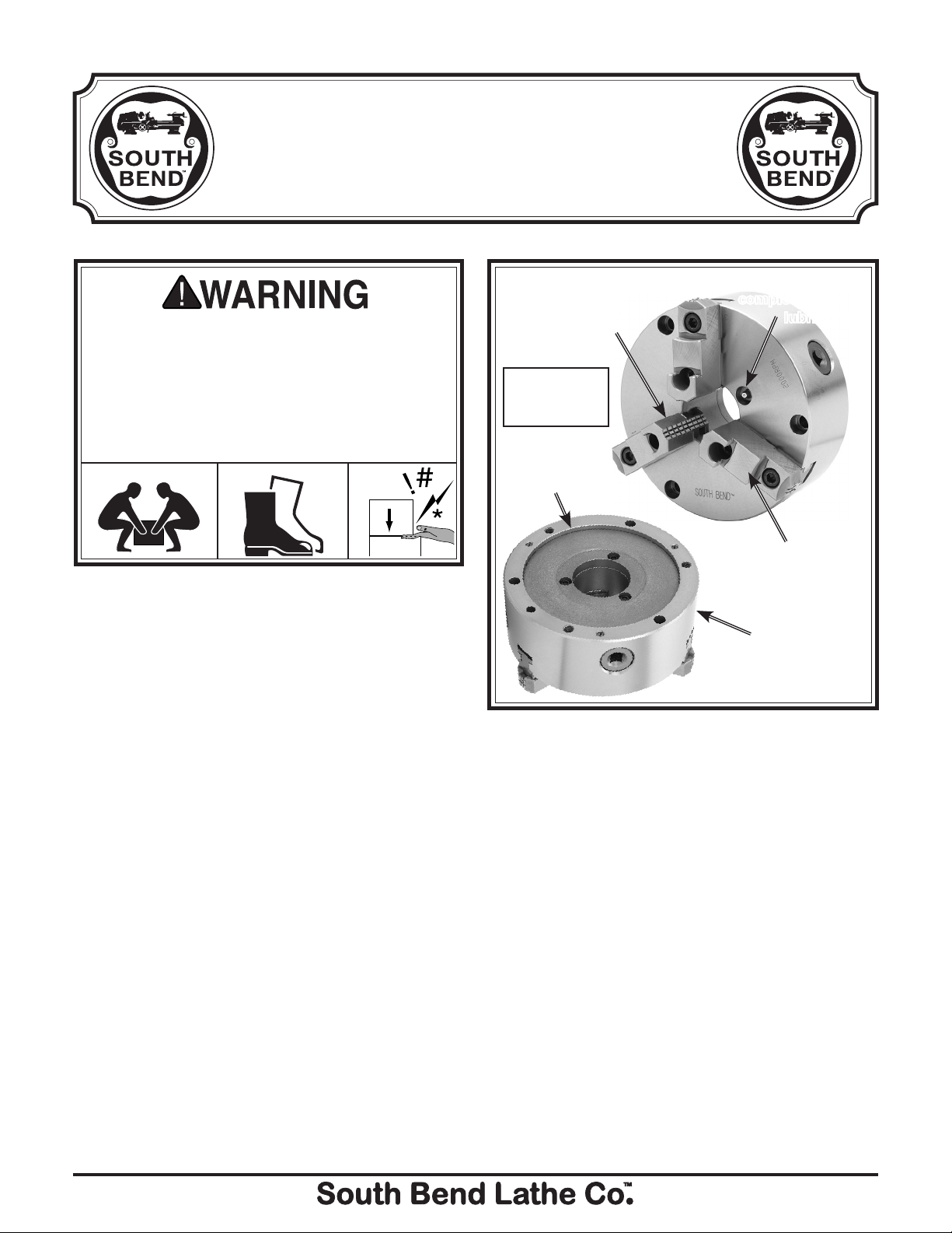
Hardened steel jaws
for durability and
extreme clamping
force and grip.
Designed for
up to
2000 RPM.
Universal
plain-back
mounting.
Figure 1. Features.
Grease fitting for
complete internal
lubrication.
Two-piece
jaws for speedy
internal/external
clamping changes.
Manufactured
with high-tech
German CNC
machinery.
Installation
1. UNPLUG THE MACHINE FROM POWER!
2. Mount the back plate on the spindle.
3. Accurately measure the inside of the back
relief bore on the chuck. This dimension is
critical and should be ± 0.001''.
4. Face the back plate to true it. Make passes
across the face until its entire surface has
been cut.
If you need help with your new item, contact
us at: (360) 734-1540 • FAX: (360) 676-1075
1
5. Turn a shoulder into the face
0.001" to 0.002'' larger than the back relief
bore diameter. Remember that this is a press
fit. Chamfer the corner a small amount to
prevent any burrs when installing.
⁄8'' deep and
-1-
Page 2

6. Set the chuck on the back plate, aligning the
shoulder with the relief bore. Use a transfer
punch to mark the back plate. If a transfer
punch is not available, a drill bit of the same
size as the mounting holes in the chuck can
be used. Lightly tap on the bit, rotate it 90°
and tap it again.
7. Remove the chuck from the back plate and
center punch the marks. Drill and tap the
holes for M10-1.5 threads.
8. Remove the back plate from the lathe, and
place it in to a freezer for 30 minutes, and
place the chuck in an oven at 100° F. for the
same amount of time.
9. Put on insulated leather gloves and place
the chuck on the back plate. Line up the
mounting holes and thread in the cap screws
supplied.
10. Snug the first M10-1.5 cap screw, then
alternate the cap screws across the chuck
until you reach a final torque of 53.5 ft/lbs.
Alternating the tightening process insures
the chuck will be pressed on straight. This
step should be repeated until the back plate
fits snugly against the chuck. If the chuck
fits loosely on the back plate, or is crooked on
the shoulder, it will be necessary to recut the
back plate face and shoulder again. If you
are also installing the chuck by threading
the M10-1.5 hex bolts into the chuck from
the back side of the mounting plate, repeat
Step 9 on these bolts, but torque them to
53.5 ft/lbs.
Operation and Safety
• Chuck Key Safety: A chuck key left in the
chuck can become a dangerous projectile
when the spindle is started. Always remove
the chuck key after using it. Develop a habit
of not taking your hand off of a chuck key
unless it is away from the machine.
Disconnect Power: Disconnect the lathe
•
from power before installing and removing
the chuck or doing any maintenance or
adjustments. Accidental lathe startup can
cause severe injury or death.
Secure Clamping: A thrown workpiece may
•
cause severe injury or even death. When
swapping the chuck jaw positions, use a
torque wrench to re-torque the M10-1.5 jaw
mounting cap screws to 53.5 ft/lbs. When
clamping a workpiece, maximum gripping
force is attained at full jaw and scroll gear
engagement. If jaw and scroll gear are partially engaged, clamping force is reduced.
Speed Rates: Operating the lathe where
•
maximum chuck speed is exceeded, or at too
high of a speed for an unbalanced workpiece,
can cause the workpiece to be thrown from
the chuck. Always use the appropriate feed
and speed rates. A thrown workpiece may
cause severe injury or even death.
Large Chucks: Large chucks are very
•
heavy and difficult to grasp, which can lead
to crushed fingers or hands if mishandled.
Get assistance when installing or removing
large chucks to reduce this risk. Protect your
hands and the precision ground ways by
using a chuck cradle or piece of plywood over
the ways of the lathe when servicing chucks.
Safe Clearances: Often chuck jaws will
•
protrude past the diameter of the chuck and
can contact a coolant nozzle, tooling, tool
post, or saddle. Before starting the spindle,
make sure the workpiece and the chuck
jaws have adequate clearance by rotating it
through its entire range of motion by hand.
Stopping Lathe By Hand: Stopping
•
the spindle by putting your hand on the
workpiece or chuck creates an extreme risk
of entanglement, impact, crushing, friction,
or cutting hazards. Never attempt to slow
or stop the lathe chuck by using your hand.
Allow the spindle to come to a stop on its
own or use the brake (if equipped).
Long Stock Safety: Long stock can whip
•
violently if not properly supported, causing
serious impact injury and damage to the
lathe. Reduce this risk by supporting any
stock that extends from the chuck/headstock
more than three times its own diameter.
Always turn long stock at slow speeds.
-2-
Page 3
Care & Maintenance
!
Always disconnect
machine from power before
performing maintenance or
serious personal injury may
result.
3
6
5
4
7
For optimum performance from your chuck,
follow the maintenance schedule below, and
never hammer on the chuck, jaws, or a workpiece
clamped in the chuck. Never subject the chuck to
abrasives, flame, or water.
Daily:
• Check/correctloosemountingbolts.
• Keep the chuck clean and oiled.
• Use a vacuum, rag, or brush to clean the
chuck after use. Never use air pressure to
clean chips away from a chuck.
• Avoidleavingthechuckclampedona
workpiece, unload the chuck jaws daily.
• Makesurethechuckkeyisremovedfrom
the chuck when not using the key.
If the chuck ever becomes stiff to operate, it may
have been contaminated with metal chips or
abrasives from neglect or poor service practices.
The chuck must be dissembled, cleaned, and re-
lubricated.
To disassemble the chuck for a full cleaning
and lubrication service:
1. UNPLUG THE MACHINE FROM POWER!
2. Mark the chuck and the mounting plate
where they mate to ensure that when
reassembled both halves line up. Next,
unbolt the chuck and separate both halves.
3. Insert and rotate the chuck key
counterclockwise until the scroll-gear has
released all three jaws.
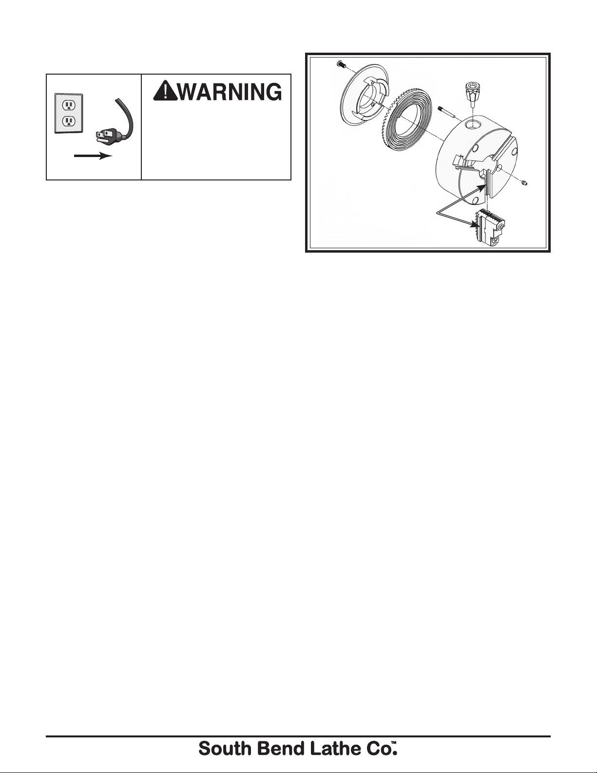
4. Using a basic set of metric hex wrenches
and a #1 standard screwdriver, start at #1
and disassemble the chuck in the sequence
shown in Figure 2.
Note: Each jaw is marked
1, 2, or 3 to correspond
to its marked slot in the
chuck.
Figure 2. Chuck sequence of disassembly.
5. Using mineral spirits, clean and dry all
components. Inspect all bores, teeth, pins,
and mating surfaces for wear, burrs, galling,
rust, or cracks.
6. Without changing the dimension of any part,
use a wire brush, emery cloth, or dressing
stones, to remove all rust, burrs, and any
high spots caused by galling.
7. Coat all parts with any automotive NLGI #2
grease, and carefully reassemble the chuck
in the reverse order shown in Figure 2.
8. Rotate the chuck key clockwise until you
see the tip of the scroll-gear lead thread just
begin to enter jaw guide #1.
9. Insert jaw #1 into jaw guide #1, and hold the
jaw against the scroll-gear.
10. Rotate the chuck key clockwise one turn to
engage the tip of the scroll-gear lead thread
into the jaw. Pull the jaw; it should be locked
into the jaw guide.
11. Install the other jaws in the same manner,
and install a new grease fitting.
12. Line up the timing mark on the chuck and
the mounting plate, and fasten both halves
by tightening and torquing the fasteners as
outlined in Step 9 in Chuck Installation.
1
2
-3-
Page 4
Troubleshooting
1
13
10
12
11
6
8
9
7
4
3
5
2
15
14
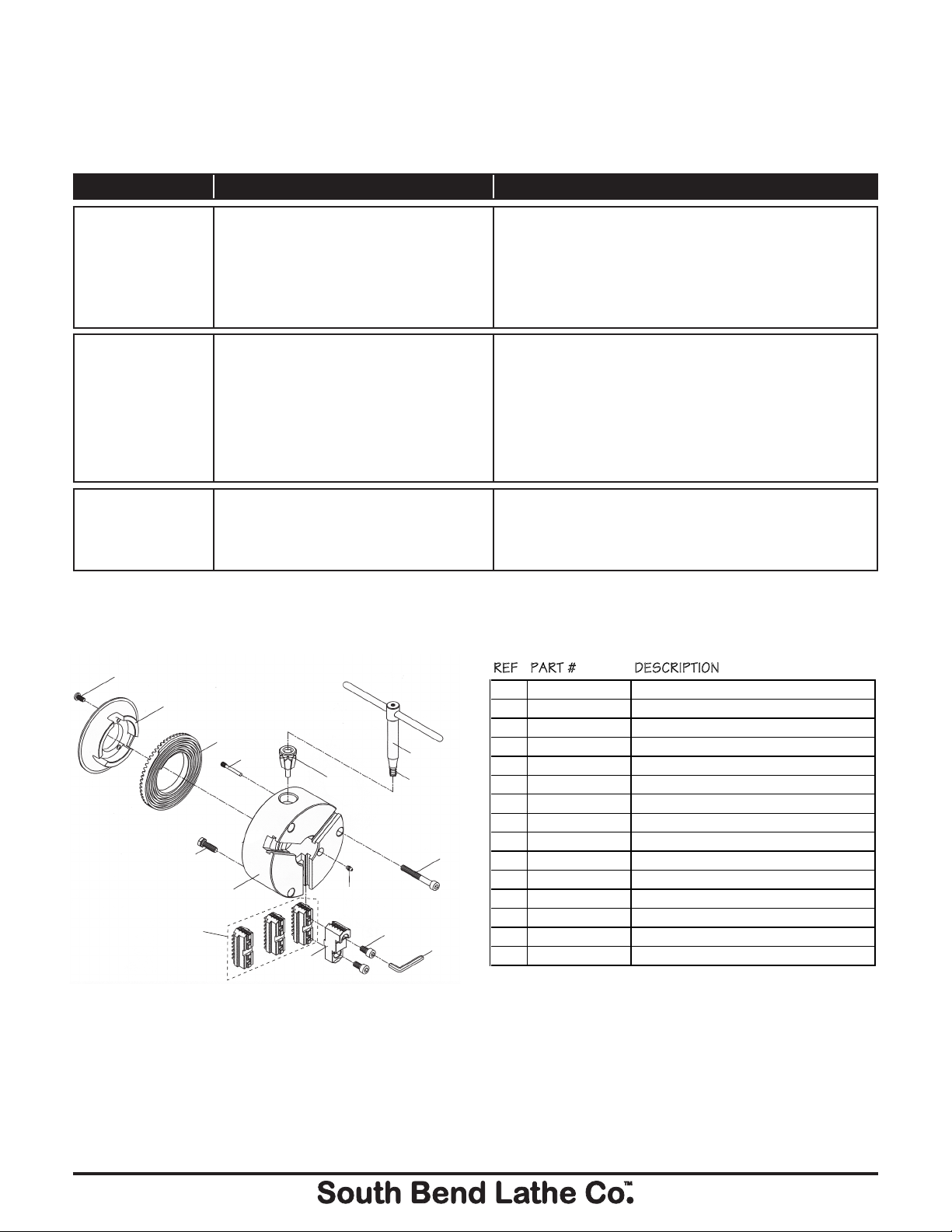
REF PART # DESCRIPTION
1 PSB1308001 GREASE FITTING
2 PSB1308002 TOP JAW
3 PCAP115M BUTTON HD CAP SCR M6-1 X 16
4 PSB1308004 BACK COVER
5 PSB1308005 LOCK PIN
6 PSB1308006 PINION
7 PSB1308007 SCROLL GEAR
8 PSB1308008 CHUCK KEY W/SPRING
9 PSB1308009 COMPRESSION SPRING
10 PSB1308010 CAP SCREW M10-1.5 X 80 BLK C12.9
11 PSB1308011 CAP SCREW M10-1.5 X 20 BLK C12.9
12 PAW08M HEX WRENCH 8MM
13 PSB1308013 BOTTOM JAW SET OF 3
14 PSB1308014 CHUCK BODY
15 PSB1308015 HEX BOLT M10-1.5 X 35 BLK C12.9
If you need replacement parts, or if you are unsure how to do any of the solutions given here, feel free
to call us at (360) 734-1540.
Symptom Possible Cause Possible Solution
The chuck has
hard spots or binds
completely.
The workpiece slips
in the jaws.
Clamping accuracy
is poor.
Jaw is in wrong position.
1.
Lack of lubrication, rust, burr, or
2.
metal shavings inside of chuck.
Broken tooth on the pinion or the
3.
scroll gear.
Incorrect jaw or workpiece clamping
1.
position.
Insufficient pinion and scroll gear
2.
torque.
Cutting overload.
3.
Chuck is binding before full
4.
clamping is achieved.
Workpiece improperly clamped or
1.
jaw is loose or incorrectly seated.
Chuck loose, mounting is off center,
2.
or it is improperly seated.
Reinstall jaws in correct order and position on scroll
1.
gear.
Disassemble, de-burr, clean, and lubricate chuck.
2.
Disassemble and rebuild chuck.
3.
Reposition jaws and workpiece for maximum scroll
1.
gear and jaw engagement is achieved.
Tighten chuck key to 72 ft/lbs.
2.
Reduce cutting depth or feed rate.
3.
Disassemble and service/rebuild chuck.
4.
Remove jaws, clean, de-burr, and reinstall with jaw
1.
mounting caps crews torqued to 53.5 ft/lbs.
Remove chuck, clean and de-burr mounting, and
2.
reinstall, or machine a new mounting plate.
Parts Diagram Parts List
Please Note: We included this breakdown for service purposes only. Since many of the parts shown are machined to each
individual chuck, they are not available as replacement items.
Copyright © January, 2010 By South Bend Lathe Co.
WARNING: No portion of this manual may be reproduced in any shape or form
without the written approval of South Bend Lathe Co.
-4-
#CR12484 Printed in Taiwan.
www.southbendlathe.com
 Loading...