

Page 1
MODEL SB1263
TAPER ATTACHMENT
Instruction Sheet
PHONE: (360) 734-1540 • www.southbendlathe.com
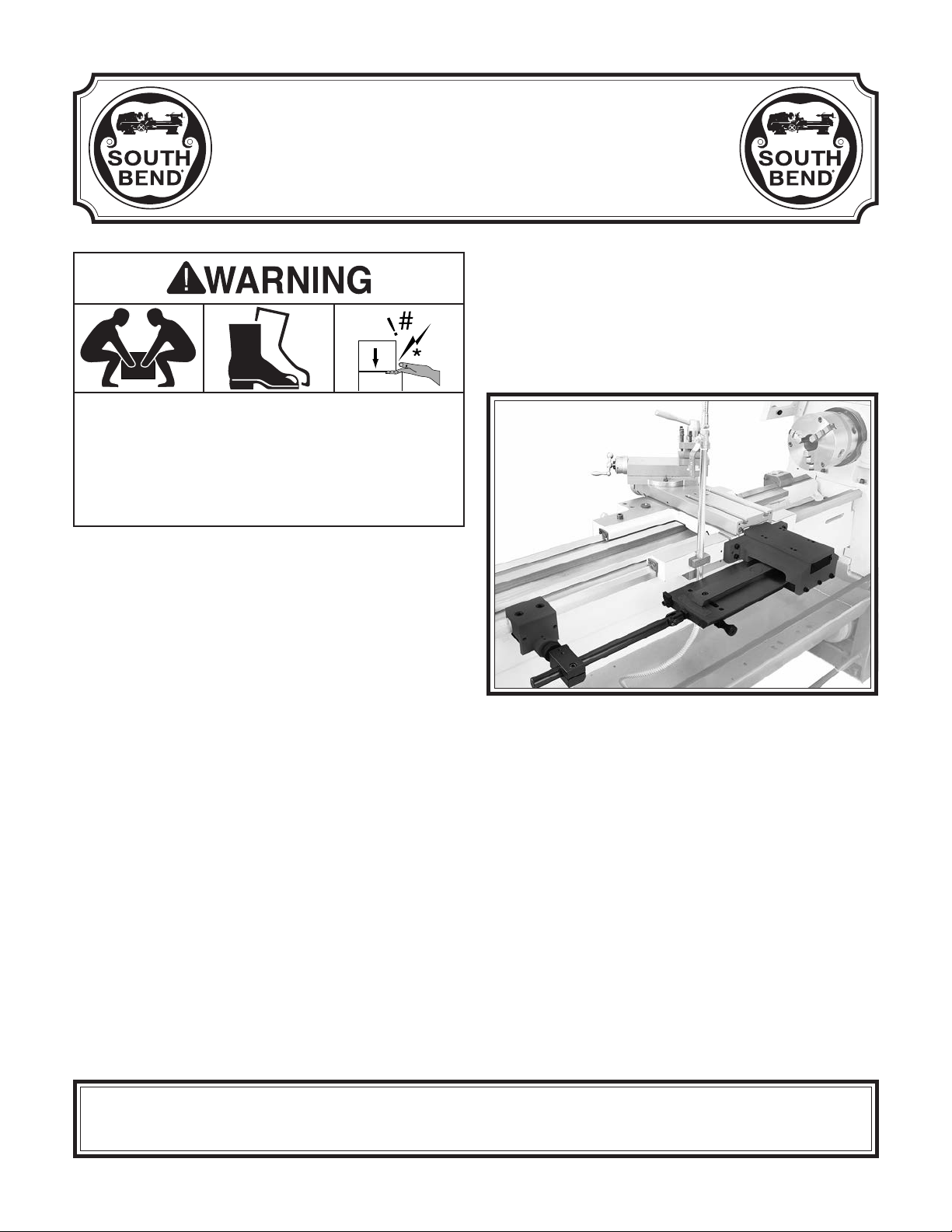
This taper attachment is heavy! Get
assistance when installing it on the lathe.
Wear heavy-duty leather boots with toe
protection, and keep hands and fingers away
from all pinch points. Ignoring this warning
can lead to severe crushing injuries!
Introduction
This taper attachment mounts quickly to the
back bedway of your lathe, as shown in Figure 1.
Accurate tapers can be cut without repositioning
the attachment or having to offset the tailstock.
Specifications
Designed for Lathe Models ... SB1039, SB1049–52
Taper Per Inch Range ........................ ±0.00°–0.18”
Maximum Taper Length ......................................9"
Minor Inch Scale Divisions .............................0.01”
Major Inch Scale Divisions .............................0.02”
Taper Angle Range ....................................±0°–10°
Minor Angle Scale Divisions...............................
Major Angle Scale Divisions ................................1°
Construction .................................. Cast Iron, Steel
Net Weight ................................................... 49 lbs.
Shipping Weight ........................................... 60 lbs.
Factory ........................................................ Taiwan
1
⁄2°
Figure 1. Taper attachment installed on rear of lathe.
Note: Splash guard removed for clarity.
The Model SB1263 features an inches scale and
a degree scale. An angle adjusting knob with fine
threads achieves precise control when setting
tapers.
Another feature is the ability to use the taper
attachment without disengaging the cross slide
nut. This design allows the taper attachment to
be functional at any time by simply tightening
the two deadman clamp cap screws, which lock
the deadman clamp to the rear lathe way.
Copyright © January, 2012 by South Bend Lathe Co. Revised January, 2014 (ST)
WARNING: No portion of this manual may be reproduced without written approval.
For Product Manufactured Since 9/11 #TS14639 Printed in Taiwan
Page 2
Model SB1263
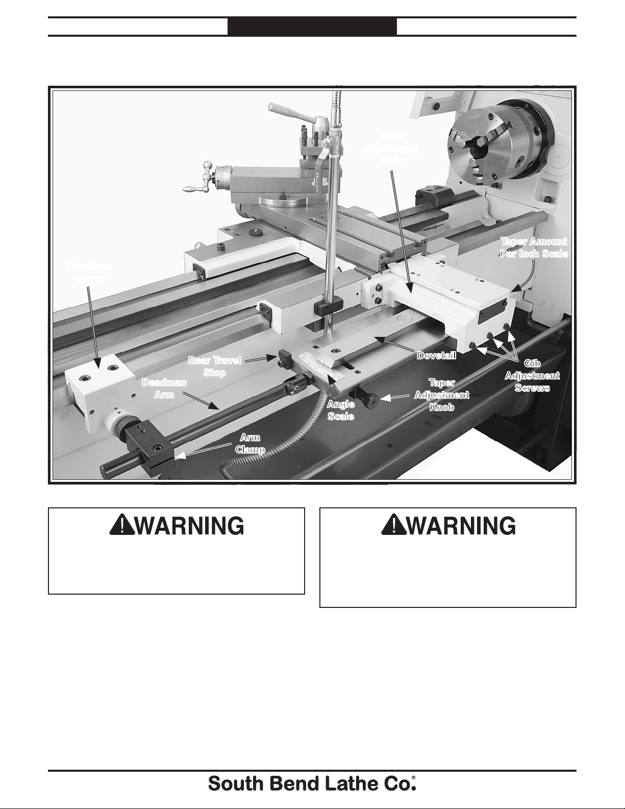
Identification
Deadman
Clamp
INSTRUCTIONS
Taper
Attachment
Body
Mfg. Since 9/11
Taper Amount
Per Inch Scale
Rear Travel
Stop
Deadman
Arm
Arm
Clamp
Figure 2. Model SB1263 identification.
Serious personal injury could occur if you
connect the lathe to power before completing
the setup process. DO NOT connect power
until instructed to do so later in this manual.
Angle
Scale
Dovetail
Taper
Adjustment
Knob
Gib
Adjustment
Screws
Untrained users have an increased risk
of seriously injuring themselves with this
machine. Do not operate this taper attachment
until you have understood this entire manual
and received proper training.
-2-
Page 3
This item was carefully packaged to prevent
damage during transport. If you discover any
damage, please immediately call Customer
Service at
need to file a freight claim, so save the containers
and all packing materials for possible inspection
by the carrier or its agent.
Mfg. Since 9/11 Model SB1263
INSTRUCTIONS
Unpacking
(360) 734-1540 for advice. You may
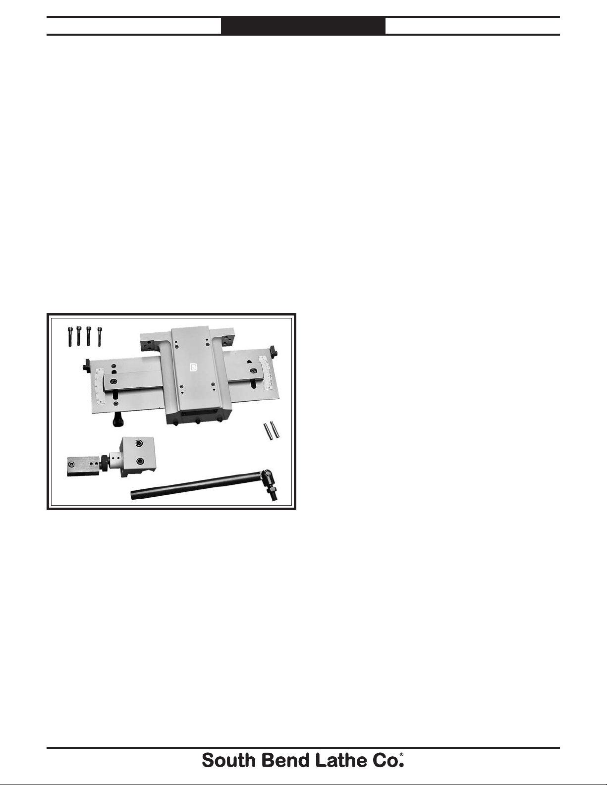
Inventory
Inventory (Figure 3) Qty
A. Cap Screws M8-1.25 x 45mm ........................4
B. Taper Attachment Assembly ......................... 1
C. Taper Pins 8.7 x 7.7 x 47mm ......................... 2
D. Deadman Clamp Assembly ...........................1
E. Deadman Arm Assembly ............................... 1
A
B
Required for Setup
The items listed below are required to
successfully set up and prepare this taper
attachment for operation. The installation
is intended to be permanent and will take
approximately one hour.
For Assembly
• Another person
• Cotton shop rags
• Mineral spirits
• Safety glasses
• Oil can with any general machine oil
• White lithium grease
• Wrench 17mm
• Hex wrenches 3, 4, 5, 6, and 8mm
• Phillips screwdriver #2
• Precision ruler
• Drill bit
• Tapered drill bit 8mm
• Spiral pin reamer #6
— Small end diameter: 0.2773"
— Large end diameter: 0.3540"
• Small metal hammer
• Dial indicator w/magnetic base
19
⁄64"
D
Figure 3. Model SB1263 inventory.
C
E
-3-
Page 4
Model SB1263
INSTRUCTIONS
Mfg. Since 9/11
Cleanup
The unpainted surfaces of your taper attachment
are coated with a heavy-duty rust preventative
that prevents corrosion during shipment and
storage. This rust preventative works extremely
well, but it will take a little time to remove.
Be patient and do a thorough job cleaning your
taper attachment. The time you spend doing this
now will give you a better appreciation for the
proper care of the unpainted surfaces.
There are many ways to remove this rust
preventative, but the following steps work well
in a wide variety of situations. Always follow the
manufacturer’s instructions with any cleaning
product you use and make sure you work in a
well-ventilated area to minimize exposure to
toxic fumes.
Note: The inner surfaces of the taper attachment
body were lubricated at the factory and do not
need to be cleaned at this time.
Before cleaning, gather the following:
• Disposable rags
• Cleaner/degreaser (WD•40 works well)
• Safety glasses & disposable gloves
• Plastic paint scraper (optional)
Basic steps for removing rust preventative:
1. Put on safety glasses and gloves.
Installation
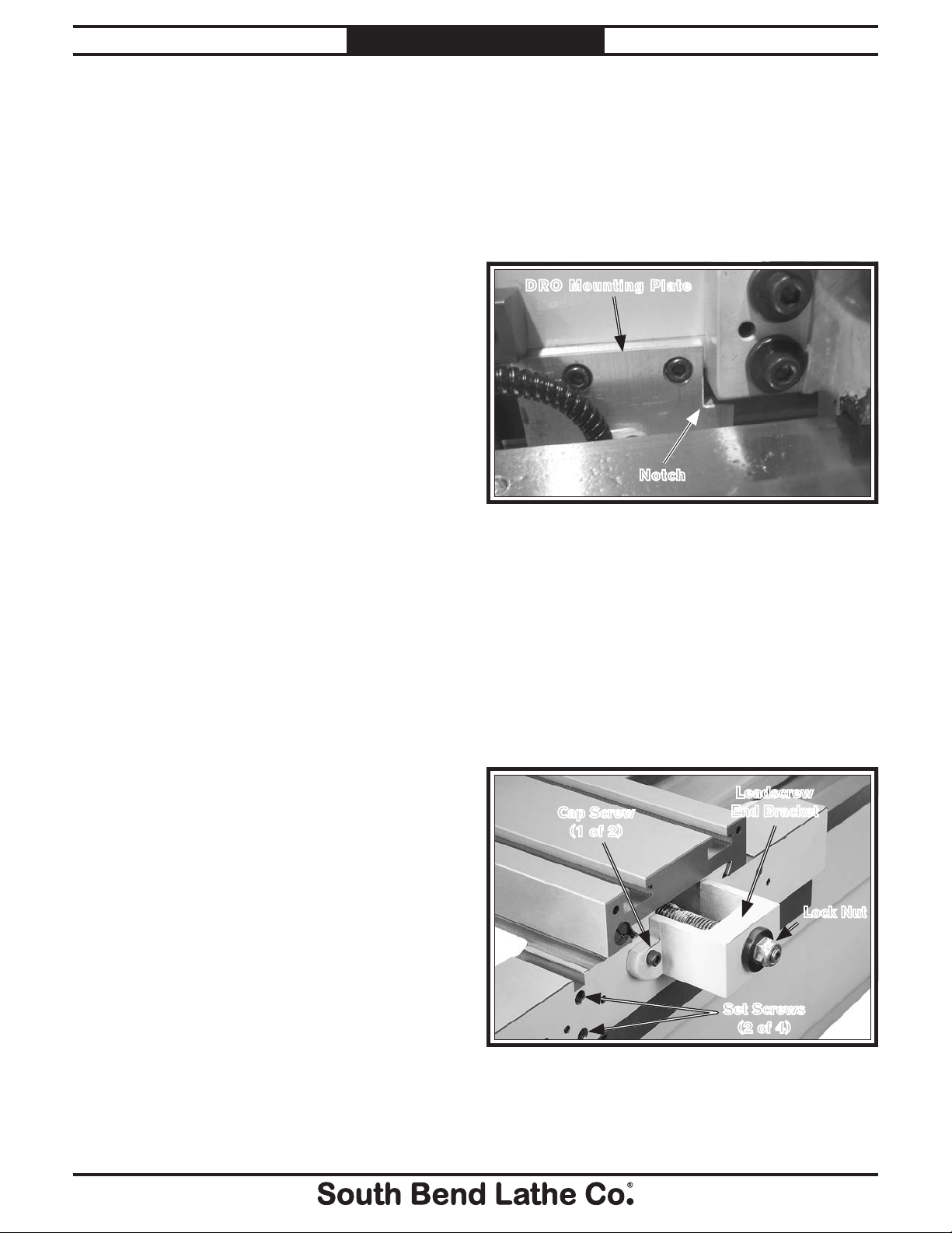
This procedure explains installation of the taper
attachment on a lathe without a DRO installed.
If the lathe has a Fagor DRO, the aluminum
mounting plate (or the taper attachment
housing) will need to have a small notch cut into
it (see Figure 4) to ensure proper fit.
DRO Mounting Plate
Notch
Figure 4. Notch in DRO mounting plate, allowing taper
attachment housing to fit.
To install the taper attachment:
1. DISCONNECT LATHE FROM POWER!
2. With the help of another person, remove the
splash guard on the rear of the lathe.
3. Move the cross slide all the way toward the
front of the lathe to fully expose the leadscrew end bracket (see Figure 5).
2. Coat the rust preventative with a liberal
amount of cleaner/degreaser, then let it soak
for 5–10 minutes.
3. Wipe off the surfaces. If your cleaner/
degreaser is effective, the rust preventative
will wipe off easily. If you have a plastic
scraper, scrape off as much as you can first,
then wipe off the rest with a rag.
4. Repeat Steps 2–3 as necessary until clean,
then coat all unpainted surfaces with a
quality way oil to prevent rust.
-4-
Leadscrew
Cap Screw
(1 of 2)
Figure 5. Leadscrew end bracket and fasteners.
4. Remove the two cap screws from the end
bracket (see Figure 5).
End Bracket
Lock Nut
Set Screws
(2 of 4)
Page 5
!
Mfg. Since 9/11 Model SB1263
INSTRUCTIONS
5. Remove the four set screws (see Figure 5)
from the saddle. These holes will be used to
mount the taper attachment to the saddle in
a later step.
6. Remove the lock nut (see Figure 5) from the
end of the leadscrew.
7. Keep the bearing parts together in the same
orientation as they were installed as you
remove them and the end bracket from the
leadscrew (see Figure 6).
Important: If a race is stuck to the surface of the
end bracket, use penetrating oil or mineral
spirits to separate the parts. Do not pry a
race loose, as this can damage it.
Inner Bearing Assembly
Outer Bearing
Assembly
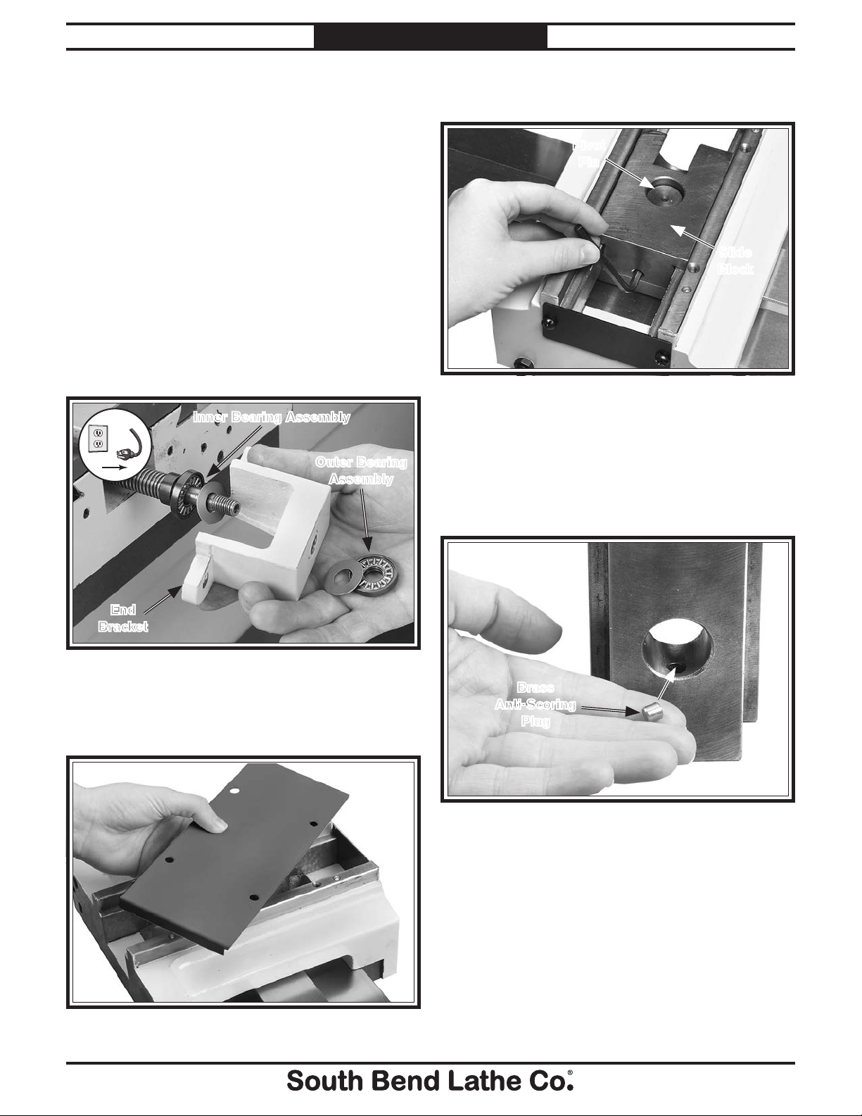
9. Loosen the set screw that secures the slide
block to the pivot pin, as shown in Figure 8.
Pivot
Pin
Slide
Block
Figure 8. Slide block removal.
10. Lift the slide block off the pivot pin. Make
sure not to dislodge the brass anti-scoring
plug shown in Figure 9.
Note: If the anti-scoring plug falls out of the slide
block, use a dab of grease to hold it in place.
End
Bracket
Figure 6. Leadscrew end bracket removed.
8. Remove the four flat head screws that secure
the top cover, then remove the cover (see
Figure 7).
Brass
Anti-Scoring
Plug
Figure 9. Slide block brass anti-scoring plug.
Figure 7. Attachment body top cover removed.
-5-
Page 6

!
!
Model SB1263
INSTRUCTIONS
Mfg. Since 9/11
11. Unthread the two cap screws that secure the
end bracket (see Figure 10) and remove it
from the slide block.
End
Bracket
Slide Block
Figure 10. End bracket removed from slide block.
12. Carefully clean the bearing parts that you
removed in Step 7 with mineral spirits.
When they are dry, repack them with white
lithium grease and re-assemble them.
13. Install the inner bearing assembly, the end
bracket, and the outer bearing assembly
onto the leadscrew in the order shown in
Figure 11, then secure them with the
leadscrew lock nut removed in Step 6.
Note: Tighten the lock nut until the bearings are
slightly pre-loaded and the end bracket has
zero end play—do not over-tighten it.
14. Secure the slide block onto the end bracket
with the two cap screws removed in Step 11,
as shown in Figure 12.
Pivot
Bore
Slide Block
Way (1 of 2)
Figure 12. Slide block installation.
15. Apply a thin coat of white lithium grease to
the inside of the pivot bore and both slide
block ways (see Figure 12).
Note: Make sure the brass plug remains inside
the slide block.
16. With the help of another person, raise the
taper attachment body underneath the
slide block so the pivot pin slides into the
pivot bore (see Figure 13), then secure the
assembly to the saddle with the four M8-1.25
x 45 cap screws.
Cap Screw
(1 of 4)
Pivot Pin
& Bore
Figure 11. End bracket and outer bearing assembly
installation.
-6-
Taper Attachment
Body
Figure 13. Taper attachment body installed.
Page 7

!
Mfg. Since 9/11 Model SB1263
INSTRUCTIONS
1 7. Snug the slide block set screw until the brass
plug is slightly pre-loaded against the pivot
pin (see Figure 14).
Figure 14. Slide block set screw adjustment.
18. Replace the attachment body top cover.
19. Loosen the two cap screws on top of the
deadman clamp (see Figure 15), then slide
the clamp onto the rear bedway from the
tailstock end.
20. Thread the arm clevis into the taper
attachment, then position the deadman
clamp so the end of the arm slides into the
arm clamp, as shown in Figure 16.
Note: Do not tighten the arm clamp cap screw or
the arm clevis hex nut at this time.
Deadman Clamp
Cap Screws
Arm
Clevis
Arm Clamp
Figure 16. Deadman clamp and arm.
21. Position the deadman clamp towards the end
of the arm, then tighten the deadman clamp
cap screws to secure the assembly to the
bedway.
Cap Screws
Arm
Clamp
22. Loosen the dovetail cap screws at each end of
the taper attachment body (see Figure 17).
Dovetail Cap
Screw (1 of 2)
Clamping
Plate
Figure 15. Deadman clamp.
Rear
Angle Scale
Adjustment Knob
Figure 17. Taper adjustment knob and controls.
23. Turn the taper adjustment knob to bring the
dovetail to zero on both scales.
-7-
Page 8

Model SB1263
INSTRUCTIONS
Mfg. Since 9/11
24. Re-tighten both dovetail cap screws to secure
the zero setting.
25. Move the carriage toward the tailstock until
the taper attachment body is against the
rear travel stop (see Figure 18).
Note: If necessary, reposition the deadman clamp
on the arm so that it is at least 1" away from
the saddle (see Figure 18) and re-tighten
the clamp cap screws. This “saddle safety
gap” will prevent the saddle crashing into
the deadman clamp during taper operations.
Complete Travel Without
Deadman Clamp Contact
1" Saddle
Safety Gap
2 7. Inspect the assembly to determine if the
deadman arm is parallel horizontally and
vertically with the bedway.
— If the arm is parallel horizontally and
vertically with the bedway, proceed to
Step 26.
— If the arm is not horizontally parallel with
the bedway:
a. Loosen the four adjustment cam set
screws shown in Figure 19.
Adjustment Cam
Set Screws
Rear Travel Stop
Figure 18. Saddle gap.
You will need to perform Step 25 each time
you secure the deadman clamp to the bedway
to cut a taper to prevent the carriage crashing
into the deadman clamp.
26. Move the carriage toward the headstock
until the taper attachment is against the
front travel stop.
Note: In the following step, it may be necessary
to rotate the arm so the clevis allows the arm
to tilt in a particular direction.
Adjustment
Cam
Figure 19. Adjustment cam set screws.
b. Slide the adjustment cam and arm
clamp toward or away from the
deadman clamp until the arm is
horizontally parallel with the bedway.
c. Re-tighten the adjustment cam set
screws.
— If the arm is not vertically parallel with
the bedway:
a. Loosen the four adjustment cam set
screws shown in Figure 19.
b. Rotate the knurled adjustment cam
until the arm is vertically parallel with
the bedway.
-8-
c. Re-tighten the adjustment cam set
screws.
Page 9

!
Mfg. Since 9/11 Model SB1263
INSTRUCTIONS
28. Tighten the arm clamp cap screw (see
Figure 20) to secure the deadman clamp
assembly to the arm.
Clevis
Hex Nut
Arm Clamp
Cap Screw
Figure 20. Arm clamp cap screw and clevis hex nut.
29. Tighten the arm clevis hex nut to secure the
attachment to the arm.
32. Move the carriage and taper attachment to
the other end and note any change in the
reading.
— If the indicator reading is 0.025" or
less, the tilt of the attachment table
is considered acceptable. Proceed to
Step 35.
— If the indicator reading is greater than
0.025", proceed to Step 33 to correct the
attachment table tilt.
33. Loosen the four cap screws that secure the
attachment to the saddle, then rotate the
attachment assembly left or right to correct
the table tilt (see Figure 22).
Rotate
Body
30. Move the carriage toward the headstock
until the taper attachment is against the
front travel stop.
31. Mount the dial indicator magnetic base on
top of the saddle so that the indicator needle
is resting on the attachment table, as shown
in Figure 21, then zero the indicator.
Figure 22. Attachment table tilt adjustment.
34. Re-tighten the four cap screws to secure the
setting, then repeat Steps 32–33 to re-check
the table tilt.
Figure 21. Taper attachment alignment.
-9-
Page 10

Model SB1263
35. Drill two 19⁄64" holes into the saddle through
the pilot holes in the attachment casting (see
Figure 23).
INSTRUCTIONS
Mfg. Since 9/11
Operation
The taper attachment is engaged for operation
when the deadman clamp is tightened on the
bedway and disengaged for operation when the
deadman clamp is loosened.
Engaging Taper Attachment
1. DISCONNECT LATHE FROM POWER!
Pre-Drilled Pilot
Holes for Taper Pins
Figure 23. Taper pin pilot holes.
36. Ream the holes with the #6 spiral pin reamer
deep enough so that the taper pins will fit
flush to the attachment casting surface.
3 7. Carefully tap the taper pins into the holes
until they are flush with the casting surface
to secure the attachment tilt alignment with
the saddle.
Note: If you need to remove the taper pins, the
internal pin threads are M6-1.
38. Re-install the lathe splash guard.
2. Position the cutting tool at the proper
beginning position for the turning operation.
Note: Make sure that there will be at least 1"
clearance between the deadman clamp and
the saddle when the saddle is moved all the
way toward the tailstock (refer to Step 25 on
Page 8 for additional information).
3. Tighten the deadman clamp cap screws to
secure the clamp and taper attachment to
the bedway (see Figure 24).
Deadman Clamp
Cap Screws
-10-
Figure 24. Deadman clamp cap screws.
Page 11

Mfg. Since 9/11 Model SB1263
INSTRUCTIONS
4. Loosen both dovetail cap screws (see
Figure 25).
Dovetail Cap
Screw (1 of 2)
Figure 25. Dovetail cap screw
(1 of 2).
Note: Depending on the operation, use either the
rear scale (degrees of taper) or the front scale
(amount of taper per inch of workpiece) in
the next step (see Figure 26).
Disengaging Taper Attachment
1. DISCONNECT LATHE FROM POWER!
2. Loosen both deadman clamp cap screws (see
Figure 27)
Deadman Clamp
Cap Screws
Figure 27. Deadman clamp cap screws.
3. Loosen the dovetail way cap screws at each
end (see Figure 28).
Rear Scale Front Scale
Taper Angle
Taper Per/Inch
Workpiece
Length
Figure 26. Rear and front scales.
Dovetail Cap
Screw (1 of 2)
Figure 28. Dovetail way cap screw
(1 of 2).
4. Turn the taper adjustment knob until both
scales read zero.
5. Re-tighten both dovetail way cap screws.
5. Turn the taper adjustment knob to set the
required taper, then re-tighten both dovetail
cap screws.
-11-
Page 12

!
Model SB1263
INSTRUCTIONS
Mfg. Since 9/11
Maintenance
Always disconnect
lathe from power before
performing maintenance or
serious personal injury may
result.
Maintenance Schedule
For optimum performance from your taper
attachment, follow the maintenance schedule
below and refer to any specific instructions given
in this section.
Daily
• Check/correct loose mounting fasteners.
• Clean debris and grime from all attachment
surfaces.
• Clean/protect attachment table and dovetail
ways.
• Correct any other unsafe condition.
Monthly
• Disassemble, clean, and lubricate slide block,
pivot pin, and internal ways.
Cleaning & Protecting
Typically, the easiest way to clean debris and
grime from the attachment is to use a wet/dry
shop vacuum that is dedicated for this purpose.
The small chips left over after vacuuming can be
wiped up with a slightly oiled rag. Avoid using
compressed air to blow off chips, as it may drive
them deeper into moving surfaces and could
cause sharp chips to fly into your face or hands.
To keep the unpainted surfaces of the
attachment table and dovetail ways rust-free and
in top condition, apply a thin coat of a quality
way oil after cleaning them.
Lubricating Slide Block, Pivot Pin,
& Internal Ways
1. DISCONNECT LATHE FROM POWER!
2. Referring to the assembly instructions,
remove the attachment body top cover and
the slide block.
3. Clean the slide block, pivot pin, and the
internal ways with mineral spirits and shop
rags.
Important: Make sure the brass plug in the slide
block set screw hole remains in place during
cleaning and lubrication.
-12-
4. When dry, apply a thin coat of white lithium
grease to all surfaces of the slide block, pivot
pin, and internal ways of the attachment
body, then re-assemble the parts.
Page 13

Mfg. Since 9/11 Model SB1263
INSTRUCTIONS
Gib Adjustment
The goal of adjusting the gib screws is to remove
sloppiness or “play” from the ways without overadjusting them to the point where they become
stiff and difficult to move.
In general, loose gibs cause poor finishes and
inaccurate tapers; however, over-tightened gibs
cause premature wear and make it difficult to
move the carriage and cross slide.
Internal Gib
The internal gib is tapered and held in position
by a screw at each end (see Figure 29). To
adjust this gib, turn one screw
1
and the other screw
⁄4 turn counterclockwise,
so both screws move in the same direction and
the same amount. Test the feel of the setting by
moving the carriage, and adjust the gib screws as
necessary to make it tighter or looser.
1
⁄4 turn clockwise
External Gib
The external gib is wedge-shaped and is held
in position by three set screws (see Figure 30).
To adjust this gib, loosen the hex nuts and turn
the set screws in equal amounts. Test the feel of
the setting by moving the carriage, and adjust
the set screws as necessary to make it tighter or
looser. When satisfied with the movement, retighten the hex nuts to secure the setting.
Gib
Hex Nuts
& Set Screws
Gib Screw
(1 of 2)
Figure 29. Internal gib.
Figure 30. External gib.
Gib
-13 -
Page 14

Model SB1263
Parts Breakdown
INSTRUCTIONS
2
Mfg. Since 9/11
7
8
9
50
51
49
46
10
1
2
5
12
13
20
22
23
36
37
46
11
48
45
33
34
35
38
39
40
33
42
28
30
31
32
41
40
10
13
12
12
11
14
15
16
17
18
20
19
21
36
23
24
25
26
27
-14-
47
43
44
Page 15

Mfg. Since 9/11 Model SB1263
INSTRUCTIONS
Parts List
REF PART # DESCRIPTION REF PART # DESCRIPTION
1 PSB1263001 BUSHING BRASS 28 PSB1263028 PIVOT PIN
2 PSB1263002 CAP SCREW M6-1 X 20 30 PSB1263030 PIVOT SADDLE
5 PSB1263005 END CAP 31 PSB1263031 PIVOT SADDLE GIB
7 PSB1263007 FLAT HD SCR M6-1 X 8 32 PSB1263032 GIB SCREW
8 PSB1263008 TOP COVER 33 PSB1263033 CAP SCREW M8-1.25 X 25
9 PSB1263009 SLIDE BLOCK 34 PSB1263034 DOVETAIL WAY
10 PSB1263010 BRASS PLUG 35 PSB1263035 CAP SCREW M6-1 X 25
11 PSB1263011 SET SCREW M8-1.25 X 16 36 PSB1263036 CAP SCREW M8-1.25 X 20
12 PSB1263012 CAP SCREW M8-1.25 X 45 37 PSB1263037 COTTER PIN 4.5 X 30MM
13 PSB1263013 TAPER PIN 38 PSB1263038 CLEVIS
14 PSB1263014 BODY 39 PSB1263039 CLEVIS PIN
15 PSB1263015 PLATE 40 PSB1263040 NUT BLOCK M6-1 X 25
16 PSB1263016 PHLP HD SCR M6-1 X 10 41 PSB1263041 T-NUT M8-1.25
17 PSB1263017 SET SCREW M8-1.25 X 25 42 PSB1263042 NUT BLOCK
18 PSB1263018 HEX NUT M8-1.25 43 PSB1263043 LEADSCREW
19 PSB1263019 CAP SCREW M8-1.25 X 30 44 PSB1263044 KNOB
20 PSB1263020 STEEL FLUTED RIVET 2 X 5MM 45 PSB1263045 DEADMAN ARM
21 PSB1263021 INCH SCALE 0-14.5 46 PSB1263046 SET SCREW M6-1 X 12
22 PSB1263022 DEGREE SCALE 0-8.5 47 PSB1263047 ARM CLAMP
23 PSB1263023 STOP 48 PSB1263048 ECCENTRIC CAM
24 PSB1263024 TABLE 49 PSB1263049 CAP SCREW M10- 1.5 X 50
25 PSB1263025 T-NUT M8-1.25 50 PSB1263050 DEADMAN CLAMP
26 PSB1263026 TABLE GIB 51 PSB1263051 DEADMAN PLATE
27 PSB1263027 CAP SCREW M6-1 X 30
-15 -
Page 16

 Loading...